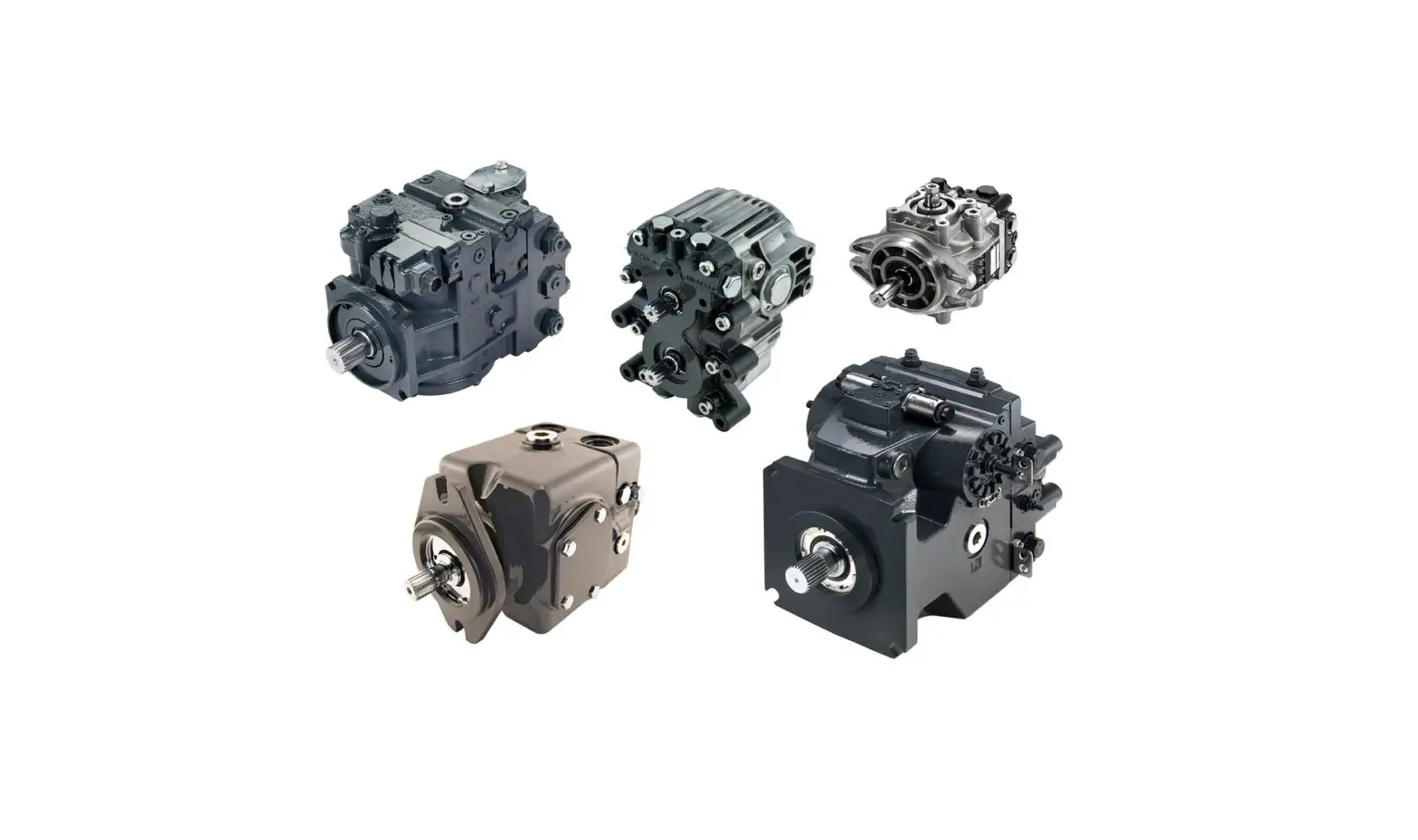
Danfoss PVQ 40 Low Noise Industrial Piston Pump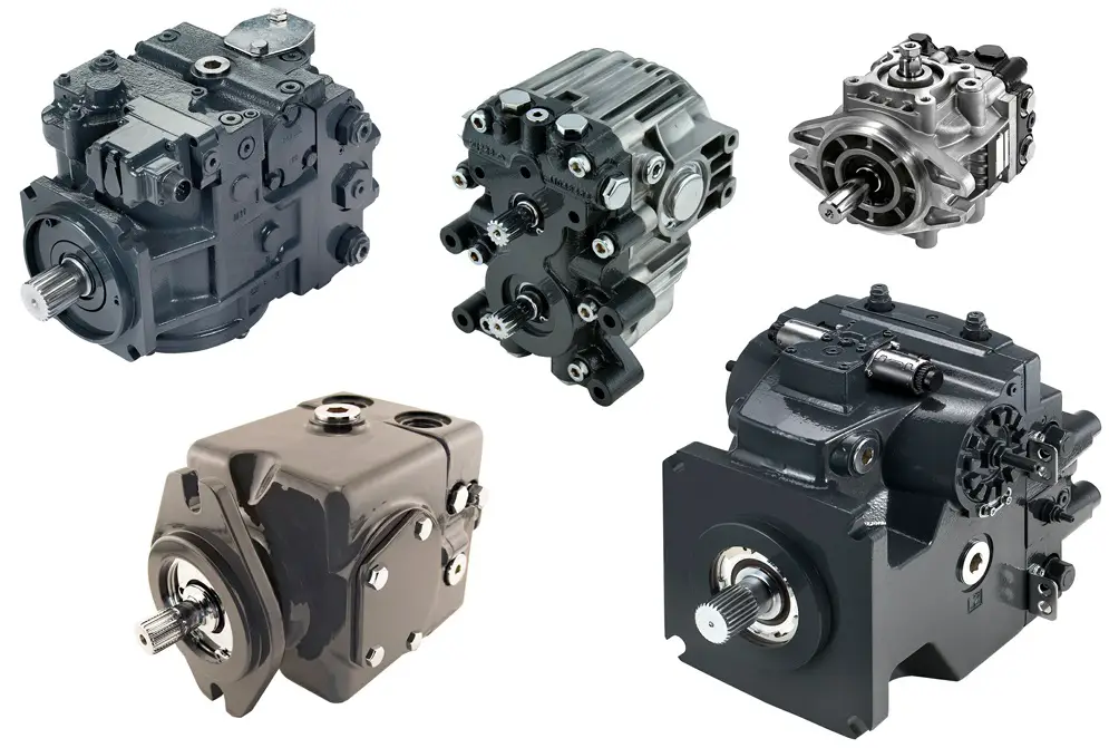
C**, CM** Compensator shown for
R. H. rotation. Rotate 180 for L. H. shaft rotation.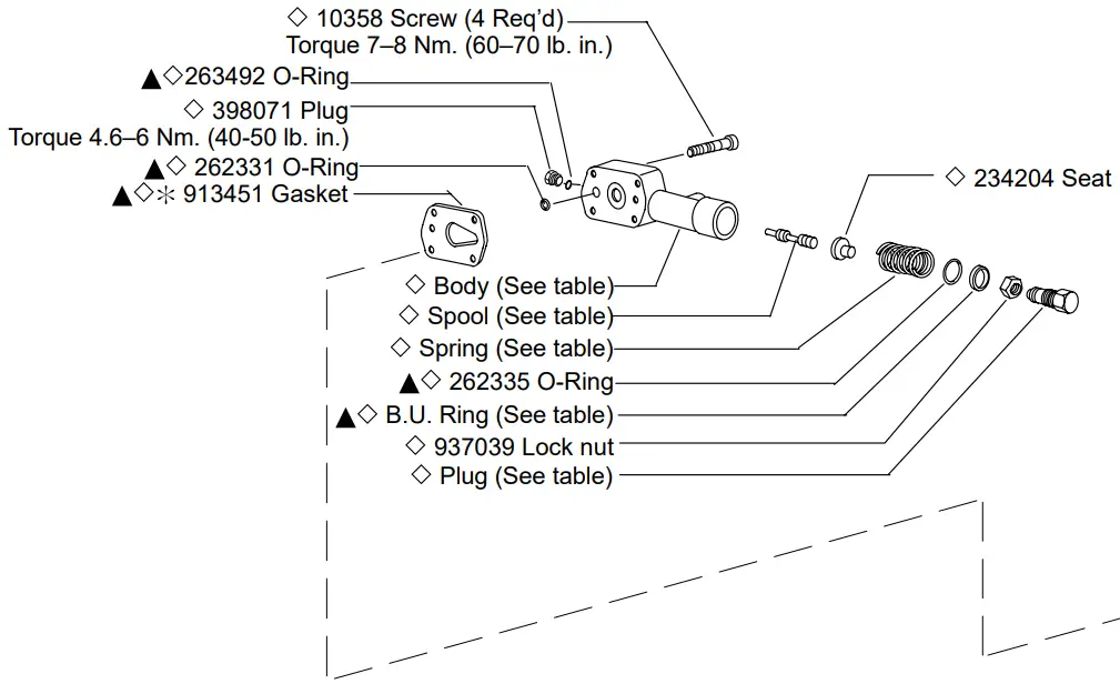
 Caution: Position gasket with small end of teardrop hole pointing in direction of compensator adjusting plug
| Type | Body | Spool | Spring | Plug | B.U. Ring |
| C | 934147 | 241717 | 239371 | 392175 | – |
| CG | 932966 | 296234 | 239371 | 944255 | 997049 |
| CM | 934147 | 241717 | 265693 | 392175 | – |
C**V(C)**B Compensator shown for R. H. rotation. Rotate 180 for L. H. shaft rotation.
See table for compensator kit part number.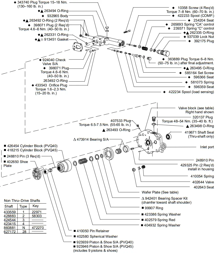
NOTE For satisfactory service life of these components in industrial applications, use full flow filtration to provide fluid which meets ISO cleanliness code 16/13 or cleaner. OFP, OFR, and OFRS series filters are recommended.
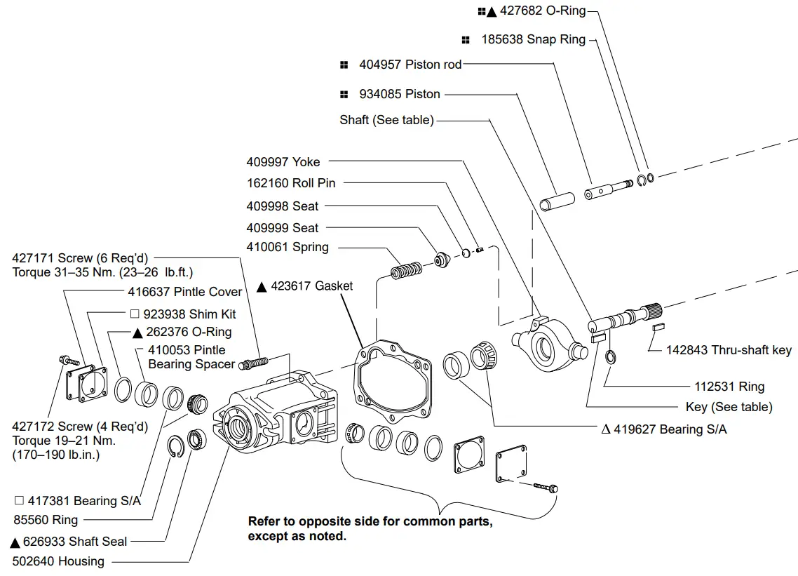
![]() Included in compensator kit
Included in compensator kit Included in standard seal kit 02-348242
![]() Included in shaft bearing kit 923988
Included in shaft bearing kit 923988![]() Included in yoke bearing kit 923987
Included in yoke bearing kit 923987![]() Rotating group kit 923948 (PVQ40)
Rotating group kit 923948 (PVQ40)![]() Rotating group kit 923947 (PVQ45)
Rotating group kit 923947 (PVQ45)![]() Included in piston rod kit 02-328397
Included in piston rod kit 02-328397
CAUTION Model PVQ45C compensator pressure adjustment shall not exceed 2750 psi.
NOTE See model code [10] for pressure range settings of individual compensator kits.
| Model | Comp. Kit | Comp. Spring | Load Sense Spring |
| PVQ40-C21-12 | 02-348260 | 239371 | |
| PVQ45-C19-12 | 02-348261 | ||
| PVQ**-CM7-12 | 02-348259 | 265693 | |
| PVQ**-CG-30 | 02-348262 | 239371 | |
| PVQ40-C21V11B-13 | 02-348193 | 581073 581072 581073 581072 581073 581072 581073 581072 | |
| PVQ40-C21VC24B-13 | 02-348250 | ||
| PVQ40-C21V11P-13 | 02-348247 | ||
| PVQ40-C21VC24P-13 | 02-348248 | ||
| PVQ45-C19V11B-13 | 02-348251 | ||
| PVQ45-C19VC24B-13 | 02-348249 | ||
| PVQ45-C19V11P-13 | 02-348252 | ||
| PVQ45-C19VC24P-13 | 02-348253 | ||
| PVQ**CD**** | (Refer to service parts information I-3255-S) | ||
| Model | Shaft end rotation | Wafer plate | Valve block | Thru-drive valve block | O-Ring |
| PVQ45*R*SS PVQ40*R*SS PVQ45*R*SE PVQ40*R*SE | Right hand (CW) | 629539 | 933002 | – | – |
| 933017 | |||||
| PVQ45*L*SS PVQ40*L*SS PVQ45*L*SE PVQ40*L*SE | Left hand (CCW) | 631476 | 933016 | ||
| 933007 | |||||
| PVQ4**RAFS PVQ4**RBSS | Right hand (CW) | 629539 | – | 937476 | 351776 |
| 627149 | 375422 | ||||
| PVQ4**LAFS PVQ4**LBSS | Left hand (CCW) | 631476 | 933000 | 351776 | |
| 933021 | 375422 |
Thru-Drive Shafts
| [5] Model | Shaft | [7] Input Type |
| PVQ**A9 | 883098 | 2 Str. Keyed SAE B–B |
| 586131 | 4 Splined SAE B–B | |
| PVQ**B26 | 677131 | 2 Str. Keyed SAE B–B |
| 423416 | 4 Splined SAE B–B |
Thru-Drive Couplings
| Thru-Drive Model Code | Coupling | O-Ring | Model Code Rear Pump | Rear Pump Shaft Type |
| PVQ**A9 | 864224 | 351776 | PVQ10 | 3 |
| V10 | 11 | |||
| V20 | 62 | |||
| PVQ**B26 | 627168 | 375422 | PVE12 | 28 |
| PVQ40/45 | 28 | |||
| PVQ20/32 | 28 | |||
| 475134 | 2520V | 166 |
Rear pump, couplings, O-rings, cap screws and washers must be ordered separately to mount rear pump.
| Thru-Drive Couplings | Type | Description |
| 864224 | A | “A” 9 tooth spline |
| 627168 | B | 26 tooth |
| 475134 | B | Step coupling 26 to 15 tooth “B–B” spline |
Model Code

- PVQ Series
P – Inline piston pump
V – Variable volume
Q – Quiet series - Displacement
(CC/Rev & Pressure ratings)
40 – 40 CC/Rev (2.50 CIR)
210 bar (3000 psi)
45 – 45 CC/Rev (2.75 CIR)
190 bar (2700 psi) - Mounting flange
B2 – SAE “B” 2-bolt
MB – ISO 3019/2 “B” 2-bolt (available with “N” drive shaft only) - Rotation (viewed from shaft end)
R – Right hand (CW) (standard)
L – Left hand (CCW) (optional) - Thru drive
(without coupling) Available with side ports only.
Blank – No thru drive
A9 – SAE “A” 2-bolt with 9T shaft
A11 – SAE “A” 2-bolt with 11T shaft
B13 – SAE “B” 2-bolt with 13T shaft
B26 – SAE “B” 2-bolt with 26T shaft
(Available only with #4 main input shaft) - Ports (type and location)
SE – Inch O-Ring boss rear port (standard)
SS – Inch O-Ring boss side port (optional)
FS – Flange side port (SAE “A” thru–drive only) - Shafts
(input)
1 – Straight keyed SAE “B”(not on thru drives)
2 – Straight keyed SAE “B–B”
3 – Splined SAE “B” modified 13T,
16/32 DP flat root side fit (not on thru drives)
4 – Splined SAE “B–B” modified 15T,
16/32 DP flat root side fit
N – ISO 3019/2 short straight keyed
(available with “MB” mounting only)
Not available on thru–drives.
28 – 26 tooth splined shaft (Vickers)
Used to mount PVQ40/45 on
PVQ40/45 thru–drive pump - Seals
S – Buna N (standard)
F – Fluorocarbon (optional) - Pump design number
10 – First design - Control type
C** – Pressure compensator, PVQ40: Std. model is C21, indicating factory setting of 210 bar (3000 psi). Range is 02–21 in tens of bar (350–3000 psi)
PVQ45: Std. model is C19, indicating factory setting of 190 bar (2750 psi).
Range is 02–19 in tens of bar (350–2750 psi)
CM** – Low pressure compensator, Std.
model is CM7, indicating factory setting of 70 bar(1000 psi). Range is 02–10 in tens of bar (350–1500 psi)
C**V**B – Pressure compensator C**, as above, with load sensing. Std. load sensing setting is 11 bar (160 psi). Range 10–17 bar (150–250 psi), with bleed down orifice.
Example: C21V11B indicates PVQ40 compensator with 210 bar pressure setting and 11 bar load sense differential.
C**V**P – Pressure compensator with load sensing as C**V**B above, but with bleed down orifice plugged.
C**VC**B – Pressure compensator with load sensing. Compensator same as C** above. Std. load sensing setting is 24 bar (350 psi). Range 17–31 bar (250–450 psi), with bleed down orifice
C**VC**P – Pressure compensator with load sensing.Same as C**VC**B above, but with bleed down orifice plugged.
CG – Pressure compensator modified forhydraulic remote control.
CD**** – Electric dual range compensator.
PVQ40: Std. model is CD2110, indicating dual pressure settings of 210 and 100 bar, adjustment ranges are 20–210 bar (high) and 20–100 bar (low). PVQ45: Std. model is CD1910, indicating settings of 190 and 100 bar, adjustment ranges are 20–190 bar (high) and 20–100 bar (low). - Control option
Blank – Without adjustable Max. displacement stop (standard)
D – Max. adjustable displacement stop
(optional) - Control design
12 – C**, C**D, CM** & CM**D
13 – C**V(C)**B & C**V(C)**P
21 – CD**** & UV
30 – CG
Products we offer
- Cartridge valves
- DCV directional control valves
- Electric converters
- Electric machines
- Electric motors
- Gear motors
- Gear pumps
- Hydraulic integrated circuits (HICs)
- Hydrostatic motors
- Hydrostatic pumps
- Orbital motors
- PLUS+1″ controllers
- PLUS+1° displays
- PLUS+1′ joysticks and pedals
- PLUS+1° operator interfaces
- PLUS+1″ sensors
- PLUS+1″ software
- PLUS+1′ software services, support and training
- Position controls and sensors
- PVG proportional valves
- Steering components and systems
- Telematics
Danfoss Power Solutions is a global manufacturer and supplier of high-quality hydraulic and electric components. We specialize in providing state-of-the-art technology and solutions that excel in the harsh operating conditions of the mobile off-highway market as well as the marine sector. Building on our extensive applications expertise, we work closely with you to ensure exceptional performance for a broad range of applications. We help you and other customers around the world speed up system development, reduce costs and bring vehicles and vessels to market faster.
Danfoss Power Solutions – your strongest partner in mobile hydraulics and mobile electrification.
Go to www.danfoss.com for further product information. We offer you expert worldwide support for ensuring the best possible solutions for outstanding performance. And with an extensive network of Global Service Partners, we also provide you with comprehensive global service for all of our components.
Customer Service
Hydro-Gear
www.hydro-gear.com Daikin-Sauer-Danfoss www.daikin-sauer-danfoss.com
Danfoss Power Solutions (US) Company
2800 East 13th Street Ames, IA 50010, USA Phone: +1 515 239 6000
Danfoss Power Solutions GmbH & Co. OHG
Krokamp 35 D-24539 Neumiinster, Germany Phone: +49 4321 871 0
Danfoss Power Solutions ApS
Nordborgvej 81 DK-6430 Nordborg, Denmark Phone: +45 7488 2222
Danfoss Power Solutions Trading (Shanghai) Co., Ltd.
Building #22, No. 1000 Jin Hai Rd Jin Qiao, Pudong New District Shanghai, China 201206 Phone: +86 21 2080 6201