welldana D34-180140 Heat pump FPH Super Silent
- Thank you for choosing Aqua inverter heat pump
- This manual provides you necessary information for optimal use and maintenance, please read it carefully and keep it for subsequent use.
General information
Contents:
After unpacking, please check if you have all the following components. 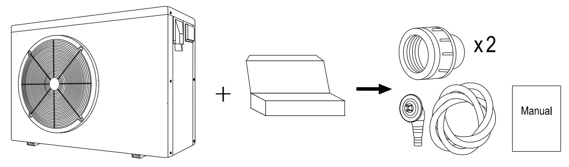
Operating conditions and range:
| Items | Range | |
| Operating range | Air temp | -7℃~43℃ |
| Water temp | 0℃~35℃ | |
| Temp. setting | heating | 18℃-35℃ |
The heat pump will have ideal performance in the operation range Air 15℃~25℃
Advantages of different modes:
The heat pump has two modes: Smart and Silence. They have different advantages under different conditions
| Mode | Recommendation | Advantages |
|
SMART |
As standard | Heating capacity: 20% to 100% capacity Intelligent optimization Fast heating |
| SILENCE
| Use at night | Heating capacity: 20% to 80% capacity
Sound level: 3dB (A) lower than Smart mode. |
- This heat pump has a Power-off memory function. When the power is recovered, the heat pump will restart automatically.
- The heat pump can only be used to heat the pool water. It can NEVER be used to heat other flammable or turbid liquids.
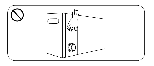
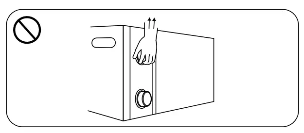
- Don’t lift the water union when moving the heat pump since the titanium heat exchanger inside the heat pump will be damaged.

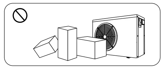
- Don’t put obstacles before the air inlet and outlet of the heat pump.

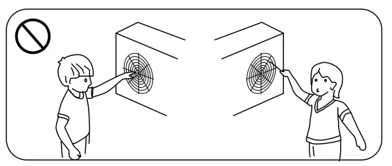
- Don’t put anything into inlet or outlet, or the efficiency of the heat pump will be reduced or even stopped.

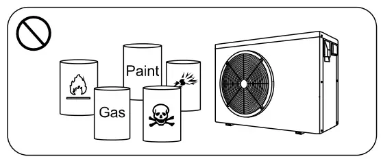
- Don’t use or store combustible gas or liquid such as thinners, paint and fuel to avoid fire.

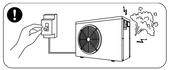
- If any abnormal circumstances occurred, e.g.: abnormal noises, smells, smokes and leakage of electricity, switch off the main power immediately and contact your local dealer. Don’t try to repair the heat pump by yourselves.

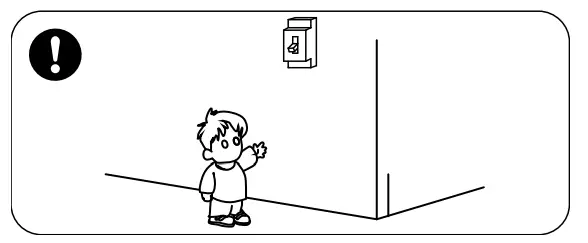
- The main power switch should be out of the reach of Children.

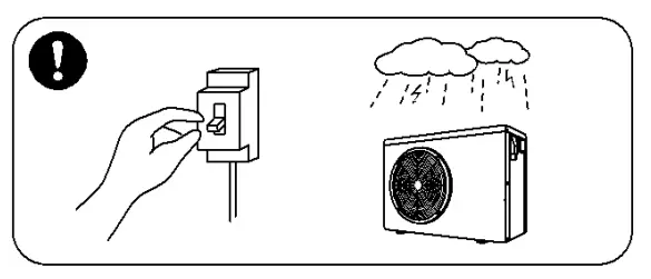
- Please cut off the power in the lightning storm weather.

- Please note that following codes are not failure.
| Codes | |
| Out of the operating range | 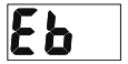 |
| No water | 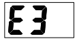 |
| Insufficient water flow or pump blocked | 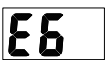 |
| Power abnormal |  |
| Defrosting |  heating light twinkling heating light twinkling |
Operations
Notice before using
- The user is advised to start the water pump before the heat pump, and turn off the heat pump before the water pump for long life circle.
- Check firstly for any water leakage of piping connection, then power on, press the ON/OFF button of the heat pump, and set suitable temperature.
Operation instructions
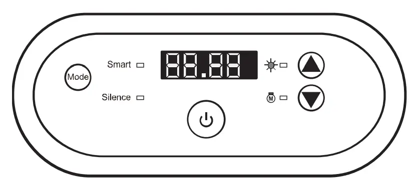
| Symbol | Designation | Operation |
 | Power ON/OFF | Press to power on or off the heat pump |
 | Mode | Press to select Smart/Silence mode |
|
| Up/ Down | Press to set the desired water temperature |

Note:
- You may set the desired water temperature from 18 to 35℃.
- The one
 on the right shows the inlet water temperature. The on the left shows the set temperature by pressing
 buttons at the same time.
 - After you turn on the heat pump, the fan will start to run in 3 minutes. In another 30 seconds, the compressor will start to run.
- During heating, the
 will be light.
Mode selections
- will be light as standard when you turn on the heat pump.
- Press
 the button to enter the Silence mode, they will be light.
 - Press the button again to exit and enter the SMART mode.
Compulsory defrosting
- When the heat pump is heating and the compressor is working continuously for 10 minutes, press both “the” and “ ” buttons for 5 seconds to start compulsory defrosting.
- (Note: the interval between compulsory defrosting should be more than 30 minutes.)
- The heating light will be twinkling when the heat pump is in compulsory or auto defrosting.
- The running process and ending of compulsory defrosting are the same as auto-defrosting.
Daily maintenance and winterizing
Daily Maintenance
Please don’t forget to cut off power supply of the heat pump
- Please clean the evaporator with household detergents or clean water, NEVER use gasoline, thinners or any similar fuel.
- Check bolts, cables and connections regularly.
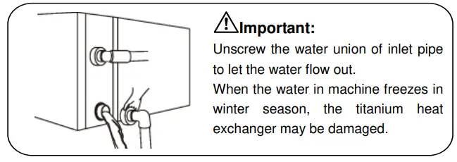
Winterizing
In winter season when you don’t swim, please cut off power supply and drain water out of the heat pump. When using the heat pump under 0℃, make sure that the water pump is always running.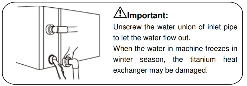
Technical specification
| Model | 34-180139 | 34-180140 |
| Advised pool volume (m3) | 25-50 | 30-60 |
| Working air temp (℃) | -7~43 | |
| Performance Condition: Air 26°C, Water 26°C, Humidity 80% | ||
| Heating capacity (kW) | 11.3~2.8 | 13.3~3.4 |
| Heating capacity (kW) in silence mode | 9.0~2.8 | 10.4~3.4 |
| C.O.P | 15.1~6.5 | 15.0~6.4 |
| C.O.P in silence mode | 15.1~7.5 | 15.0~7.4 |
| Performance Condition: Air 15°C, Water 26°C, Humidity 70% | ||
| Heating capacity (kW) | 7.3~1.9 | 9.4~2.3 |
| Heating capacity (kW) in silence mode | 5.8~1.9 | 7.4~2.3 |
| C.O.P | 7.7~4.5 | 7.6~4.4 |
| C.O.P in silence mode | 7.7~5.2 | 7.6~5.1 |
| Rated input power (kW) | 1.6~0.22 | 2.1~0.25 |
| Rated input current (A) | 7.4~0.95 | 9.1~1.1 |
| Power supply | 230V/1 Ph/50Hz | |
| Advised water flux (m³/h) | 4~6 | 5~7 |
| Sound pressure 1m dB(A) | 39.5~48.2 | 42.8~52.1 |
| Sound pressure 10m dB(A) | 19.5~28.2 | 22.8~32.1 |
| Water pipe in-out Spec (mm) | 50 | |
| Net Dimension LxWxH (mm) | 961×312×658 | 961×312×658 |
| Net Weight (kg) | 50 | 52 |
- The values indicated are valid under ideal conditions: Pool covered with an isothermal cover, filtration system running at least 15 hours a day
- Related parameters are subject to adjustment periodically for technical improvement without further notice. For details please refer to the nameplate.
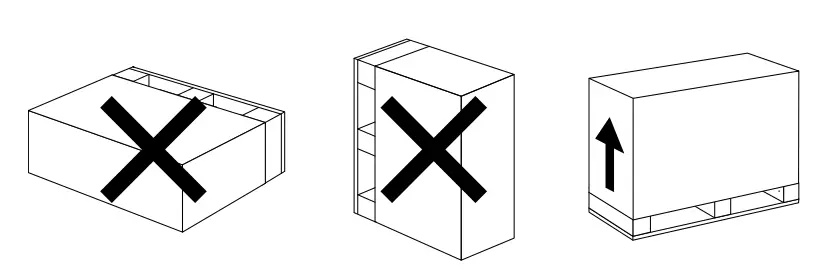
Transportation
- When storing or moving the heat pump, the heat pump should be at the upright

- When moving the heat pump, do not lift the water union since the titanium heat exchanger inside the heat pump will be damaged.

Installation and maintenance
- The heat pump must be installed by a professional team. The users are not qualified to install by themselves, otherwise the heat pump might be damaged and risky for users’ safety.
Notice before installation
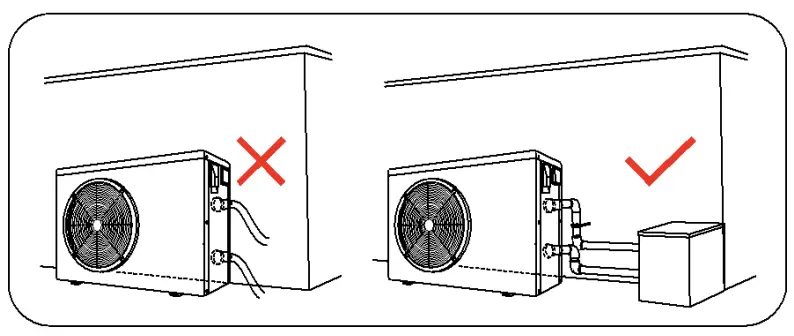
- The inlet and outlet water unions can’t bear the weight of soft pipes. The heat pump must be connected with hard pipes!

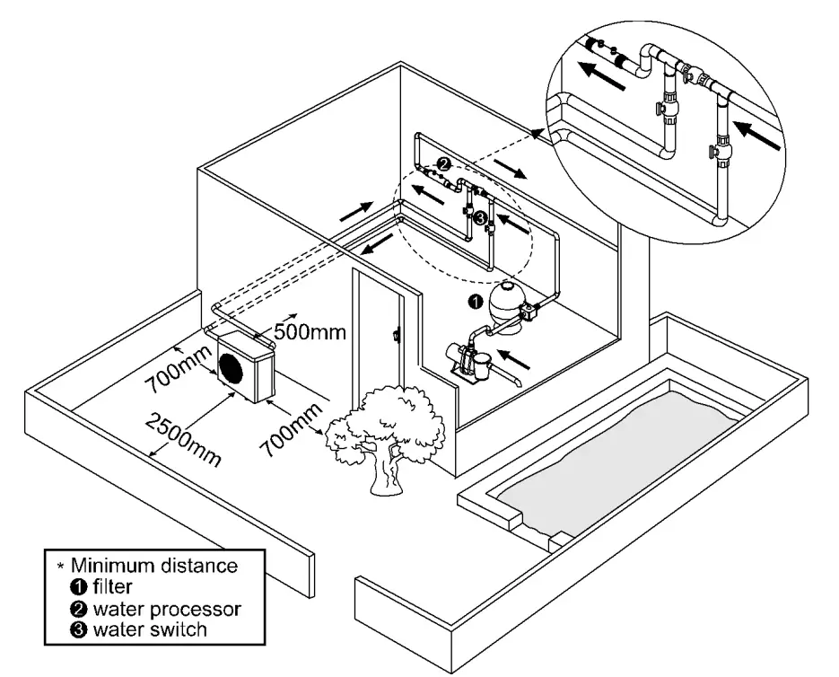
- In order to guarantee heating efficiency, the water pipe length should be ≤10m between the pool and the heat pump.
Installation instruction
Location and size
- The heat pump should be installed in a place with good ventilation

For installers and professionals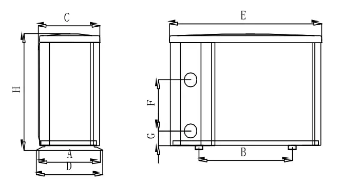
| Size(mm) Model | A | B | C | D | E | F | G | H |
| 34-180139 | 315 | 590 | 312 | 340 | 961 | 340 | 74 | 658 |
| 34-180140 | 315 | 590 | 312 | 340 | 961 | 340 | 74 | 658 |
- The above data is subject to modification without notice.
Heat pump installation.
- The frame must be fixed by bolts (M10) to concrete foundation or brackets. The concrete foundation must be solid; the bracket must be strong enough and anti-rust treated;
- The heat pump needs a water pump (Supplied by the user). The recommended pump specification-flux: refer to Technical Parameter, Max. lift ≥10m
- When the heat pump is running, there will be condensation water discharged from the bottom, please pay attention to it. Please insert the drainage tube(accessory) into the hole and clip it well, then connect a pipe to drain off the condensation water.
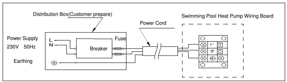
Wiring & protecting devices and cable specification
- Connect to appropriate power supply, the voltage should comply with the rated voltage of the products.
- Well earth the heat pump.
- Wiring must be connected by a professional technician according to the circuit diagram.
- Set breaker or fuse according to the local code (leakage operating current ≤ 30mA).
- The layout of power cable and signal cable should be orderly and not affecting each other.
Wiring diagram
- For power supply: 230V 50Hz

- Note: For your safe use in winter, it’s strongly recommended to equip heating priority function. For the detailed wiring diagram, please refer to Appendix 1.
Options for protecting devices and cable specification
| MODEL | 34-180139 | 34-180140 | |
| Breaker | Rated Current A | 12 | 13 |
| Rated Residual Action Current mA | 30 | 30 | |
| Fuse A | 12 | 13 | |
| Power Cord(mm2) | 3×2.5 | 3×2.5 | |
| Signal cable(mm2) | 3×0.5 | 3×0.5 | |
NOTE: The above data is adapted to power cord ≤ 10m .If power cord is >10m, wire diameter must be increased. The signal cable can be extended to 50m at most.
- Trial after installation
Please check all the wirings carefully before turning on the heat pump.
Inspection before use
- Check installation of the whole heat pump and the pipe connections according to the pipe connecting drawing;
- Check the electric wiring according to the electrical wiring diagram and earthing connection;
- Make sure that the main power is well connected;
- Check if there is any obstacle in front of the air inlet and outlet of the heat pump
Trial
- The user is advised to start the water pump before the heat pump, and turn off the heat pump before the water pump for long life circle.
- The user should start the water pump, and check for any leakage of water; Power on and press the ON/OFF button of the heat pump, and set desired temperature in the thermostat.
- In order to protect the heat pump, the heat pump is equipped with start delay
function. When starting the heat pump, the fan will start to run in 3 minutes, in another 30 seconds, the compressor will start to run. - After pool heat pump starts up, check for any abnormal noise from the heat pump.
- Check the temperature setting
Maintenance and winterizing
Maintenance
- The maintenance should be carried out once per year by qualified professional technician.

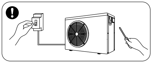
- Cut off power supply of the heat pump before cleaning, examination and repairing . Do not touch the electronic components until the LED indication lights on PCB turn off.
- Please clean the evaporator with household detergents or clean water, NEVER use gasoline, thinners or any similar fuel.
- Check bolts, cables and connections regularly.
Winterizing
In winter season when you don’t swim, please cut off power supply and drain water out of the heat pump. When using the heat pump under 0℃, make sure that the water pump is always running.
Troubleshooting for common faults
| Failure | Reason | Solution |
| Heat pump doesn’t run | No power | Wait until the power recovers |
| Power switch is off | Switch on the power | |
| Fuse burned | Check and change the fuse | |
| The breaker is off | Check and turn on the breaker | |
| Fan running but with insufficient heating | evaporator blocked | Remove the obstacles |
| Air outlet blocked | Remove the obstacles | |
| 3 minutes start delay | Wait patiently | |
| Display normal, but no heating | Set temp. too low | Set proper heating temp. |
| 3 minutes start delay | Wait patiently | |
| If above solutions don’t work, please contact your installer with detailed information and your model number. Don’t try to repair it yourself. | ||
ATTENTION!Please don’t try to repair the heat pump by yourself to avoid any risk.
Failure code
| NO. | Display | Failure description |
| 1 | E1 | High gas pressure protection |
| 2 | E2 | Low gas pressure protection |
| 3 | E3 | No water flow protection (not failure) |
| 4 | E4 | 3 phase sequence protection (only for three phase) |
| 5 | E5 | Outdoor power supply abnormity protection |
| 6 | E6 | Excessive temp. difference between inlet and outlet water(Insufficient water flow protection) |
| 7 | E7 | Protection of low outlet water temperature |
| 8 | E8 | Protection of high exhaust temperature |
| 9 | E9 | Protection of compressor overheat ( reserved) |
| 10 | EA | Protection of evaporator overheat |
| 11 | EB | Ambient temperature too high/low protection |
| 12 | EC | Radiator high temperature protection |
| 13 | ED | Two-level antifreeze (not failure, only available when connecting to heating priority) |
| 14 | P0 | Controller communication failure |
| 15 | P1 | Water inlet temp sensor failure |
| 16 | P2 | Water outlet temp sensor failure |
| 17 | P3 | Gas exhaust temp sensor failure |
| 18 | P4 | Evaporator l temp sensor failure |
| 19 | P5 | Gas return temp sensor failure |
| 20 | P6 | Heat exchanger temp sensor failure |
| 21 | P7 | Ambient temp sensor failure |
| 22 | P8 | Radiator temp sensor failure |
| 23 | P9 | Current sensor failure |
| 24 | PA | Restart memory failure |
| 25 | F1 | Compressor drive module failure |
| 26 | F2 | PFC module failure |
| 27 | F3 | Compressor start failure |
| 28 | F4 | Compressor running failure |
| 29 | F5 | Compressor module over current protection |
| 30 | F6 | Compressor module overheat protection |
| 31 | F7 | Current protection |
| 32 | F8 | Radiator overheat protection |
| 33 | Fb | Capacitor No-power protection |
Appendix 1: Heating priority wiring diagram (Optional)
- For water pump: Voltage 230V, Capacity ≤500W
- For water pump: Voltage 230V, Capacity >500W

- For water pump: Voltage 400V

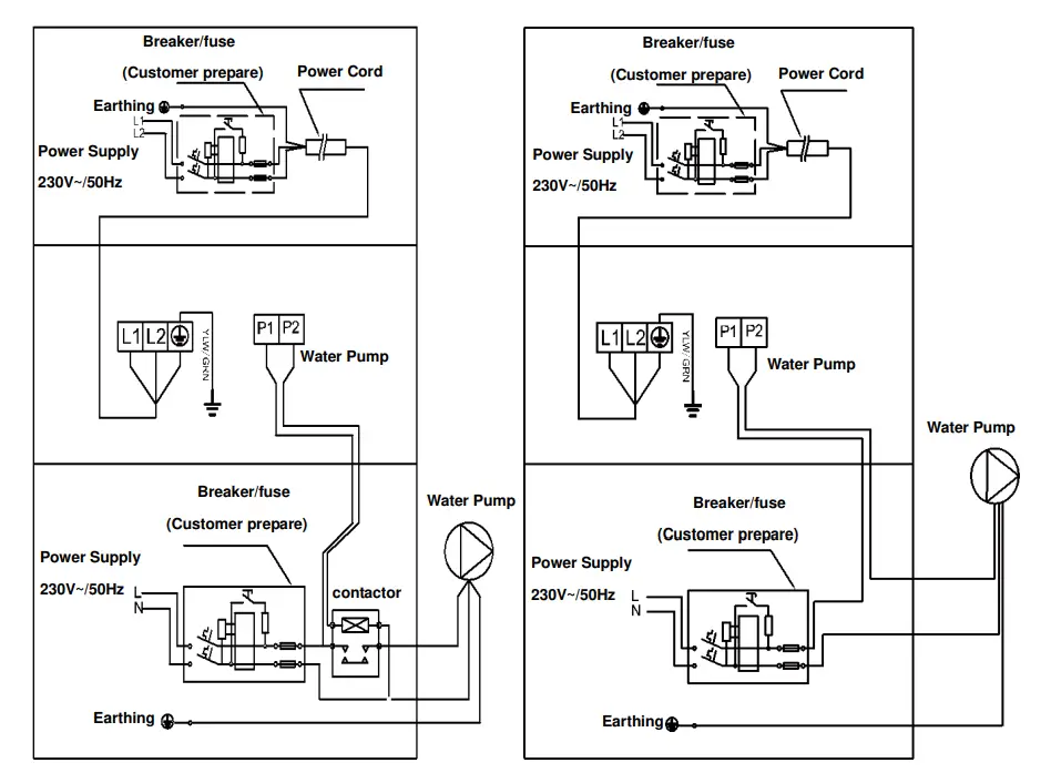
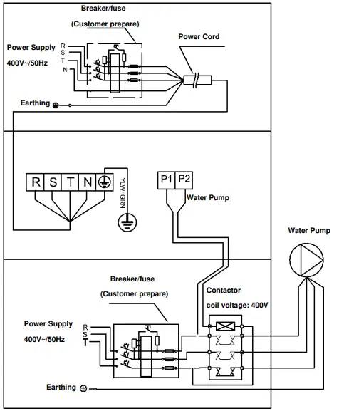
Parallel connection with filtration clock
- A: Water pump timer
- B: Water pump wiring of Heat Pump
- Note: The installer should connect A parallel with B (as above picture). To start the water pump, condition A or B is connected. To stop the water pump, both A and B should be disconnected.


