View QDM-05-000093 Control Panel 5.0 User Guide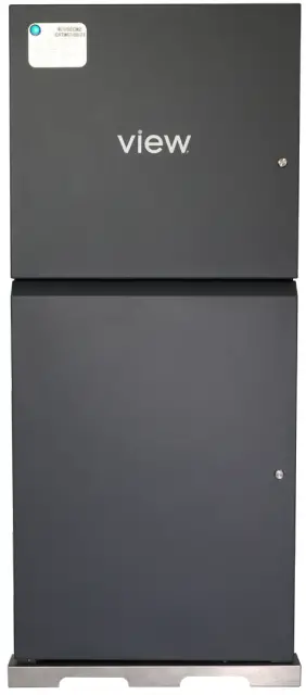
Purpose
The purpose of this Quick Start Guide is to provide explanations and procedures for installing and operating the View Control Panel 5.0 (CP).
Scope
This Guide provides safety guidelines, detailed planning installation instructions and setup information for installing the View Control Panel 5.0.
- Determining the location and placement
- Mounting the Control Panel
- Adding Power to the Control Panel
Package Includes
- Control Panel 5.0 assembly

- Telco Rack (shipped separately)
CAUTION: HEAVY EQUIPMENT When moving and locating the Control Panel use proper lifting equipment and certified rigging personnel.
Work Performed by
Low Voltage and Line Voltage Contractor
- Line voltage contractor: Line voltage for AC power
- Low voltage contractor: All other low voltage connections
Location of Control Panel Installation
Refer to View Interconnect Drawings for exact location and ensure the place of installation is safe and secured.
Contractor Responsibility
- Mount Control Panel to floor and wall
- Provide AC power
- Install iNode server in telco rack
- Install telco rack assembly
Phase of Project
Prewire / Rough-in
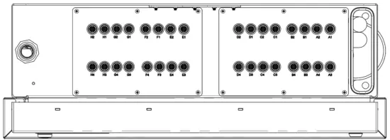
Parts of the Control Panel
The main components in the Control Panel are:
- GAM
- CPHE
- Power Supplies
- PDU
- 3-Phase power block
- Green indicator light on the front door
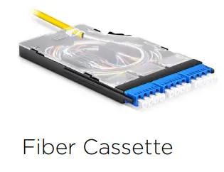
- Telco Rack (Including Fiber and Ethernet switches and fiber cassette drawers)

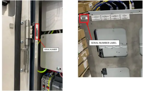
CAUTION: Serial numbers are assigned to the Control Panel and the Telco rack. These items are shipped separately and during assembly the serial number must match, otherwise the system will not work properly.
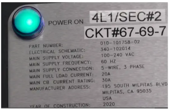
Power Requirements
- Dedicated 30 amp circuit
- 208 V 3 phase 5-wire power
- Critical Power preferred
- Output power is Class 2 48VDC
NOTE: For India, Neutral is required
General Notes
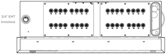
NOTE: Do not remove dust caps from BNC connections on top of Control Panel. These should remain installed until trunk cables are terminated and ready to be connected.
- For all fiber, coaxial cabling, and terminations, refer to View Interconnect Drawing
- Prior to mounting Control Panel, ensure 4” sleeves have been installed in the concrete slab between floors. The sleeves will accommodate vertical fiber cabling between multiple control panels.
- Functional Hardware Testing (FHT) will be completed one control panel at a time.
- Networking of control panels will be completed by View Field Service Engineer (FSE)
- DO NOT connect fiber patch cables to the network switches until the View FSE arrives onsite
Supplied by Installer
- Material handling equipment
- Concrete anchors, wall anchors (per local building codes)
- Torpedo level
- Tape measure
- Power tools
- Other miscellaneous tools as needed
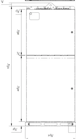
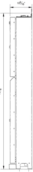
Dimensions
RECEIVING AND HANDLING
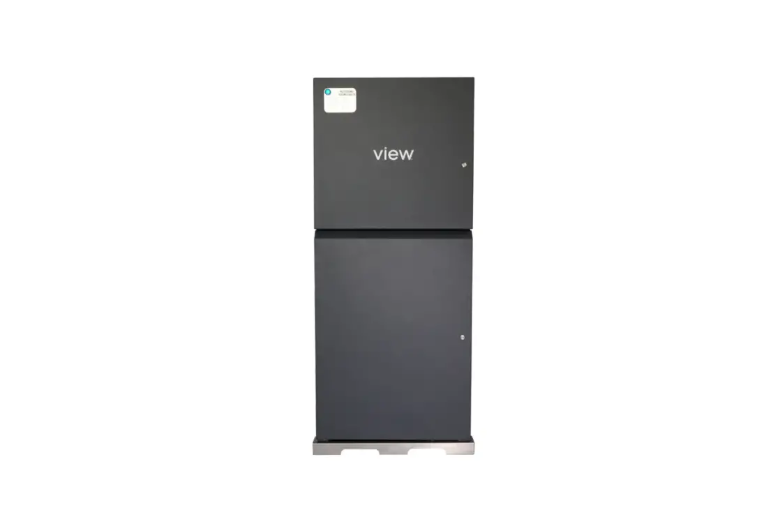
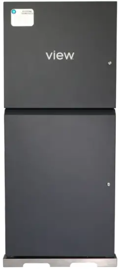
Control Panel 5.0
CP 5.0 In the Box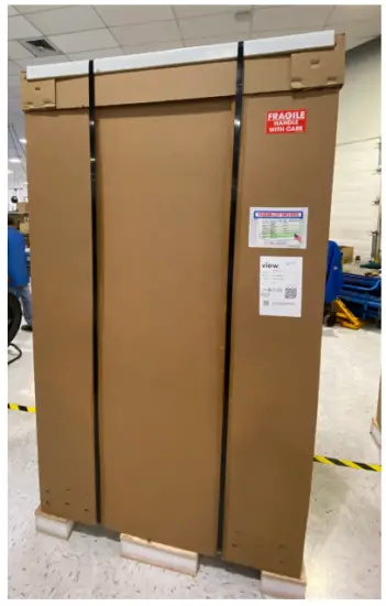
CP 5.0 Unboxed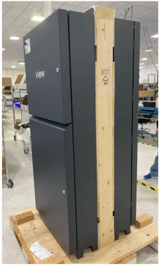
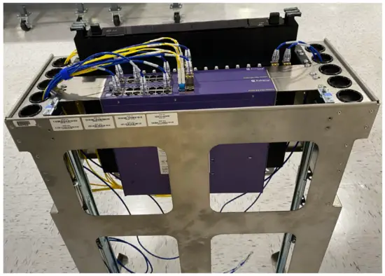
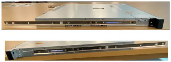
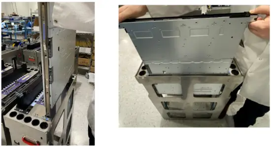
Telco Rack
Telco Rack in Wood Crates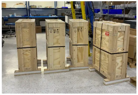
Telco Rack Uncrated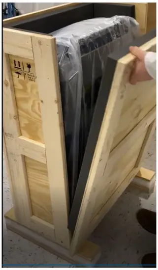
Telco Rack Ready for Install in Control Panel*
*Prior to installing Telco rack in Control Panel,
- iNode server must be installed (Refer to View Interconnect Drawings). When applicable, iNode server ships separately in cardboard box.
- The serial number on the Telco rack and the Control Panel MUST match
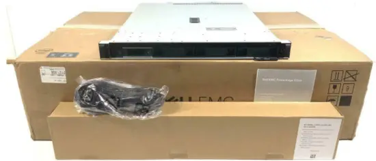
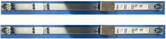
iNode Server(s)
iNode Server In the Box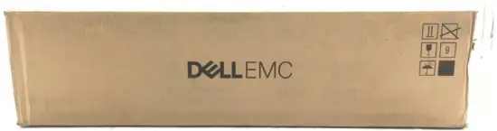
iNode Server ready to be mounted in Telco rack*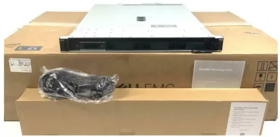
*Low-Voltage contractor is required to install each iNode server into the Telco racks as shown on View interconnect drawings. iNode server(s) must be populated inTelco rack prior to installed in Control Panel.
iNode Server mounted in Telco rack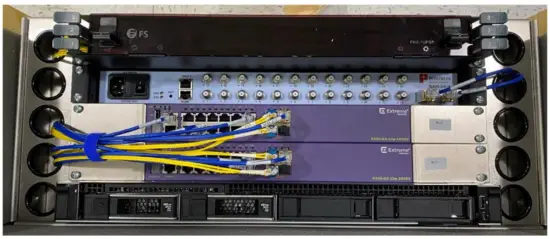
CONTROL PANEL INSTALLATION
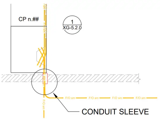
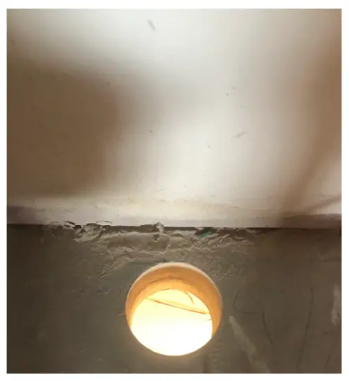
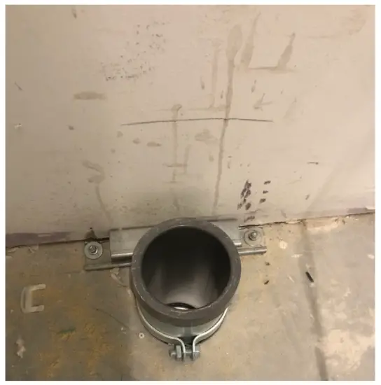
1. The conduit sleeve location must be in-line with the Control Panel’s raceway. Refer to Interconnect Drawings for Control Panel location(s).
- The conduit sleeve between floors is directly below the Control Panel raceway.

The armored fiber cable is routed through the conduit sleeve and into the Control Panel raceway
- Confirm 4” conduit sleeves are installed in the concrete slab between floors. The conduit sleeves will accommodate vertical fiber cable routing between multiple Control panels.
Conduit sleeve diameter must be 4” or more.
When installing floor penetrations in sleeves, stub-out size cannot be more than 2” high.
- Mobilize the Control Panel to location per the View Interconnect Drawings.
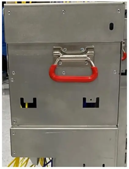
- Use top mounted hook when using a crane otherwise, use material handling equipment or equivalent.
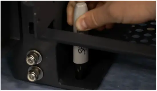
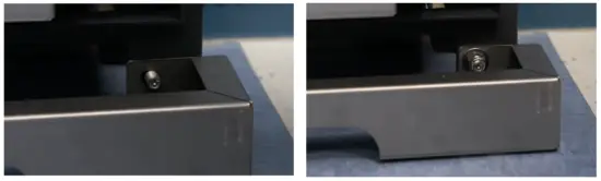
- Using the conduit sleeve as a reference, place the Control Panel directly above the conduit sleeve and mark the floor for the mounting locations at each corner of the Control Panel.

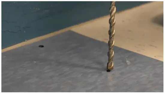
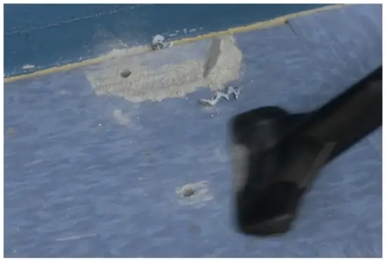
- Move Control Panel and drill four (4) holes at the marked locations using a concrete bit and hammer drill.
Drill marked locations.
Clean debris before installing the Control Panel.
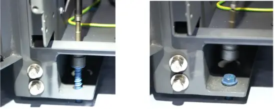
- Return Control Panel to installation location so that floor and wall penetratations lineup with mounting points. Ensure that Control Panel is plum and level.

- Hold the top part of the Control Panel while fastening the bottom to the floor to ensure it does not tip over
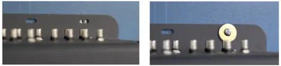
- Insert and drill floor anchor bolts to mounting locations

- Insert and drill wall anchor bolts to mounting locations

- Install bottom kickplate to the base of the Control Panel

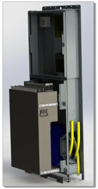
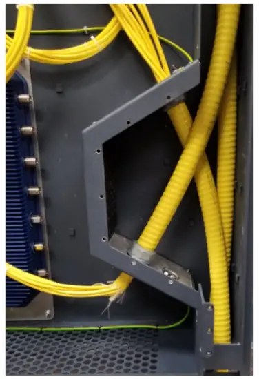
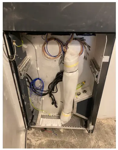
- Rough-In / Prewire Fiber into CP 5.0
- Run Backbone fiber into raceway through the top of the CP 5.0

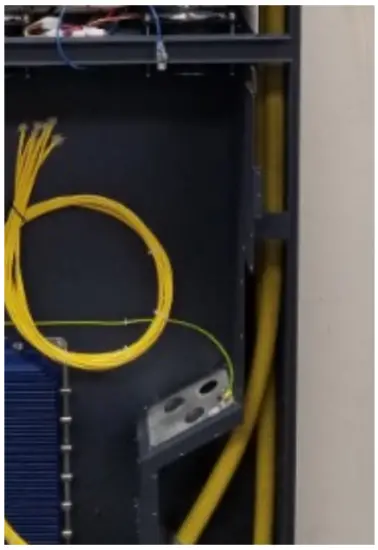
- Run fiber from top raceway into lower gland port. Strip away outer armor jacket (10 feet) and secure for later termination.

- Run fiber from lower gland port into upper gland port. Strip away outer armor jacket (10 feet) and secure for later termination.

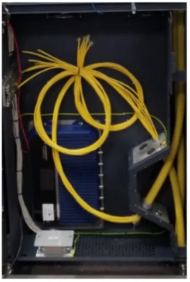
- Final rough-in configuration

- Run Backbone fiber into raceway through the top of the CP 5.0
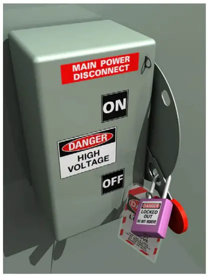
- Lock Out Tag Out (LOTO) procedure before power to CP5.0
- LOTO: Main power breaker from the building supplying power to View Control Panel. NOTE: Follow OSHA LOTO procedures before installing power to Control Panel.

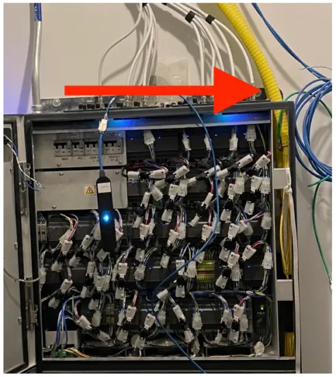
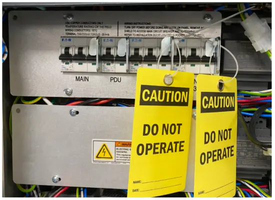
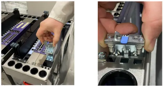
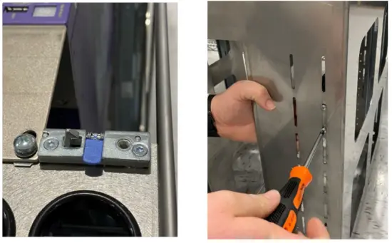
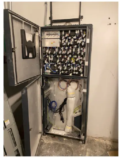
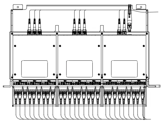
- LOTO: VIEW NET 1-16 & VIEW NET 17-32: Zip tie a
LOTO tag to each of the levers shown in Image #2.
The LOTO tag can be installed by the low-voltage contractor or a View technician. Be sure to fill out the tag with technician name and phone number.
CAUTION: Only a View technician is authorized to remove LOTO tags. - When to Energize VIEW NET 1-16 and VIEW NET 17-32 circuits: Once the Control Panel and associated
iNode is fully provisioned, the low-voltage contractor will contact View PM/FSE about removing tags and energizing the circuits.
- LOTO: Main power breaker from the building supplying power to View Control Panel. NOTE: Follow OSHA LOTO procedures before installing power to Control Panel.
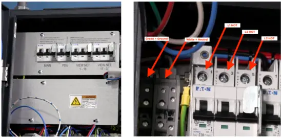
- Connect line voltage 3-phase power to the Control Panel, critical power preferred (Wiring to be completed by a Licensed Electrician)
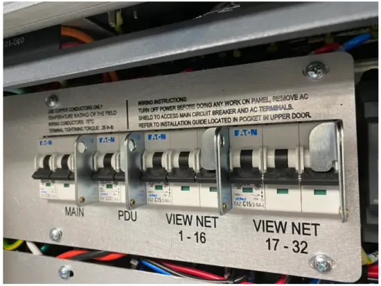
- Remove circuit breaker cover panel
- Install conduit at top of CP 5.0, 3/4” fitting is top left
- Terminate 3-phase power into the terminal blocks starting with ground, then neutral, then the 3-phase power lines
- Punch out a 3/4” EMT knock out at the top of Control Panel

Breaker cover panel Ground, Neutral, L1 Hot, L2 Hot, L3 Hot
- Energize power to Control Panel using LOTO procedures
- Using a Volt/Ohm meter, check proper voltages between Ground, Neutral, L1, L2, and L3
- Verify all internal CP connections: power and data connections. Refer to below procedure and addendum.
- Re-install breaker panel cover after ALL power has been terminated
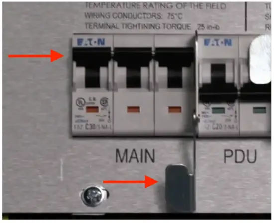
- On the breaker panel, flip the main 3 phase power breaker to the ON position
- Verify the power indicator light is green on the front of the control panel
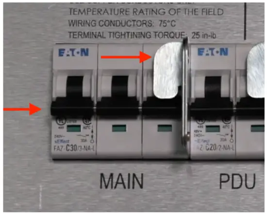
- Install LOTO on the Control Panel’s main circuit breaker. NOTE: Power should be turned OFF for the remainder of work
Power OFF
DO NOT TOUCH
PDU BREAKER SWITCH
Power ON
DO NOT TOUCH
PDU BREAKER SWITCH
Power Indicator Light = Green
- Connect all AC power cables from the devices in the Control Panel to the PDU (Power Distribution Unit). Ensure that power lights are illuminated on all the devices

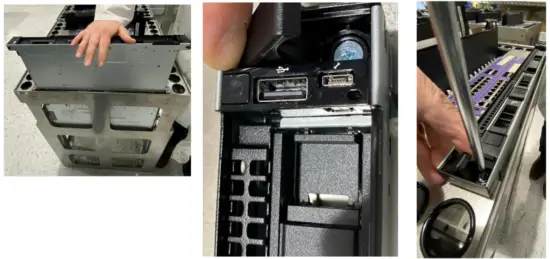
- Populate and Install the Telco Rack
- Unbox Telco rack and verify the serial number matches the serial number on the Control Panel
CAUTION: Serial numbers are assigned to the Control Panel and the Telco rack. These items are shipped separately and during assembly the serial number must match otherwise, the system will not work properly
- Unbox iNode

- Install iNode server in open slot of Telco rack under network switches

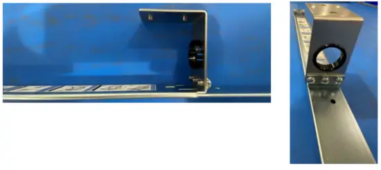
- Install assembled mating guide rails into Telco rack


- Install guide rails onto left and right side of iNode server

- Assemble brackets for installation

- Once guide rails are mated, gently push iNode toward the telco base until the iNode is seated on telco base
- Expose embedded screws at both ends of iNode server and secure


CAUTION
DO NOT PUT YOUR FINGERS UNDER iNode HEADER WHILE PUSHING IT TOWARD THE TELCO BASE. - Telco rack is now completed and is ready to install in Control Panel

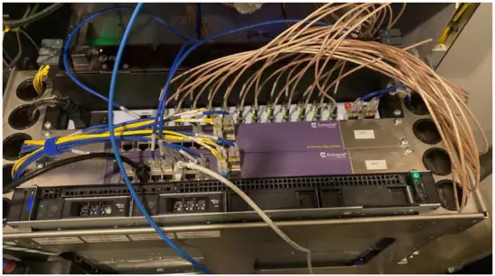
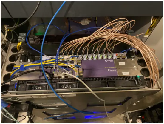
- Connect network cabling from iNode server to network switch. Contact View PM for latest Reference
Document:
View Net CP5 Schematic (ECO-340- 102014)
- Install Telco rack into the sliding rails using red lifting handles in the Control Panel

- Unbox Telco rack and verify the serial number matches the serial number on the Control Panel
- Power ON Control Panel: Ready for Commissioning
- Confirm completion of CP installation with View Project Manager or Project Engineer before proceeding
- Remove LOTO from Building Main Breaker
- Remove LOTO from CP Main circuit breaker
- Power On Control Panel for Functional Hardware Testing (FHT) and provisioning by:
1) Power ON Main Breaker; 2) Power ON PDU breaker - When multiple CPs are installed on a site only one iNode can be powered on at a time during provisioning process
- Refer to Interconnect drawings for iNode server locations
- For CPs with iNodes installed: Upon installation, all iNodes must have the 3-prong power cable removed from the back of the server unit. When provisioning a specific CP, the iNode connected to the CP should be powered ON for the duration of provisioning. Once provisioning is complete, disconnect the iNode power cable before moving to the next CP/ iNode.
- Confirm LOTO tag removal of VIEW NET 1-16 AND VIEW NET 17 32 circuit breakers.
- Power ON View Net circuit breakers
- Begin commissioning process with View Project Engineer

For more information:
Contact your View Project Manager or View Project Engineer
APPENDIX
- Sample Installation
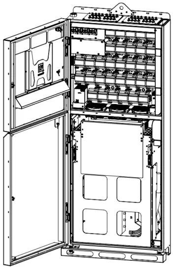
CP 5.0 Chassis Only
CP 5.0 Lower Section for TELCO Rack
CP 5.0 Telco Rack
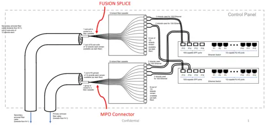
- Fusion Splicing
Vertical Fiber Connections for Control Panel – Top Floor
(Simplified drawing, minimal configuration not showing optional horizontal fiber)
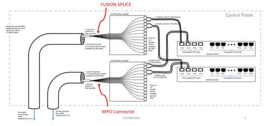
Vertical Fiber Connections for Control Panel – Top Floor
(Simplified drawing, minimal configuration not showing optional horizontal fiber)
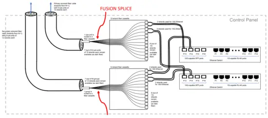
Vertical Fiber Connections for Control Panel – Bottom Floor
(Simplified drawing, minimal configuration not showing optional horizontal fiber)


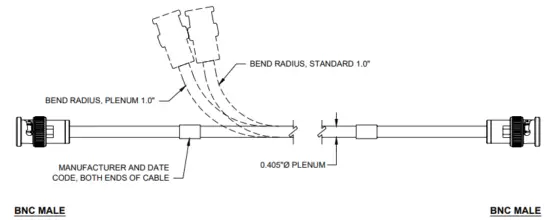
FIELD TERMINATED TRUNK ( LM-400 COAX ) CONNECTION
| VN-DCP-TOXX | VIEW NET COAXIAL DROP CABLE, PLENUM RATED, TERMINATED, X FOOT |
| VN-DCP-UO5 | VIEW NET COAXIAL DROP CABLE, PLENUM RATED, 5OOFT |
| VN-DCP-U1O | VIEW NET COAXIAL DROP CABLE, PLENUM RATED, 1OOOFT |
| VN-DC-OXX | VIEW NET COAXIAL DROP CABLE, TERMINATED, X FOOT |
| VN-DC-UO5 | VIEW NET COAXIAL DROP CABLE, 5OOFT |
| VN-DC-U1O | VIEW NET COAXIAL DROP CABLE, 1OOOFT |
FIBER OPTIC CABLE

| PRETERMINATED WITH MPO CONNECTORS | |
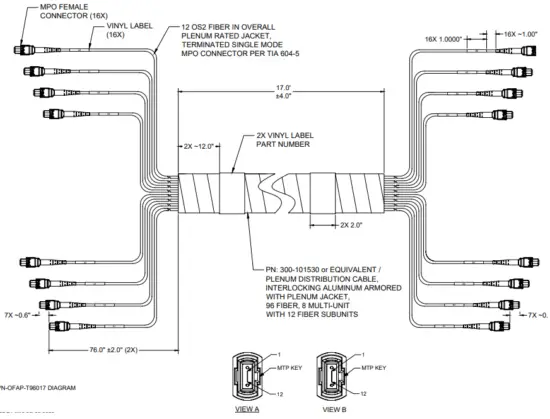
| VN-OFAP-T96017 | OPTICAL FIBER, SINGLE MODE, 0S2, ARMORED, PLENUM RATED, 96 STRANDS TOTAL, EIGHT BUNDLES OF 12 STRANDS EACH, TERMINATED TO MPO CONNECTORS PER TIA 604-5, 10-17 FT INTER FLOOR SPACING |
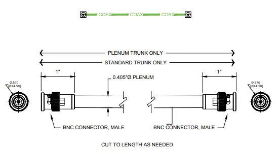
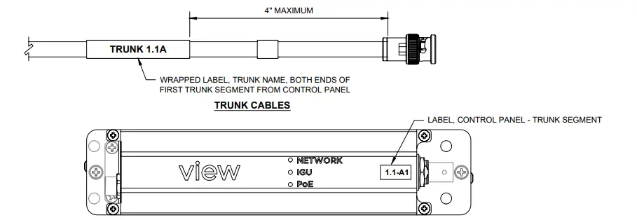
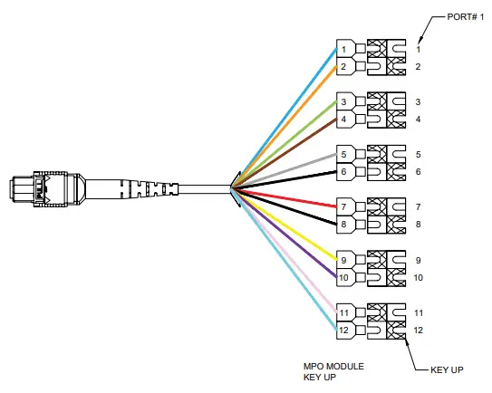
TRUNK CORDSET DETAIL AND DESCRIPTION LIST
Cable pinout
| VN-TCP-U05 | VIEW NET COAXIAL TRUNK CABLE, PLENUM RATED, 500FT SPOOL |
| VN-TCP-U10 | VIEW NET COAXIAL TRUNK CABLE, PLENUM RATED, 1000FT SPOOL |
| VN-TC-U05 | VIEW NET COAXIAL TRUNK CABLE, 500FT SPOOL |
| VN-TC-U10 | VIEW NET COAXIAL TRUNK CABLE, 1000FT SPOOL |
| General Specifications | |
| Armor Type | Interlocking aluminum |
| Cable Type | Distribution |
| Construction Type | Armored |
| Fiber Type, quantity | 96 |
| Fibers per Subunit, quantity | 12 |
| Jacket Color | Yellow |
| Subunit Type | Gel•free |
| Subunit, quantity | 8 |
| Total Fiber Count | 96 |
| Dimensions | |
| Buffer Tube/Subunit Diameter | 5.77 mm I 0.227 in |
| Diameter Over Armor | 29.85 mm I 1.175 in |
| Diameter Over Jacket | 31.9 mm I 1.256 in |
| Mechanical Specifications | |
| Minimum Bend Radius, loaded | 638 mm I 25.118 In |
| Minimum Bend Radius, unloaded | 446 mm I 17.559 in |
| Tensile Load, long term, maximum | 400 N I 89.924 ibf |
| Tensile Load, short term, maximum | 1335 N I 300.12 lbf |
| Compression | 85 Wmm 1485.363 lb/in |
| Compression Test Method | FOTP-41 I IEC 60794-1 E3 |
| Flex | 25 cycles |
| Flex Test Method | FOTP-104 I IEC 607941 E6 |
| Impact | 35 N-m I 309.776 in lb |
| Impact Test Method | FOTP-25 I IEC 60794-1 E4 |
| Strain | See long and short term tensile loads |
| Strain Test Method | FOTP-33 I IEC 60794-1 El |
| Twist | 10 cycles |
| Twist Test Method | FOTP-85 I IEC 60794-1 E7 |
| Vertical Rise, maximum | 48 m I 157.48 ft |
| Optical Specifications | |
| Fiber Type | G.652.DIG.652.0 and G.657A1. TeraSPEECO |
| Environmental Specifications | |
| installation temperature | 0 ‘C to ,70t (+32 ‘I to •158 ‘F) |
| Operating Temperature | -20 t to +70’C (-4 ‘F to +158 ‘F) |
| Storage Temperature | -40 ‘C to +70 ‘C (-40’F to •158 ‘F) |
| Cable Qualification Standards | ANSI/KEA S-83-5961 Telcordla GR-409 |
| Environmental Space | Plenum |
| Flame Test Listing | NEC OFCP (ETL) and c(ET1) |
| Flame Test Method | NFPA 130 I NFPA 262 |
| Environmental Test Specifications | |
| Heat Age | -20’C to +85 ‘C (-4 ‘F to +185 ‘F) |
| Heat Age Test Method | IEC 60794-1 F9 |
| Low High Bend | -20’C to +70’C (-4 ‘F to +158 ‘F) |
| Low High Bend Test Method | FOTP-37 I SEC 60794-1 Eli |
| Temperature Cycle | -20’C to +70’C (-4 ‘F to +158 ‘F) |
| Temperature Cycle Test Method | FOTP-3 I IEC 60794-1 Fl |
| Packaging and Weights | |
| Cable weight | 847 kg/km 1569.158 lb/kft |
- VIEW OFFERS ARMORED 12 AND 96 STRAND SINGLE MODE FIBER (SMF)
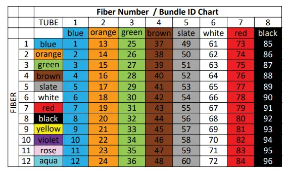
- 12 STRAND ARMORED FIBER HAS 12 INDIVIDUAL COLOR CODED ‘BUFFER CLAD’ FIBERS
- 96 STRAND ARMORED FIBER HAS 8 SUBUNITS (MARKED). EACH WITH 12 BUFFER CLAD FIBERS
- THE SUBUNITS ARE MARKED ON THE JACKET OF THE SUBUNIT EVERY 0.5 M
- FOR 96 STRAND FIBER, EACH SUBUNIT SHOULD HAVE A FREE LENGTH OF 76″ ONCE INSIDE THE CABINET
FIBER SPOOL – UNTERMINATED
VN-OFAP-1205 OPTICAL FIBER, SINGLE MODE, 0S2, ARMORED, PLENUM RATED, 12 STRAND, 500FT SPOOL
VN-OFAP-1210 OPTICAL FIBER, SINGLE MODE, 0S2, ARMORED, PLENUM RATED, 12 STRAND, 1000FT SPOOL
VN-OFAP-96025 OPTICAL FIBER, SINGLE MODE, 0S2, ARMORED, PLENUM RATED, 96 STRAND, 250FT SPOOL
VN-OFAP-9605 OPTICAL FIBER, SINGLE MODE, 0S2, ARMORED, PLENUM RATED, 96 STRAND, 500FT SPOOL
VN-OFAP-9610 OPTICAL FIBER, SINGLE MODE, 0S2, ARMORED, PLENUM RATED, 96 STRAND, 1000FT SPOOL
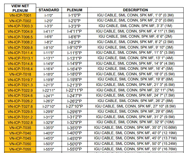
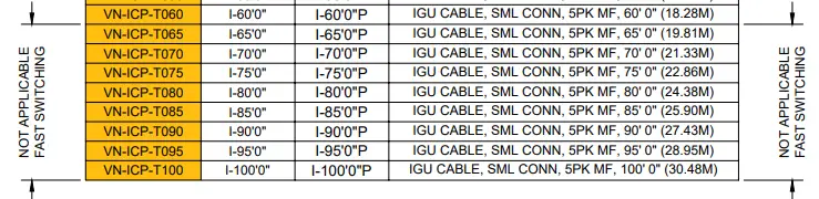
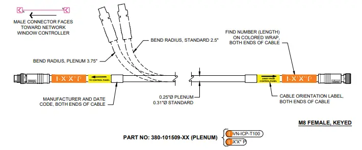
IGU Cordset detail and description list
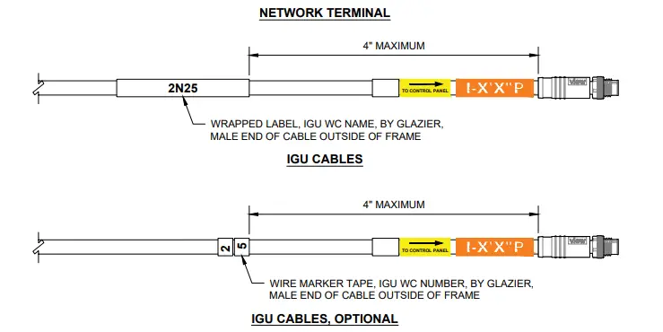

- MACHINE PRINTED LABEL SHOULD BE LOCATED WITHIN e OF CABLE END.
- EACH LABEL SHOULD BE MACHINE PRINTED – BLACK PRINT ON WHITE MATERIAL.
- USE PROPORTIONAL FONT, MINIMUM 14 PT BOLD.
- CABLE IDENTIFIER SHOULD APPEAR TWO TIMES ON THE LABEL FOR VISIBILITY.
- LABELS SHOULD BE OF PERMANENT TYPE MATERIAL.
- HAND WRITTEN LABELS SHOULD NOT BE USED.
- DO NOT MAKE LABELS FROM MASKING TAPE, ELECTRICAL TAPE, DUCT TAPE, PAPER COVERED SCOTCH TAPE OR ANY NON LABEL MATERIAL.
- WIRE MARKER TAPE CAN BE USED FOR IGU CABLES. USE NUMBER TO MATCH !GU MARKING ON INTERCONNECT.
- LABELS AND MARKER TAPE NOT PROVIDED BY VIEW.
- TESTED LABEL, PROVIDED BY VIEW, TO BE PLACED ON EACH END OF CABLE AFTER INSTALLATION AND TESTING.
Fusion Splicing
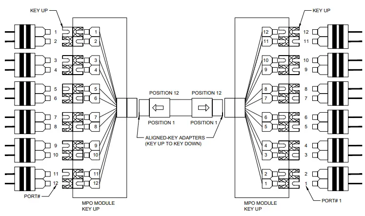
- 96-strand fiber: Individual subunit bundles are numbered 1 thru 8 from MFG
- Use BICSI industry standards for fusion splicing cassettes, see color mapping table on this page
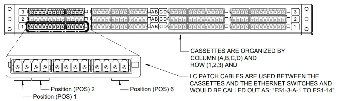
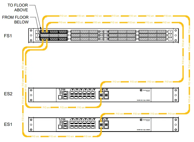
E.g; Storage drawer 1. Row 3, Column A, Position 1 to switch 1 port 14
Fiber Enclosure elevation – 96 port landing
- TERMINATING ALL 96 STRANDS OF A FIBER BUNDLE REQUIRES 8 CASSETTES PER BUNDLE.
- VIEW SUPPLIES TWO CASSETTES PER CP. ONE TO TERMINATE 12 STANDS COMING FROM THE FIBER BUNDLE TO THE FLOOR BELOW AND ONE FOR TERMINATING 12 STRANDS TO THE FLOOR ABOVE. ADDITIONAL CASSETTES MUST BE SPECIFIED IN A SALES ORDER
| FIBER STORAGE | DRAWER | ROW | COLUMN | POSITION | ETHERNET SWTICH | PORT |
| FS | 1 | 3 | A | 1 | ES1 | 14 |
| FS | 1 | 3 | A | 2 | ES2 | 14 |
| FS | 2 | 3 | A | 1 | ES1 | 13 |
| FS | 2 | 3 | A | 2 | ES2 | 13 |
Note: Typical details – Not all shown may apply to this project
- VIEW UTILIZES OPTICAL FIBER FOR INTERCONNECTING VIEW NET CABINETS.
- NEVER LOOK INTO AN END OF A FIBER, THE LIGHT TRANSMITTED IS IN THE INFRARED SPECTRUM (1310NM) AND NOT VISIBLE TO YOUR EYE.
- ALWAYS KEEP CAPS ON UNUSED PORTS OR FIBER PATCH CORDS.
- THE TIPS OF THE FIBER CONNECTOR ARE FINELY POLISHED AND NEED TO BE PROTECTED FROM DUST AND DIRT. IF YOU NEED TO UNPLUG A FIBER, BE SURE TO CAP IT, BOTH FOR SAFETY AND THE HEALTH OF THE FIBER CONNECTION.
- IF YOU WANT TO TROUBLESHOOT AN OPTICAL NETWORK, USE THE PROPER TOOLS LIKE A VISUAL FAULT INDICATOR OR OPTICAL POWER METER.
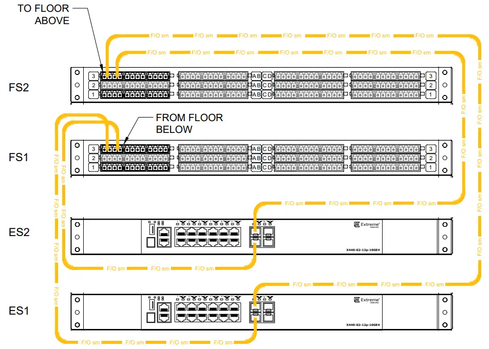
Fiber Routing – Two storage enclosure
| FIBER STORAGE | DRAWER | ROW | COLUMta | POSITION | ETHERNET SWTICH | PORT |
| FS | 1 | 1 | A | 1 | ES1 | 14 |
| FS | 1 | 1 | A | 2 | ES2 | 14 |
| FS | 1 | 3 | A | 1 | ES1 | 13 |
| FS | 1 | 3 | A | 2 | ES2 | 13 |
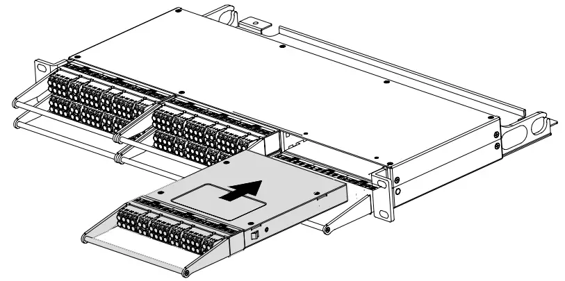
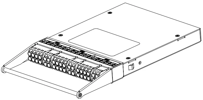
Ultra high density cassette w/MTP connection
ULTRA HIGH DENSITY FIBER ENCLOSURE 1 RU
ULTRA HIGH DENSITY MTP CASSETTES (UP TO 6)
ULTRA HIGH DENSITY FIBER ENCLOSURE
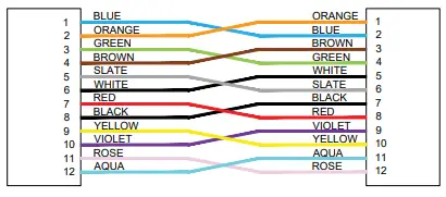
- WHEN FUSION SPLICING BULK FIBER THE STANDS MUST BE CONNECTED IN THE PATTERN SHOWN ABOVE.
- THIS PATTERN IS NECESSARY TO ENSURE TRANSMITTING FIBERS ARE CONNECTED TO RECEIVING FIBERS AND THE POSITIONAL ORDER OF THE FIBER IN THE CASSETTE IS MAINTAINED (E.G. POS1 FROM ONE END TERMINATES ON POS1 ON THE OPPOSITE END, AND WITH THE CORRECT RECEIVE AND TRANSMIT CONNECTIONS


