![]() INSTALLATION, OPERATION AND MAINTENANCE MANUAL
INSTALLATION, OPERATION AND MAINTENANCE MANUAL
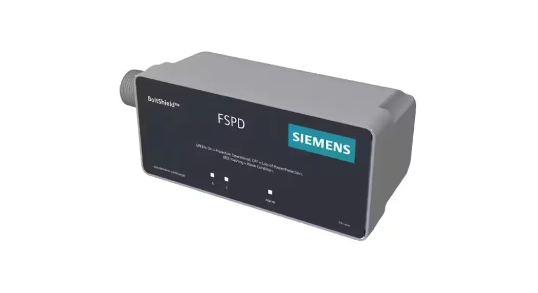
Surge Protection Devices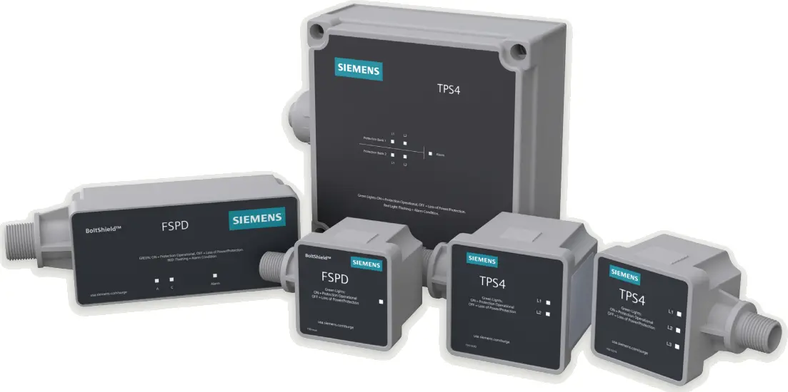 FSPD, TPS4 03, TPS4 09, TPS4 11
usa.siemens.com/spd
Installation Instructions
DANGER
Hazardous Voltage
Will cause death or serious injury.
Turn off power before working on this equipment
WARNING Safety First – Hazardous Voltage and Shock Hazard
- Only qualified licensed electricians should install or service SPDs
- Hazardous voltages exist within SPDs
- SPDs should never be installed or serviced when energized
- Use appropriate safety precautions including Personal Protection Equipment
- Failure to follow these instructions can result in death, serious injury, and/or equipment damage
- This manual shall be read in its entirety prior to installing
Bonding and Grounding Hazard
Verify that the neutral conductor in the service entrance equipment is bonded to ground in accordance with the National Electric Code (NEC®) and all applicable codes. During installation into an electrical system the SPD must not be energized until the electrical system is completely installed, inspected and tested. All conductors must be connected and functional including the neutral (if required). The voltage rating of the SPD and system must be verified before energizing the SPD. Failure to follow these guidelines can lead to abnormally high voltages at the SPD. This may cause the SPD to fail. The warranty is voided if the SPD is incorrectly installed and/or if the neutral conductor in the service entrance equipment or downstream of separately derived systems is not bonded to ground in accordance with the NEC®.
Do Not Hi-Pot Test SPDs
Any factory or on-site testing of power distribution equipment that exceeds normal operating voltage such as high-potential insulation testing, or any other tests where the suppression components will be subjected to higher voltage than their rated Maximum Continuous Operating Voltage (MCOV) must be conducted with the SPD disconnected from the power source. For 4-wire systems, the neutral connection at the SPD must also be disconnected prior to performing high-potential testing. Failure to disconnect SPD and associated components during elevated voltage testing will damage the SPD and will void the warranty.
SPDs on Ungrounded Systems
Caution – Ungrounded systems are inherently unstable and can produce excessively high line-tog round voltages during certain fault conditions. During these fault conditions, any electrical equipment including an SPD may be subjected to voltages which exceed their designed ratings. An SPD designed specifically for Ungrounded systems should be used.
Unpacking and Preliminary Inspection
Inspect the entire shipping container for damage or signs of mishandling. Remove the packing materials and further inspect the unit for any obvious shipping damages. If any damage was found and is a result of shipping or handling, immediately file a claim with the shipping company and contact Siemens customer support.
Storage Environment
This SPD should be stored in a clean, dry environment. Storage temperature range is -40°C (-40°F) to +60°C (+140°F). Avoid exposure to high condensation.
FSPD Catalog Logic
| Catalog ID | Surge Current (kA) |
| FSPD036 | 36kA |
| FSPD060 | 60kA |
| FSPD100 | 100kA |
| FPSD140 | 140kA |
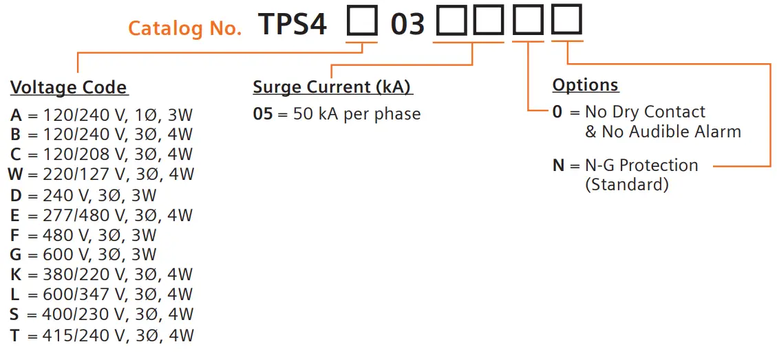
TPS4 03 Catalog Logic
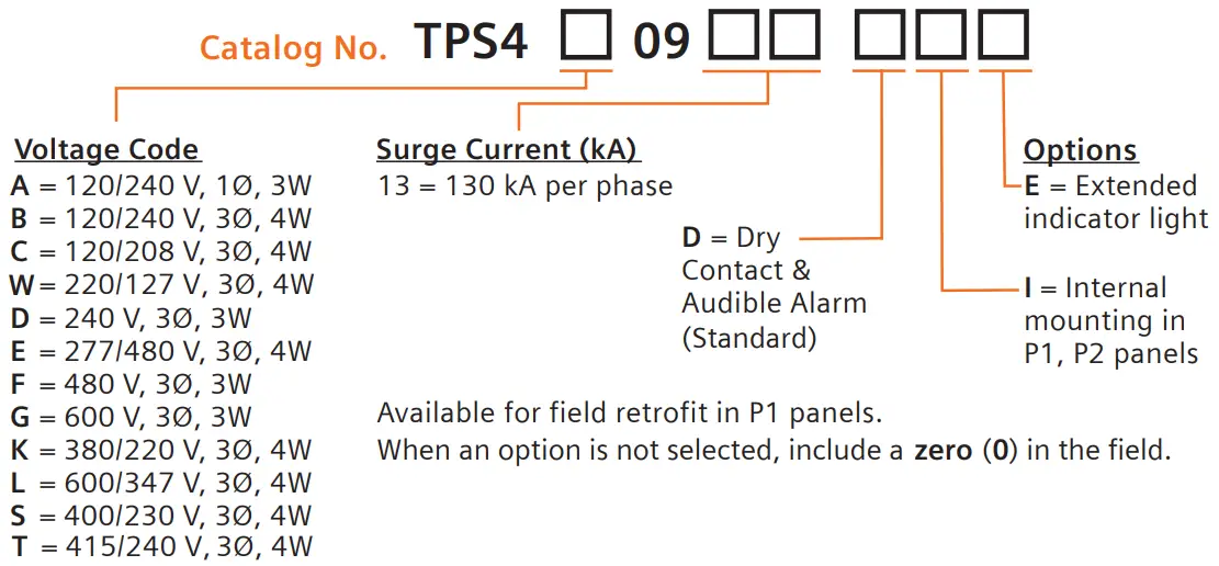
TPS4 09 Catalog Logic
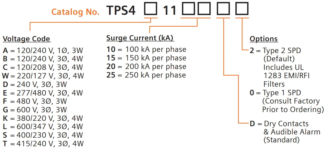
TPS4 11 Catalog Logic
Pre-Installation and Installation Planning
Operating Environment
The standard unit uses a NEMA 4X enclosure. Flush-mount kits are available as options. Before installing, ensure that your enclosure type and application are appropriate with regard to moisture, dirt, excessive dust, flammable materials or atmospheres, corrosive vapors, etc. Please consult factory if enclosure needs to be changed. This SPD is designed in an ambient temperature range of -40°C (-40°F) to +85°C (+185°F) with a relative humidity of 0% to 95% (noncondensing).Excessive temperature may inadvertently operate internal thermal over temperature protectors.
Line Side versus Load Side Installation
The FSPD Series is tested and qualified as a Type 2 SPD per UL 1449 4th Ed. The TPS4 03 and 09 series are tested and qualified as a Type 1 SPD. This SPD can be installed on the Line Side of the service overcurrent device. Type 1 SPDs may also be installed in UL Type 2 applications. The TPS4 11 series is tested and qualified as both Type 1 and 2 SPD. As a generalization, it is more practical to install as Type 2 on load side of main overcurrent device for maintenance reasons.
Audible Noise
SPD background noise is negligible or non-existent, and does not restrict the location of installation.
Lead Lengths and Maximizing SPD Performance
SPDs must be located as close to the circuit as possible to minimize parasitic losses. Use the shortest and straightest possible leads. Pre-Plan installations and ensure that nearest breaker positions are used. If new construction, adjust breaker locations as appropriate. When longer leads are unavoidable, gently twist leads together (one to two twists per foot), or tie-wrap leads together.
Voltage Rating
Before installing SPD, verify that it has the same voltage rating as the power distribution system. Compare the SPDs nameplate voltage or model number and ensure that SPD configuration matches the intended power source.
Circuit Breaker Connected
When connected on load side of main disconnect, we suggest connecting via a 20-30A circuit breaker. The circuit breaker is the intended disconnect switch and provides short circuit protection to the connecting conductors. These SPDs have internal overload protection elements within the product. These SPDs have demonstrated 200kA Short Circuit Current Ratings (SCCRs).
System Grounding
An equipment grounding conductor must be used on all electrical circuits connected to the SPD. For the best performance, use a single point ground system where the service entrance grounding electrode system is connected to and bonded to all other available electrodes, building steel, metal water pipes, driven rods, etc. (for reference see: IEEE Std 142-2007). For sensitive electronics and computer systems, we recommend that the ground impedance measurement be as low as possible. When metallic raceway is used as an additional grounding conductor, an insulated grounding conductor should be run inside the raceway and sized per the NEC®. Adequate electrical continuity must be maintained at all raceway connections. Do not use isolating bushings to interrupt a metallic raceway run. A separate isolated ground for the SPD is NOT recommended. Proper equipment connections to grounding system and ground grid continuity should be verified via inspections and testing on a regular basis as part of a comprehensive electrical maintenance program. On 4-Wire Power Systems, neutral to ground bonding (Main Bonding Jumper) must be installed per the NEC®. Failure to do so WILL damage SPDs.
Retro-fit Into Existing Panel with No Available Breaker Positions
Follow all applicable Codes:
Consider consolidating loads in a manner that might free breaker positions. A ten foot tap rule in NEC® 240.21(B)(1) allows you to tap the bus as long as the tap conductors are rated at least 10% of the ampacity of the panel. In the case where the ampacity of the panel is larger than the wires of the SPD, consider tapping the bus per NEC® 240.21(B)(1) and running appropriate size conductors to a safety switch fused to 30A. Mount the SPD immediately adjacent to the safety switch.
Installation
Pre-Plan your installation
- Meet all National and Local codes. (NEC® Article 285 addresses SPDs)
- Mount SPD as close to panel or equipment as possible to keep leads short
- Ensure leads are as short and straight as possible, including neutral and ground.
- Consider a breaker position that is closest to the SPD and the panel’s neutral and ground
- Suggested breaker size is 30A-20A
- Make sure system is grounded per NEC® and clear of faults before energizing SPD
| Connect to Mains | Connect to Mains | ||
| black | Line(s) | black | NO (Normally Open) |
| white | Neutral | brown | NC (Normally Closed) |
| green | Ground | yellow / white | Common |
- Use a voltmeter to check all voltages to ensure correct SPD.
- If SPD has Dry Contact, pre-plan their installation.
- Remove power for panel. Confirm panel is deenergized.
- Identify connection/breaker location and SPD location.
- Make sure leads are short.
- Remove an appropriately sized knockout from panel.
- Mount SPD. Connect to equipment using an approved wiring method, including seals appropriate for the enclosure rating.
- Connect conductors as appropriate – short and straight as possible.(Note that Hi-Legs are Phase B (orange).
- Label or mark conductors as appropriate Energized: black Neutral: white Ground: green
Hi-Leg (Delta units only): orange - Make sure system is bonded per NEC® and is clear of hazards or faults before energizing
(N-G bonding not per NEC® will fail SPDs: #1 cause of SPD failures). - Energize and confirm proper operation of indicators and/or options. If Audible Alarm cycles, de-energize immediately and contact Siemens Technical Support.
Operation
LED Operation
Each SPD contains 1 green LED per phase shown in the appropriate voltage configuration. When the LEDs are green complete protection is present. Upon MOV stack failure the LED corresponding to the failed mode will extinguish.
Audible Alarm
Similar to the LEDs the Audible Alarm will sound upon suppression element failure. The Audible Alarm may be silenced by removing power (where applicable) to the SPD.
Dry Contact
Three 21″ 18 AWG wires are included through the nipple as the Dry Contacts. Dry Contacts change state during inoperative conditions, including loss of power. Any status change can be monitored elsewhere via Dry Contacts.
- Please note: Dry Contacts are designed for low voltage or control signals only
- Maximum switching current is 2A
- Maximum switching voltage is 240Vac
- Higher energy applications require additional relay implementation outside the SPD
- Yellow or White is Common, Black is Normally Open and Brown is Normally Closed. If the Dry Contacts are not utilized, insulate lead ends, coil and secure.
Maintenance
SPDs require minimal maintenance. We recommend periodic inspection of diagnostic indicators to ensure proper operation. We also recommend keeping the SPD clean as appropriate.
Troubleshooting and Service
Please contact Technical Support for any service related issues.
Legal Manufacturer
Siemens Industry, Inc.
3617 Parkway Ln
Peachtree Corners, GA 30092
United States of America
Telephone: +1 (800) 333-7421
www.usa.siemens.com/spd
Order No. RPIM-SPDS4-0822
Siemens does not make representations, warranties, or assurances as to the accuracy or completeness of the content contained herein. This document contains a general description of available technical options only, and its effectiveness will be subject to specific variables including field conditions and project parameters. Siemens reserves the right to modify the technology and product specifications in its sole discretion without advance notice.
© 2022 by Siemens Industry, Inc.


