![]() Nest of Lamp Tables
Nest of Lamp Tables
Instruction Manual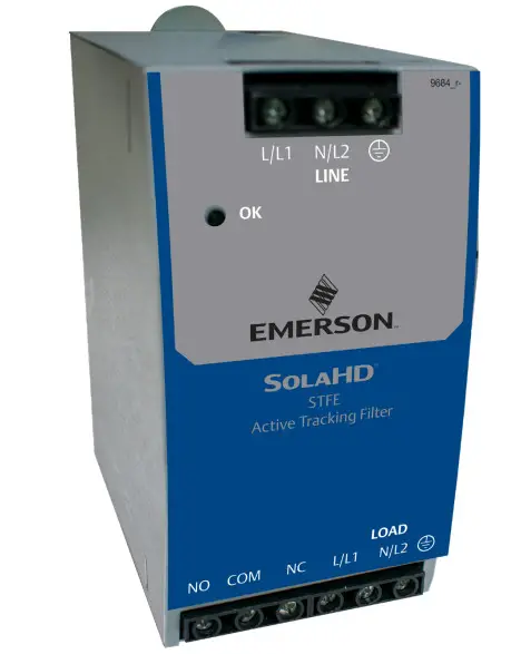
Safety Information
Important Information
Read these instructions carefully and look at the equipment to become familiar with the device before trying to install, operate, service or maintain it.
The following special messages may appear throughout this bulletin or on the equipment to warn of potential hazards or to call attention to information that clarifies or simplifies a procedure.![]() The addition of either symbol to a “Danger” or “Warning” safety label indicates that an electrical hazard exists which will result in personal injury if the instructions are not followed.
The addition of either symbol to a “Danger” or “Warning” safety label indicates that an electrical hazard exists which will result in personal injury if the instructions are not followed.![]() This is the safety alert symbol. It is used to alert you to potential personal injury hazards. Obey all safety messages that follow this symbol to avoid possible injury or death.
This is the safety alert symbol. It is used to alert you to potential personal injury hazards. Obey all safety messages that follow this symbol to avoid possible injury or death.
![]() DANGER
DANGER
DANGER indicates a hazardous situation that, if not avoided, will result in death or serious injury.![]() WARNING
WARNING
WARNING indicates a hazardous situation that, if not avoided, could result in death or serious injury.![]() CAUTION
CAUTION
CAUTION indicates a hazardous situation that, if not avoided, could result in minor or moderate injury.![]() NOTICE
NOTICE
NOTICE is used to address practices not related to physical injury. The safety alert symbol shall not be used with this signal word.
Please Note
Electrical equipment should be installed, operated, serviced, and maintained only by qualified personnel. No responsibility is assumed by Appleton Grp LLC d/b/a Appleton Group for any consequences arising out of the use of this material.
A qualified person is one who has skills and knowledge related to the construction, installation, and operation of electrical equipment and has received safety training to recognize and avoid the hazards involved.
![]() DANGER
DANGER
HAZARD OF ELECTRIC SHOCK, EXPLOSION, OR ARC FLASH
- Apply appropriate personal protective equipment (PPE) and follow safe electrical work practices. See NFPA 70E, NOM-029-STPS, or CSA Z462.
- This equipment must only be installed and serviced by qualified electrical personnel.
- Turn off all power supplying this equipment before working on or inside the equipment.
- Always use a properly rated voltage sensing device to confirm power is off.
- Replace all devices, doors, and covers before turning on the power to this equipment.
- This equipment must be effectively grounded per all applicable codes. Use an equipment-grounding conductor to connect this equipment to the power system ground.
- Do not supply more than 24VDC / 24VAC and no more than a current of 2A.
- Confirm that the Surge Protective Device voltage rating on the module or nameplate label is not less than the operating voltage.
- This equipment must be installed inside an enclosure and located so, as to prevent accidental contact with terminals during maintenance or servicing.
- Do not install in areas with excessive dust, corrosive vapors, flammable materials, or explosive atmospheres.
Failure to follow these instructions will result in death or serious injury.
![]() WARNING: This product can expose you to chemicals including DINP, which is known to the State of California to cause cancer, and DIDP which is known to the State of California to cause birth defects or other reproductive harm. For more information go to: www.P65Warnings.ca.gov.
WARNING: This product can expose you to chemicals including DINP, which is known to the State of California to cause cancer, and DIDP which is known to the State of California to cause birth defects or other reproductive harm. For more information go to: www.P65Warnings.ca.gov.
NOTICE
LOSS OF SURGE SUPPRESSION
- Make certain that Surge Protective Device is disconnected from the circuit it is protecting before conducting high-potential insulation testing.
Failure to follow these instructions can result in equipment damage.
Introduction
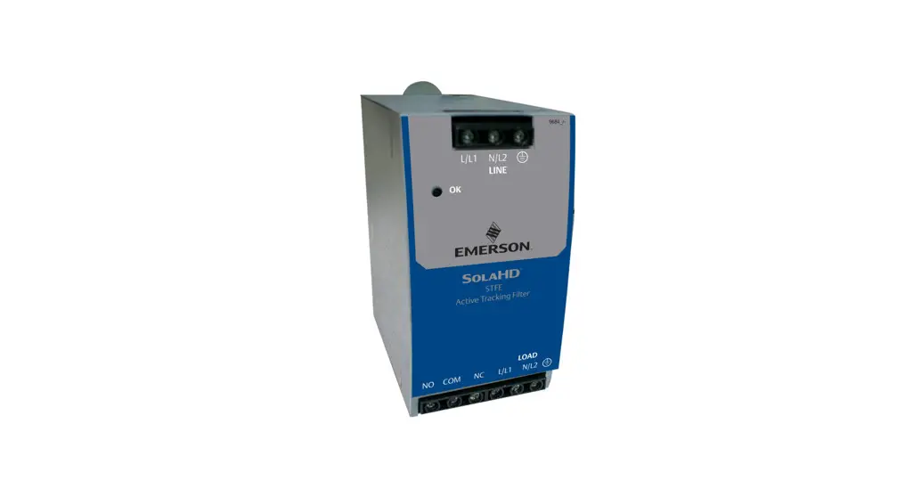
The STFE Series combines rugged, high-energy transient protection with the original Active Tracking® Filter technology to provide protection against the full spectrum of voltage transients and surges.
Proper installation is required for maximum system performance. To ensure a quality installation, the installer should read the entire manual and follow all instructions before and during the installation.
These instructions do not replace national or local electrical codes. Check applicable electrical codes to ensure compliance. Installation of the STFE Series should only be performed by qualified personnel.
Preinstallation
Location Considerations
Environment: The unit is designed for indoor operation in ambient temperatures of -40ºC (-40ºF) to +60ºC (+140ºF) with a relative humidity of 0% to 95% (noncondensing).
Supplemental Enclosures: All units provided with terminal blocks must be installed inside an enclosure and located so as to prevent accidental contact with terminals during maintenance and service.
![]() DANGER
DANGER
HAZARD OF ELECTRIC SHOCK, EXPLOSION, OR ARC FLASH
- This equipment must be installed inside an enclosure and located so, as to prevent accidental contact with terminals during maintenance or servicing.
- Do not install in areas with excessive dust, corrosive vapors, flammable materials, or explosive atmospheres.
Failure to follow these instructions will result in death or serious injury.
Electrical Connections
All electrical connections must be installed by a licensed electrician. All wiring must comply with the National Electrical Code® (NEC® ) and applicable local codes.
Voltage, Current, and Power Configurations
Maximum Current Capability: The total current draw that a unit may continuously handle is provided in the Voltage, Current, and Power Configurations table below.
NOTICE
LOSS OF SURGE SUPPRESSION
- Overloading the unit can cause permanent damage.
Failure to follow these instructions can result in equipment damage.
Nominal Voltage: The nominal operating voltage for each model is provided in the Voltage, Current and
Power Configurations table below.![]() DANGER
DANGER
HAZARD OF ELECTRIC SHOCK, EXPLOSION, OR ARC FLASH
- Confirm that the Surge Protective Device voltage rating on the module or nameplate label is not less than the operating voltage.
Failure to follow these instructions will result in death or serious injury.
Grounding
Input and output ground terminals must be connected for proper operation. Grounding is not only required for safety, but also for equipment performance. Incorrect grounding can reduce or impede the operation of the unit.
DANGER
HAZARD OF ELECTRIC SHOCK, EXPLOSION, OR ARC FLASH
- This equipment must be effectively grounded per all applicable codes. Use an equipment-grounding conductor to connect this equipment to the power system ground.
Failure to follow these instructions will result in death or serious injury.
| Voltage, Current, and Power Configurations | |||||
| Catalog Number | Load Current | Wire Size Range (AWG) | Required Torque (lb-in.) | Fuse/Circuit Breaker Ampacity | |
| Suggest | Max | ||||
| Single-Phase Models (120 VAC) | |||||
| STFE03010N | 3.0A | 14 – 10 | 4.4 lb-in. (0.50 N • m) | 3.0A | 3.75A |
| STFE05010N | 5. OA | 12 – 10 | 5.0A | 6.25A | |
| STFE10010N | 10.0 A | 14 – 12 | 4.0 lb-in. (0.45 N • m) | 10.0 A | 12.5A |
| STFE20010N | 20.0 A | 12 only | 20.0 A | 25.0 A | |
| Single-Phase Models (240 VAC) | |||||
| STFE030241 | 3.0 A | 14 – 10 | 4.4 lb-in. (0.50 N • m) | 3.0A | 3.75A |
| STFE050241 | 5.OA | 12 – 10 | 5.0A | 6.25A | |
| STFE100241 | 10.0 A | 14 – 12 | 4.0 lb-in. (0.45 N • m) | 10.0A | 12.5A |
| STFE20024L | 20.0 A | 12 only | 20.0 A | 25.0 A | |
Installation
- For units provided with a ground connection, a green (with or without one or more yellow stripes) insulated grounding conductor identical in size, insulation material, and thickness to the grounded and ungrounded conductors must be installed (ref. NEC Table 250-95) and referenced back to acceptable building ground.
- Attachment plugs, receptacles, etc. in the vicinity of the STFE Series must be of grounding type, with the grounding conductors connected to acceptable building ground.
- Terminals, lugs, and connectors used in installation must be suitable for the material of the conductors.
Conductors of dissimilar metals shall not be intermixed in a terminal or splicing.
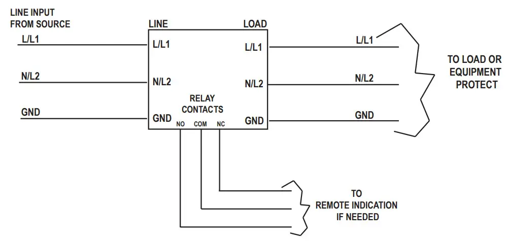
Connection Diagram
| Description | Catalog Number | |
| STFE2000 ON | STFEXXX24L | |
| Input Voltage | 120 V (0-150 VRMS) | 240 V (0-275 VRMS) |
| Line Frequency | 47-63 Hz | |
| Response Time | <0.5 ns normal mode: < 5 ns common mode | |
| Enclosure | Fully enclosed metal housing | |
| Connection!Mounting Type | DIN rail mount | |
| Status Indication | Green LED -or, Form C contact. 5 A@ 125 VAC or 5 A@ 100 VDC | |
| Weight | 1.0 lb. (0.45 kg) | |
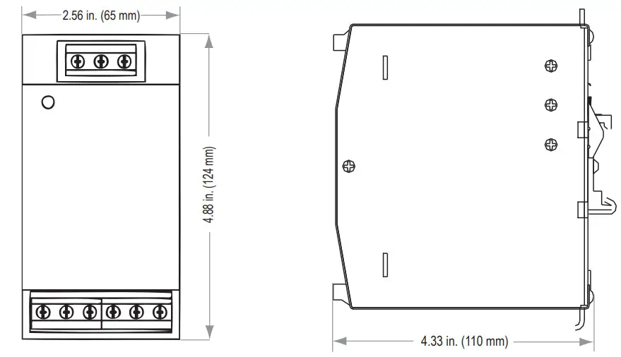
| Dimensions H x W x 0 | 4.88 x 2.56 x 4.33in. (124 x 65 x 110mm) | |
| Operating Temperature | -40°C to +50°C at full load: derate linearly to 60% at +70°C | |
| Operating Humidity | 0% to 95% Non-condensing | |
| Peak Surge Current Capability | ||
| Per Phase | 30,000 A | |
| line to Neutral | 20,000 A | |
| Line to Ground | 10,000 A | |
| Neutral to Ground | 10,000 A | |
| Load Surge Current Rating | 10 ms | 5 x Nominal |
| 1 s | 3 x Nominal | |
| 10 s | 2 x Nominal | |
| Nominal Discharge Current Rating | 3 kA | |
| Short Circuit Current Rating (SCCR) | 51th | |
| Maximum Continuous Operating Voltage (MCOV) | 150V1.-N.L-G. N-G | 320 L-L |
| Frequent Response | ||
| Normal Mode (forward-reverse) | 100 kHz to 50 MHz | -90 dB Max |
| Common Mode (forward-reverse) | 5 kHz to 50 MHz | -60 dB Max |
| Transient Reduction (IEEE C62.41). ‘All Voltage configurations are single phase. 2 wire + ground | Typical Category A Ringwave (6 kV. 200 A, 100 kHz) <60 V peak | |
| Typical Category 8 Ringwave (6 kV, 500 A, 100 kHz) < 100 V peak | ||
| Standards Certifications | cRUus: UL 1449, CSA 22.2 No. 269, UL 1283, CSA 22.2 No. 8 (recognized component), CE | |
| Warranty | 5-year limited warranty | |
Dimensional Drawings
System Design
Technical Support
Website: www.solahd.com
Technical Support E-Mail: [email protected]
Toll-Free: 1-800-377-4384
USA: 1-847-268-6651
Warranty
Please refer to the “Terms & Conditions of Sale” document.
While every precaution has been taken to ensure accuracy and completeness in this manual, Appleton Grp LLC d/b/a Appleton Group assumes no responsibility and disclaims all liability for damages resulting from the use of this information or for any errors or omissions.
The Emerson logo is a trademark and service mark of Emerson Electric Co.
Appleton Grp LLC d/b/a Appleton Group. SolaHD is a registered trademark of Appleton Grp LLC.
Active Tracking (and The Active Tracking Filter) trademarks owned by ASCO Power Technologies, L.P.
All other marks are the property of their respective owners. © 2020 Emerson Electric Co. All rights reserved.
| United States (Headquarters) Appleton Grp LLC 9377 W. Higgins Road Rosemont, IL 60018 United States T +1 800 621 1506 Australia Sales Office Bayswater, Victoria T +61 3 9721 0348 Korea Sales Office Seoul T +82 2 3483 1555 | Europe ATX SAS Espace Industriel Nord 35, rue André DurouchezCS 98017 80084 Amiens Cedex 2 France T +33 3 2254 1390 China Sales Office Shanghai T +86 21 3338 7000 | Canada EGS Electrical Group Canada Ltd. 99 Union Street Elmira ON, N3B 3L7 Canada T +1 888 765 2226 Middle East Sales Office Dammam, Saudi Arabia T +966 13 510 3702 | Asia Pacific EGS Private Ltd. Block 4008, Ang Mo KioAve 10, #04-16 TechPlace 1, Singapore 569625 T +65 6556 1100 Chile Sales Office Las Condes T +56 2928 4819 | Latin America EGS Comercializadora Mexico S de RL de CV Calle 10 N°145 Piso 3 Col. San Pedro de los Pinos Del. Álvaro Obregon Ciudad de México. 01180 T +52 55 5809 5049 India Sales Office Chennai T +91 44 3919 7300 |
![]()


