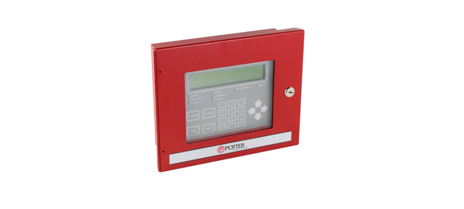
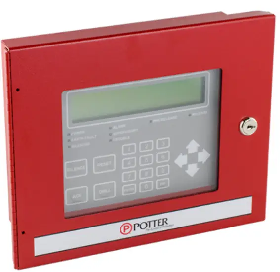
POTTER RA-6075 LCD Annunciator
Description
The RA-6075 is a LCD remote annunciator for the PFC-6075 and PFC-6030 addressable fire control panel. The RA-6075 communicates using a RS-485 connection to the main panel providing common indication of Alarms, Supervisory, Trouble and other system status and control functions. The RA-6075 features a 32 character, 16×2 LCD display with LED’s for Power, Alarm, Supervisory, Trouble, and Silenced conditions. It can be mounted on a single gang electrical box or a four square electrical box. The annunciator is enclosed in a sheet metal enclosure and has a Potter lock securing the keypad.
Features
- Standby Current 20 mA
- Alarm Current 25 mA
- Operating Temperature 0°C-49°C (32°F-120°F) 10%-93% @ 30°C (86°F) non-condensing humidity
- Maximum Wire Length 6500 FT
- Maximum Annunciators 31
- Dimensions (WxHxD) 8” x 6-1/4” x 1-5/8” (Cabinet)
- Wire Gauge 14 AWG-22 AWG
- Display 2 lines x 16 characters
Installation
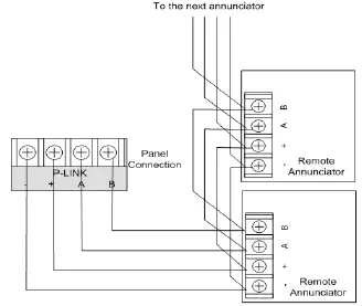
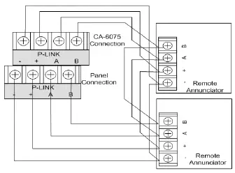
The RA-6075 is connected to the PFC-6075 using a four wire RS-485 connection. The connection is power limited and supervised. Up to thirty-one (31) RA-6075 LCD annunciators can be connected using Class B or Class A wiring. Class A wiring requires an optional Class A Expander.
NOTICE
Install in accordance with compatible fire alarm panel
DIMENSIONS
RA-6075 Class B Wiring Example
RA-6075 Class A Wiring Example
Address Settings
The RA-6075 address is set by dip switch S1 located on the back of the RA-6075. The address must be set in the range of 1 to 31 to be recognized by the control panel.
RA-6075 Class A (back panel view)
Dip Switch Settings
Refer to the table below for dip switch settings per Annunciator Address
| Annunciator Address | Dip Switch Settings | Annunciator Address | Dip Switch Settings | |||||||||
| SW-1 | SW-2 | SW-3 | SW-4 | SW-5 | SW-1 | SW-2 | SW-3 | SW-4 | SW-5 | |||
| 1 | On | Off | Off | Off | Off | 17 | On | Off | Off | Off | On | |
| 2 | Off | On | Off | Off | Off | 18 | Off | On | Off | Off | On | |
| 3 | On | On | Off | Off | Off | 19 | On | On | Off | Off | On | |
| 4 | Off | Off | On | Off | Off | 20 | Off | Off | On | Off | On | |
| 5 | On | Off | On | Off | Off | 21 | On | Off | On | Off | On | |
| 6 | Off | On | On | Off | Off | 22 | Off | On | On | Off | On | |
| 7 | On | On | On | Off | Off | 23 | On | On | On | Off | On | |
| 8 | Off | Off | Off | On | Off | 24 | Off | Off | Off | On | On | |
| 9 | On | Off | Off | On | Off | 25 | On | Off | Off | On | On | |
| 10 | Off | On | Off | On | Off | 26 | Off | On | Off | On | On | |
| 11 | On | On | Off | On | Off | 27 | On | On | Off | On | On | |
| 12 | Off | Off | On | On | Off | 28 | Off | Off | On | On | On | |
| 13 | On | Off | On | On | Off | 29 | On | Off | On | On | On | |
| 14 | Off | On | On | On | Off | 30 | Off | On | On | On | On | |
| 15 | On | On | On | On | Off | 31 | On | On | On | On | On | |
| 16 | Off | Off | Off | Off | On | |||||||
- Potter Electric Signal Company, LLC
- St. Louis, MO
- Cust Service: 866-956-1211
- Tech Support: 866-240-1870
- Canada: 888-882-1833
- www.pottersignal.com


