
Power Shield PSATS3K Automatic Transfer Switch User Guide
Introduction
The PowerShield® ATS is designed to accept two independent power inlets (primary and secondary) to supply power to the load from either power source. Should primary power source fail, the secondary will automatically back up the connected equipment without any interruption. The transfer time from one line to another is seamless to the connected equipment. After switching to a secondary power source, the ATS can also switch power back to the primary input when power to the primary input is restored.
Package contents:
- ATS module
- User manual
- CDROM – ATS Monitoring software
- Mounting brackets
- 2 x power cord – 15 Amp Australian 3-pin plug to 15Amp IEC C19 socket
- 1 x power cord – 15Amp IEC C19 socket to IEC C20 plug
- 2 x power cord – 10Amp IEC C13 socket to IEC C14 plug
- 1 x USB cable
Product Overview
Front View: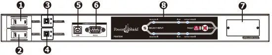
- Power switch for input source A
- Power switch for input source B
- Circuit breaker for output 2
- Circuit breaker for output 3
- USB communication port
- RS-232 communication port
- Communication slot
- Operation indicators (please refer to section 4 for the details)
Back View: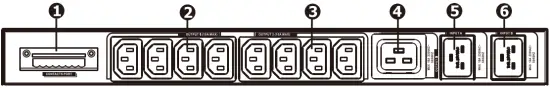
- Contact port (please refer to section 7 for the details)
- Output receptacles “Output 3” (IEC 10A)
- Output receptacles “Output 2” (IEC 10A)
- Output receptacle “Output 1” (IEC 16A)
- Input source A connector
- Input source B connector
Important Safety Warnings
Before using the unit please read all instructions and cautionary markings on the unit, this manual and the batteries.
WARNING!! The ATS must be connected to earth when in use.
In line with current regulations, only use the cables that have been supplied with the machine. The power supply socket must be easily accessible to the operator.
WARNING!! The ATS has been designed exclusively to operate indoors. It is essential to install it in areas where no inflammable liquids or gases, or other harmful or noxious substances, have been stored.
ATTENTION!! A soft damp cloth may be used to clean the outside of the machine (always with the system disconnected from the mains power supply and load).
Do not use any type of solvent as this may damage the external finish of the machine.
ATTENTION!! The ATS has been designed exclusively for professional use.
NOTE: These instructions may be modified by the wiring regulations in force in the country where the ATS is purchased.
Operational Indicator & Status

- Preferred Source Selector
- Priority setting LEDs
- Power source status LEDs
- Output source LEDs
- Fault indicator
- Alarm mute button
LED Indicators and Alarms
| Indication type | LED description | LED status | Condition | Alarm |
| Priority setting LEDs | Source A (2) | ON | Source A is Preferred | OFF |
| Source B (2) | OFF | |||
| Source A (2) | OFF | Source B is Preferred | OFF | |
| Source B (2) | ON | |||
| Power source status | Status of source A (3) | OFF | Inlet A has no power input | OFF |
| ON | Inlet A has power input, and power is OK | OFF | ||
| Flashing | Inlet A has power input, but power is out of SPEC | OFF | ||
| Status of source B (3) | OFF | Inlet B has no power input | OFF | |
| ON | Inlet B has power, and power is OK | OFF | ||
| Flashing | Inlet B has power input, but power is out of SPEC | OFF | ||
| Output status | Output from source A (4) | ON | Output on Source A | OFF |
| Output from source B (4) | OFF | |||
| Output from source A (4) | OFF | Output on Source B | OFF | |
| Output from source B (4) | ON | |||
| Output from source A (4) | OFF | NO OUTPUT |
OFF | |
| Output from source B (4) | OFF | |||
| Alarm | Fault (5) | OFF | No Alarms present | OFF |
| ON | Alarm present | Continuously |
Installation
NOTE: Before installation, please inspect the unit. Be sure that nothing inside the package is damaged.
Mounting the Unit
The unit can be mounted in a standard 19″ rack using the PowerShield optional Rail Kit. Fasten the mounting brackets to the unit using the screws provided.
Power Shield Rail Kit mounting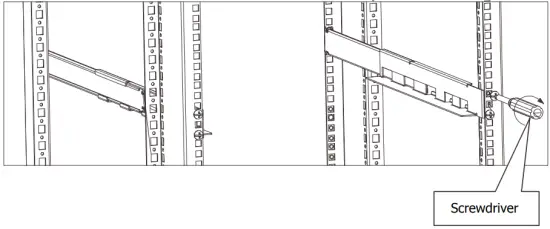

NOTE: If the ambient temperature exceeds 40 °C, ventilation is required
Connecting the Unit
Connect the ATS input plugs “input source A connector” and “input source B connector” to the two independent power sources or UPSs using either the SCHUCKO-IEC or IEC-IEC 16A cables supplied.
Plug the load into the output 10A (“Output 1 and 2”) or 16A (“Output 3”) sockets depending on requirements.
Operation
Power On/Off
Turn the input power switch to the “ON” position. The output will then be supplied by the source set as selected.
Setting the Preferred Power Source
It is possible to set the power source preference by pressing “source preference selector”. The default power source is “Source A”.
| Function | Description | Default | Possible configuration |
| Source preference selector | Input Selection that normally supplies the load | Source A |
|
Communication Port
The ATS is supplied with the following communication ports:
- Serial port is available with RS232 com. port and USB com. port on the front panel.
NOTE: the use of one port automatically excludes the other. - Contact port on the rear panel.
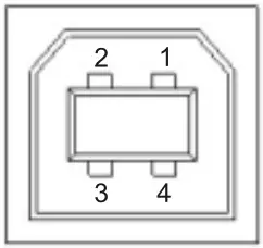
Serial Ports: RS-232 & USB connectors
- RS-232 connector

PIN # NAME TYPE SIGNAL 1 2 TX OUT Serial line TX 3 RX IN Serial line RX 4 5 GND POWER 6 +12V POWER 7 8 9 - USB connector

PIN # SIGNAL 1 VBUS 2 D- 3 D+ 4 GND NOTE: The utilization of the communication port is optional and it is not necessary for the normal function of the ATS.

Contact Outputs
The contact outputs consist of six (6) pins numbered from left to right (see fig. 1), which can be connected to an external monitoring system (such as a BMS) in order to monitor the operational status of the ATS.
The external equipment must be within the rating of the contacts
Fig. 1: Contacts Connector
The Contact Connector provides the following connections:
- Pin 1: Common contact.
- Pin 2: “Source B” active contact – pins 1 and 2 closed = output supplied by “Source B”
- Pin 3: “Source A” active contact – pins 1 and 3 closed = output supplied by “Source A”
- Pin 4: “Source A” status OK contact – pins 1 and 4 closed = “Source A” is present and normal
- Pin 5: “Source B” status OK contact – pins 1 and 5 closed = “Source B” is present and normal
- Pin 6: Status OK contact – pins 1 and 6 closed = ATS operation normal
The following diagram shows the contact configuration
Fig. 2: Contact Connections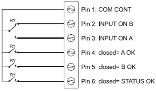
ATTENTION: Contact Connector pins are rated at a current of 8A and voltage of 250Vac.
Trouble Shooting
| Problem | Possible Cause | Solution |
| The ATS with the mains voltage present, does not turn on. (The LEDs does not flash and no alarm sounds.) | Input plugs not connected | Connect the mains to the input plugs as indicated in the installation section. |
| Input switch in “OFF” position | Turn the input switches “ON” | |
| Input power failure | Check that the mains voltage is present or check if the UPS supplying the ATS is on. | |
| Upstream Fuse or CB disconnected | Reset the CB or Fuse Warning: check that there is no overload or short- circuit at the output of the UPS. | |
| The load is not powered. | Output sockets not connected | Connect the load to the output sockets |
| 10A Internal thermal protection device has tripped | The Internal protection will operate in the event of a short circuit or overload on one of the 10A output sockets. The thermal protection can be reset by pushing the button which will result in the power being reconnected to the load. Therefore prior to attempting a reset of the thermal protection, check the rating of the connected loads and determine if there is any overload. Then once reset, reconnect each load one at a time to ensure no problems exists. | |
| No display or display provides incorrect information. | There is a power supply problem in the display. | Shut down the ATS completely and wait for a few seconds. Switch the ATS on again, if the problem persists, contact the nearest technical support centre. |
| The display is off but the load is powered. | There is a power supply problem in the display. | Contact the nearest technical support centre. |
If there is any abnormal situation not listed above, please call PowerShield Service immediately for professional Technical Support
Technical Specifications
| MODEL | PSATS 3K |
| INPUT | |
| Input Voltage | 220/230/240 VAC |
| Input Voltage Range | 180 – 258 VAC |
| Input Frequency | 50 Hz/60 Hz |
| Maximum Input Current | 16 A |
| OUTPUT | |
| Output Voltage | 220/230/240 VAC |
| Maximum Output Current | 10 A for IEC-C13 outlets 16 A for IEC-C19 outlet |
| CONNECTION | |
| Input | 2 x IEC-C20 inlets |
| Output | 8 x IEC-C13 1 x IEC-C19 |
| Communication | USB, RS-232, AS400 or SNMP option |
| TRANSFER TIME | 9-12ms (Typical) |
| PHYSICAL | |
| Dimensions, D X W X H (mm) | 330 X 483 X 44 |
| Net Weight (kgs) | 5.0 |
| ENVIRONMENT | |
| Operating Temperature | 0-95 % RH @ -5°C- 45°C (non-condensing) |
Appendix
Input Voltage and Frequency Thresholds
| FUNCTION | DESCRIPTION | DEFAULT SETTING |
| Input voltage range for Source A | If Source A is the active source, when the input voltage is outside this range, the ATS will automatically switch to Source B. | 180V – 265V |
| Return voltage point for Source A | When input voltage of Source A is back to normal, the ATS will switch back to Source A. (Setting is Source A as Preferred Power source) | Low: 190V High: 258V |
| Input voltage range for Source B | If Source B is the active power source, when the input voltage of source B is outside this range, the ATS will automatically switch to Source A. | 180V – 265V |
| Return voltage point for Source B | When input voltage of Source B is back to normal, the ATS will switch back to Source B. (Setting is Source B as Preferred power source) | Low: 190V High : 258V |
| Input frequency for Source A | If Source A is the active source, when the input frequency of source A is outside this range, the ATS will automatically switch to Source B. | 45Hz – 55Hz |
| Input frequency for Source B | If Source B is the active source, when the input frequency of source B is outside this range, the ATS will automatically switch to Source A. | 45Hz – 55Hz |
Default factory settings: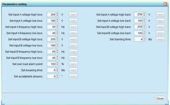
WARRANTY
VERY IMPORTANT: Warranty Registration
In order to validate product warranty, it is essential that you register your product on line.
Please Visit PowerShield on line product warranty web page to register www.powershield.com.au/product-registration.php
NOTE: For information about our Warranty Terms and Conditions, please visit our web site. www.powershield.com.au under Support.
This user manual contains instructions relating to safety, installation, operation, maintenance and warranty of this product.
Please keep this manual in a safe place for future references
WARRANTY SERVICE PROCESS:
- Review the problems discussed in the troubleshoot section of this manual to eliminate common problems.
- Verify that no input/output circuit breaker have tripped. A tripped circuit breaker is the most common problem.
- If the problem still persists, please call 1300-305-393 for technical support or fill in the RMA application form in PowerShield web page www.powershield.com.au/rmaform/
The following details are needed for warranty claims.
- Model number
- Serial number
- The date of purchase