Tigo TSS-50-US 50A EI Automatic Transfer Switch
General Information
The Energy Intelligence (EI) ATS Installation & Operations
Manual provides detailed instructions for the installation and operation of the EI Automatic Transfer Switch (ATS). Failure to follow the contents of this manual may result in damage that is not covered by the warranty.
Package Contents
- TSS-50-US ATS – 1
- Quick Start Guide – 1
- Sleeve anchors – 3
- Mounting screws – 2
- O-type terminal – 3
- Wire ferrules – 9
- Keys – 2
- Mounting bracket – 1
Required Tools
| Item | Quantity |
|---|---|
| Wire cutter/crimp tool | |
| Screwdriver | |
| Rubber mallet/hammer | |
| Drill | |
| Level |
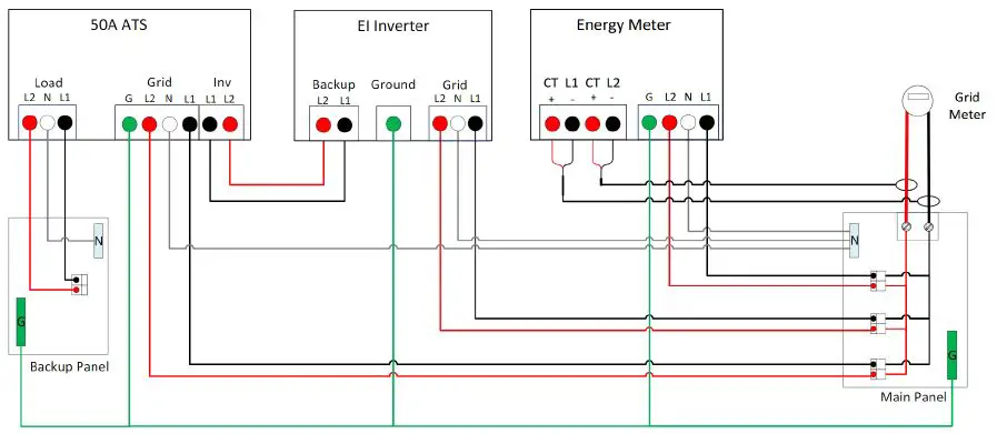
AC Wiring Diagram
The EI ATS is connected to the backup panel, inverter, and grid
using the AC wiring diagram provided.

Installation
Mounting
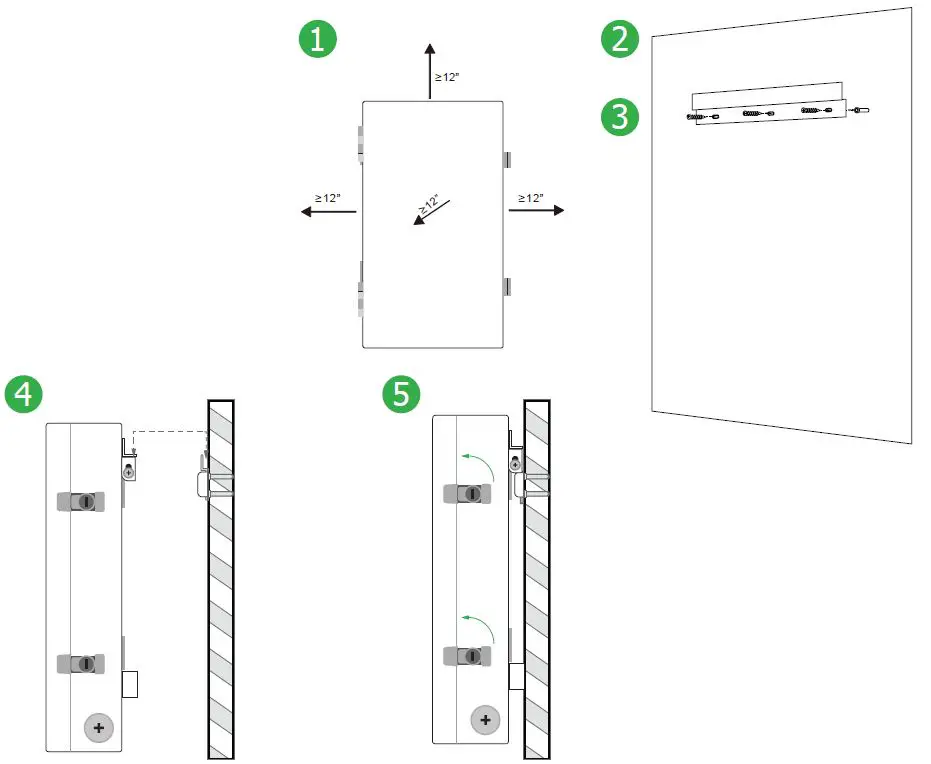
When mounting the EI ATS, reserve at least 12 inches on all sides. Follow the steps below:
- Use a level and the mounting bracket to mark the mounting holes on the wall.
- Drill out the mounting holes to a depth of 1.6 inches (40mm).
- Place a sleeve anchor in each hole and tap with a rubber mallet/hammer.
- Place the mounting bracket aligned with the anchors exposed through the screw holes and use the mounting screws to attach to the wall.
- Confirm that the bracket is level and screws are tight, then lift the EI ATS onto the mounting bracket.

The EI ATS overview shows the different components of the system.
Electrical Connections
Wire Schedule/Preparation
Follow the steps below to prepare the AC and ground conductors for connection:
- Use wire cutters to strip 15mm of insulation from one side of each AC conductor (L1, L2, N) and crimp a wire ferrule to the end of each conductor.
- If using insulated conductors, strip 7mm of insulation from one side of each ground conductor and crimp an O-type terminal to the end.
Conductor Schedule
| Conductor | Quantity | Type | Size |
|---|---|---|---|
| Grid | 3 | L1, N, L2 | 8-6AWG |
| Inverter | 2 | L1, L2 | 8-6AWG |
| Backup Load | 3 | L1, N, L2 | 8-6AWG |
| Load EGC | 1 | 8-6AWG | |
| Grid EGC | 1 | 8-6AWG | |
| Inv backup EGC | 1 | 8-6AWG |
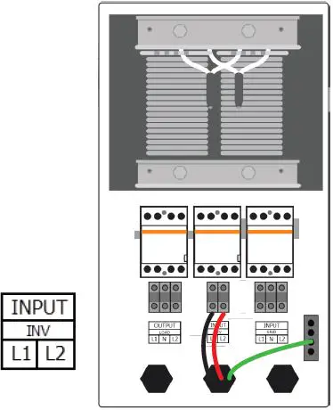
Inverter Connections
Connect the inverter to the EI ATS as specified in the AC wiring diagram.
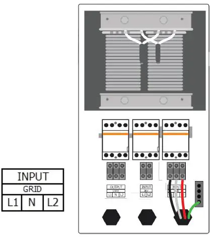
Grid Connections
Connect the grid to the EI ATS as specified in the AC wiring diagram.
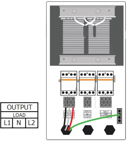
Backup Connections
Connect the backup panel to the EI ATS as specified in the AC wiring diagram.
Pre-power Checklist
Before powering on the EI ATS, complete the following checklist:
| Check Item | Acceptance Criteria |
|---|---|
| ATS installation | The ATS is installed correctly, securely, and reliably. Conduit/cables and conductors are routed properly, and as requested by the customer. |
| Cable connections | The AC output conductors, DC input conductors, and communications cables are labeled and connected correctly and securely. Cable ties are secured evenly with no sharp protrusions. Ground conductors are connected correctly, securely, and reliably. |
General Information
ATTENTION – READ FIRST
- This document is for quick guidance only. For details, please refer to the Energy Intelligence (EI) ATS Installation & Operations Manual.
- Damage caused by failure to follow the contents of the EI ATS Installation & Operations Manual is not covered by the warranty.
- Before installing the system, check that the package contents are intact and complete against the packing list. If any damage is found or any component is missing, contact your dealer.
Package Contents
| Item | Quantity | |
| TSS-50-US ATS | 1 | Box |
| Quick Start Guide | 1 | Box |
| Sleeve anchors | 3 | Bag |
| Mounting screws | 2 | Bag |
| O-type terminal | 3 | Bag |
| Wire ferrules | 9 | Bag |
| Keys | 2 | Bag |
| Mounting bracket | 1 | Box |
Required Tools
| Item |
| Wire cutter/crimp tool |
| Screwdriver |
| Rubber mallet/hammer |
| Drill |
| Level |
CAUTION – Use tools with insulated handles. Always wear appropriate PPE.
wiring diagram
EI ATS Overview
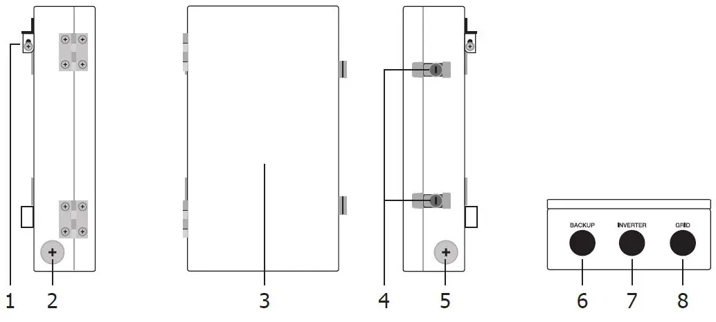
- Mounting bracket
- 1 1/4″ knockout
- Front door
- Door locks
- 1 1/4″ knockout
- 1” backup load knockout
- 1” inverter knockout
- 1” grid knockout
Product Installation
Mounting
CAUTION – Use appropriate hardware for the mounting surface
- Reserve at least 12” on all sides of the ATS.
- Use a level and the mounting bracket (1) to mark the mounting holes. Drill out mounting holes to 1.6” (40mm) depth.
- Place the sleeve anchor in each hole, tap with the mallet/hammer. Place mounting bracket aligned with the anchors exposed through the screw holes and use the 3 mounting screws to attach to the wall.
- Confirm bracket is level and screws are tight then lift ATS on to the mounting bracket.
- To open the door, insert key into top lock, turn 90° counterclockwise, then repeat on bottom lock.
Electrical connections
CAUTION – Check that all Disconnect switches are OFF before wiring. For personal safety, do not operate with electricity and always wear appropriate PPE.
Wire schedule/preparation
- To prepare the AC conductors (L1, L2, N), use the wire cutters to strip 15mm of insulation from one side of the conductor and crimp the wire ferrule to the end of the conductor.
- To prepare the ground conductors, strip 7mm of insulation (if using insulated conductors) from one side of the conductor and crimp the O-type terminal to the end.
| Conductor Schedule | |||
| Conductor | Quantity | Type | Size |
| Grid | 3 | Min. 90°C rated, insulated, copper, solid or stranded (not fine stranded) | L1, N, L2: 8-6AWG |
| Inv Backup | 2 | L1, L2: 8-6AWG | |
| Load | 3 | L1, N, L2: 8-6AWG | |
| Load EGC | 1 | Min. 90°C rated, insulated or bare, copper, solid or stranded (not fine stranded) | EGC: 8-6AWG |
| Grid EGC | 1 | ||
| Inv backup EGC | 1 | ||
Inverter connections
Note – Refer to section 3.4 Backup output connections in the EI Inverter quick start guide for the connection of these conductors in the inverter.
- Loosen screws in positions L1 and L2 at the INPUT INV terminals.
- Insert the L1 and L2 inverter backup conductors into the INPUT INV L1 and L2 terminals.
- Tighten screws to 2.5Nm.
- Secure the inverter EGC to the ground busbar.
Grid connections
CAUTION – Two control lines are terminated to positions 3 and 5 of the contactor. These are necessary for the operation of the ATS. DO NOT REMOVE.
Note – The opposite end of the GRID conductors is fed from the main service panel by a 50A circuit breaker.
- Loosen screws in positions L1, N, and L2 at the INPUT GRID terminals.
- Insert the L1, N, and L2 grid conductors into the INPUT GRID L1, N, and L2 terminals.
- Tighten screws to 2.5Nm.
- Secure the GRID EGC to the ground busbar.
Backup connections
Note – The opposite end of the BACKUP load conductors feed the subpanel dedicated to backup loads.
- Loosen screws in positions L1, N, and L2 at the OUTPUT LOAD terminals.
- Insert the L1, N, and L2 backup load conductors into the OUTPUT LOAD L1, N, and L2 terminals.
- Tighten screws to 2.5Nm.
- Secure the LOAD EGC to the ground busbar.
Pre-power checklist
| Check Item | Acceptance Criteria |
| ATS installation | The ATS is installed correctly, securely and reliably. |
| Conduit/Cable layout | Conduit/cables and conductors are routed properly, and as requested by the customer. |
| Cable connections | The AC output conductors, DC input conductors, and communications cables are labeled and connected correctly and securely. |
| Cable ties | Cable ties are secured evenly with no sharp protrusions. |
| Grounding | Ground conductors are connected correctly, securely and reliably. |
| Conduit connections | All conduit attachments are sealed and bonded, when necessary. |
| Unused conduit openings | Any unused conduit openings are fitted with waterproof caps or left unopened. |
| Disconnect switches | All external disconnect switches connecting to the ATS are in the OFF position. |
| Wirebox cleanliness | The wirebox is left clean and tidy. |
| Installation environment | An appropriate installation space had been chosen and the environment is left clean and accessible. |
Commissioning
CAUTION – For personal safety always wear appropriate PPE. After completing the Pre-power checklist, close the cover.
If the battery, inverter, backup load panel installations are already complete, the system may now be turned on for operation. Follow the EI Inverter’s Commissioning instructions (Section 6) to commission the system.
Keep the instruction manual and keys nearby.
Troubleshooting
| Issue | Check |
| In grid-on operation the ATS does not switch over when there is loss of grid. | 1. Turn OFF the EI Inverter and the grid. 2. Open the ATS door and check the grid and INV conductors are properly connected to the correct terminals. 3. If issues persist, please contact Tigo Customer Service team. |
| Backup load panel has no power. | 1. Turn OFF the EI Inverter and the grid. 2. Open the ATS door and check the control line, the INV and BACKUP conductors are properly connected to the correct terminals. 3. If issues persist, please contact Tigo Customer Service team. |
7. Your Customer Service Contact
Tigo Energy, Inc.
655 Campbell Technology Pkwy Campbell, CA 95008
T: +1 408 402 0802
https://support.tigoenergy.com/
©20230425 Tigo Energy, Inc. 002-00086-00 1.2


 User Manual")