 TRADITIONELLE DEUTSCHE QUALITAT
Manual
Please, read this manual carefully before use!
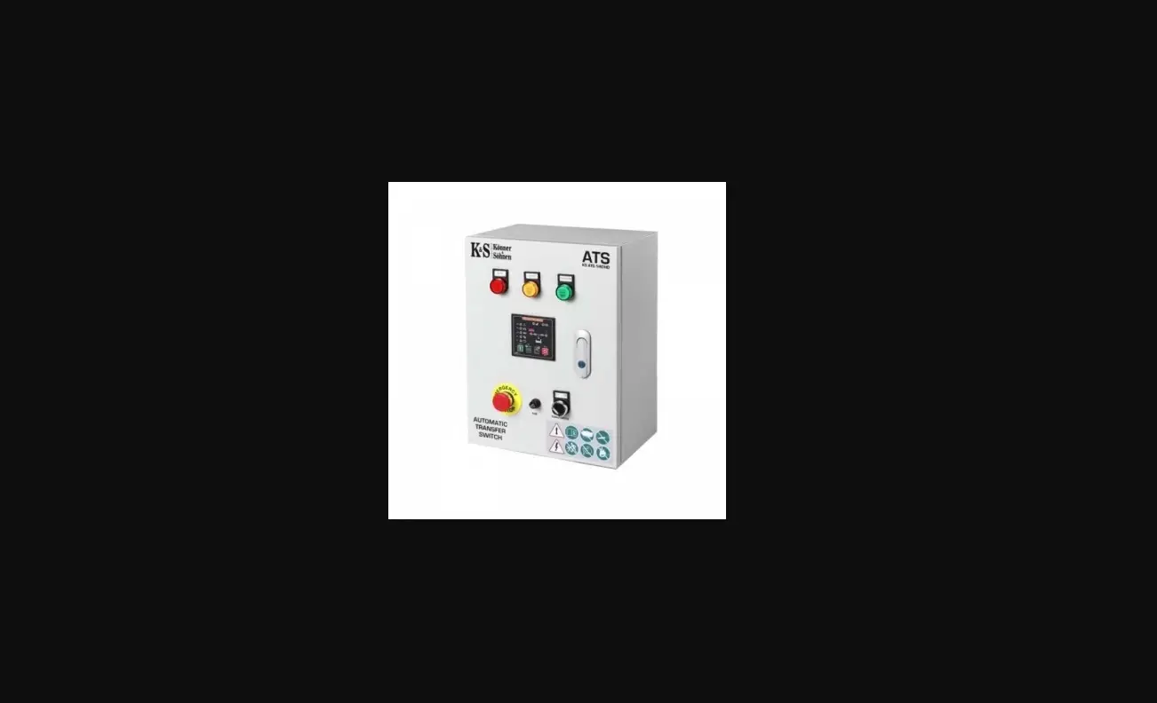
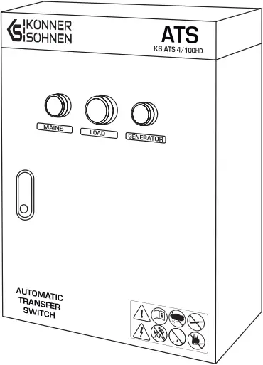
AUTOMATIC TRANSFER SWITCH (ATS)
KS ATS 4/100HD
KS ATS 4/100HD-O
PREFACE 
Thank you for your purchase of ATS from Könner & Söhnen®. This manual contains safety instructions, a description of the use and commissioning of the ATS and procedures for its maintenance.
The manufacturer reserves the right to make changes in the product design, configuration and construction. The images and drawings in this manual are for reference only and may differ from the actual components and inscriptions on the products.
Contact information that you are free to use in case of any problems can be found at the end of this manual. All information in this manual is correct to the best of our knowledge and belief at the date of its publication. The current list of service centers can be found on the official importer’s website: www.koenner-soehnen.com
![]() PLEASE NOTE!
PLEASE NOTE! ![]()
In order to ensure equipment integrity and avoid possible injuries, we recommend that you read this manual before operating the product.
ATS UNIT USE AND SAFETY PRECAUTIONS 1
WORK AREA
Do not use the product near flammable gases, liquids or dust. Keep the work area clean and well lit to avoid injuries. Keep unauthorized persons, children and animals away from the running product.
ELECTRICAL SAFETY
The product is energized. Observe safety precautions to avoid electric shock. Avoid operating the product in high-humidity environments. Do not allow moisture to enter the product, as this increases the risk of electric shock. Avoid direct contact with grounded surfaces (pipes, radiators, etc.). Be careful when working with the power cord. Replace it immediately in case of damage, as damaged power cord increases the risk of electric shock. All product connections must be carried out by a certified electrician in accordance with all electrical codes and regulations. Do not operate the product with your feet in the water, on wet or damp soil. Do not touch live parts of the product. Keep all electrical equipment dry and clean. Replace damaged or worn wiring. Worn, damaged, or rusted terminals must be replaced as well.
PERSONAL SAFETY
Do not operate the product when you are tired or under the influence of potent drugs, alcohol or medication. During operation, inattention can cause serious injury. Make sure there are no foreign objects on the product when it is turned on. Do not overload the product; use it for its intended purpose only.
![]() PLEASE NOTE!
PLEASE NOTE! ![]()
The total power of power consumers connected to the ATS system must not exceed the maximum permissible power for this ATS unit model.
![]() WARNING!
WARNING! ![]()
This material is for informational purposes only and is not an instruction how to install or connect equipment to the network. In practice, there are different options for supplying electricity and different rules for its connection. The decision on how to properly connect the equipment in each individual case must be made by a certified electrician who performs the installation and electrical connection of the equipment. The manufacturer is not responsible for improper connection of equipment, and is not responsible for possible material and physical damage that may occur as a result of improper installation, connection or operation of equipment.
SPECIFICATIONS 2
Model | KS ATS 4/100HD | KS ATS 4/100HD-O |
| Consumption | 18W | 18W |
| Operating voltage | 230 V/400 V | 230 V/400 V |
| Power 230 V, kVA, cosPhi 1.0 | 23 кW | 23 кW |
| Current (max) 230 V | 100 A | 100 A |
| Power 400 V, kVA, cosPhi 0.8 | 55 кW | 55 кW |
| Current (max) 400 V | 100A | 100A |
| Working environment | -20-45 °С humidity: ≤ 50% | |
| Storage environment | -30-70 °С humidity: ≤ 50% | |
| IP protection class | IP44 | |
| Insulation class | AC1.0KV/1min 1mA | |
| Net dimensions (LxWxH), mm | 500x300x600 | 515x415x150 |
| Net weight, kg | 22.3 | 5 |
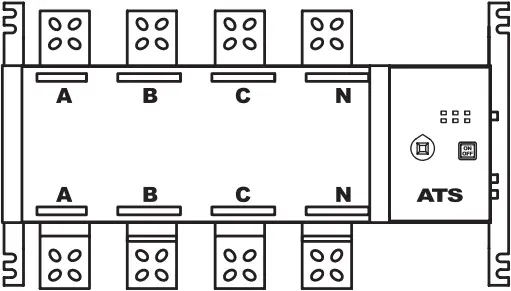
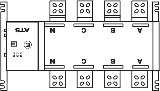
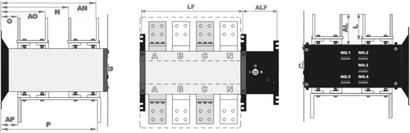
GENERAL VIEW OF THE ATS UNITS 3
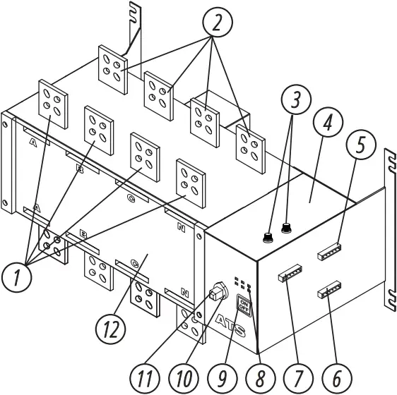
1. Main power input bars: used for fixed the main power саblе or busbar
2. Standby power input bars: used for fixed the main power саblе or busbar
3. Working power fuses
4. Electronic control unit of transfer switch:
including main control circuit board and driven motor.
5. Terminal #2: Transferring control signal intput (passive output)
6. Terminal #3: Position feedback control signal output 1 (active output for M type and passive output for)
7. Terminal #1: Electronic control unit power supply input
8. LED indicators
9. Electric/emergency manual mode selection button
10. Switch position status indicator
11. Manual emergency handle interface: used to tum the switch manually to switchover the power supply at an emergency situation.
12. Transferring switch bоdу: the standard type is equipped with upper incoming lines and lower busbar outgoing lines.
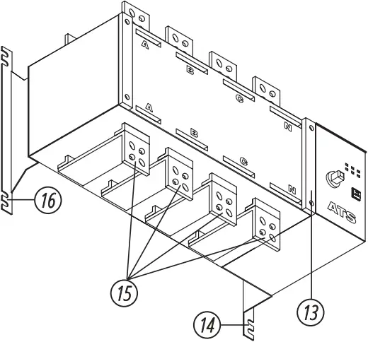
13. Safety guard plate installation holes, used for fixing the safety guard plate
14. Right installation bracket: matched with the lefl installation bracket and used for fixing switches
15. Load power output bars: used for fixing installation the load cables or busbars.
16. Lefl installation bracket: matched with the right installation bracket and used for fixing switches
![]() IMPORTANT!
IMPORTANT! ![]()
Manufacturer reserves the right to make changes and/or improvements in design, components set and technical attributes without notice and without incurring obligation. The pictures in this manual are schematical and may not match the parameters of original product.
CONTROLLER MAIN TECHNICAL PARAMETERS 4
Conventional thermal current ith | 100A |
| Rated insulation voltage of copper bar, Ui | 750V |
| Rated impulse withstand voltage, Uimp | 8 kV |
| Rated operating voltage of copper bar, Ue | AC440V |
| Use category | АС-ЗА |
| Rated operating current of copper bar, Іе | 100 |
| Rated making capacity | 10Іе (10 times the rated current) |
| Rated breaking capacity | 8le (8 times the rated current) |
| Rated limit short-circuit current | 100 kА |
| Rated short time withstand current | 9 kА |
| Transferring time І – II or II – І | 0.45 s |
| Rated operating voltage of the control power supply, Us | Standard product: AC220V, |
| Start | 300W |
| Normal | 55W |
| Net weight (4-роІе), kg | 3.5 |
SCHEMATIC DIAGRAM OF CORRECT INSTALLATION METHOD 5
BEST RIGHT
(front installation) (back installation)
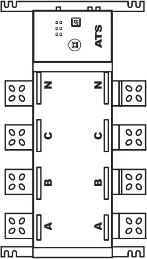
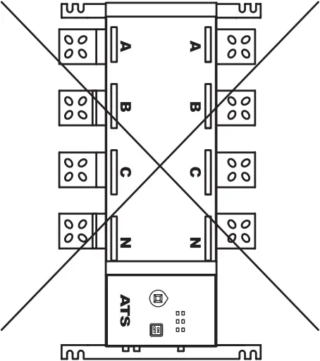
RIGHT WRONG
(vertical installation) (inverted installation)
ENVIRONMENTAL REQUIREMENTS FOR USE 6
Name | Requirements |
| Operating temperature | -20 То +45°С, the average value for 24 hours shall not exceed +35°С; |
| Operating humidity | The average humidity under the +40°С conditions shall not exceed 50% without condensation; |
| Altitude | Lower than 2000 meters and, if higher than 2000 meters, reduce its rated value for use: |
| Vibration and gas | There shall bе no strong vibration or shock апd nо harmful gases to corrode the metals and to damage the insulation within the environment of its use; |
| Surrounding material | There shall bе nо serious dust, conductive particles or explosive hazardous substances |
| Class of pollution | Class III |
| ІР rating | IP20 |
| Storage requirements | То bе stored under -З0 То 70°С and in а dry, non-corrosive and saline environment and the longest period of storage shall bе 1 year |
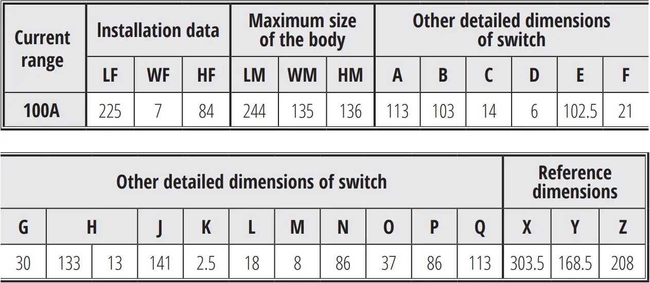
DIMENSIONS 7
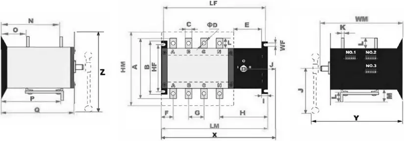
![]() NOTE!
NOTE! ![]()
Х, У and Z аrе the maximum width, depth and height of the switch assembled with а manual emergency handle.
Depending оn the angle of the handle when installing ог the difference of positions of the slider moving, the corresponding dimensions will Ье smaller than the data listed in the table above, which аге listed for reference only.
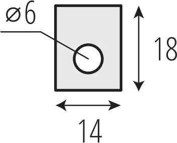
INPUT AND OUTPUT СОРРЕR BАR DIMENSIONS CHART
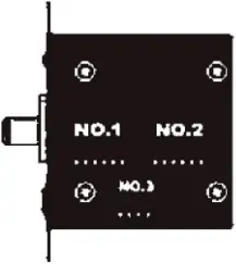
TERMINAL FUNCTIONS INTRODUCTION 8
Terminal Serial № | Access point serial № | Function | Notes |
| Terminal №1 | 101, 106 | Power supply neutral wire for feedback and live wire output | Active output, 1 А |
102, 103 | №1 operating power supply live wire and neutral wire input | >5А АС 230V | |
| 104, 105 | №2 operating power supply live wire and neutral wire input | >5А АС 230V | |
Terminal №2 | 201, 206 | Passive control when disconnected and active control when closed | See SКТ Туре Ргіnсірlе diagram for details |
| 202 | External passive control signal input common terminal | Passive control signals | |
203 | Line І is switched оn, when closed with 202 | ||
| 204 | Line 0 is switched оn, when closed with 202 | ||
205 | Line IІ is switched оn, when closed with 202 | ||
| Terminal №3 | 301, 306 | Not used, directly connected internally | 20А-250А Unassembled |
302 | Passive position feedback signal output common terminal | М type is active output, the other types are passive output, see the principle diagram for details 1А АС 220V 400A and above assembly | |
303 | Closed with 302, when Line І is switched оn | ||
| 304 | Closed with 302, | ||
305 | Closed with 302, |
TERMINAL LOCATION DRAWING
Х type 100А
INSTRUCTIONS FOR USE OF LED INDICATORS 9
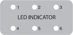
№1 | №2 |
| Line І control power supply is powered-on. (Тhere is АС 220V between the access points 102 and 103 of No.1 terminal) | Line І control power supply fuse is normal. |
№3 | №4 | №5 | №6 |
| Line І control relay is normal (the relay is mounted оп the internal circuit board and No.3 light is used for this function, оnІу when No.4 light is not Ііt up). | Line II control power supply is powered-on (Тhere is AC 230V between the access points 104 and 105). | Line II control power supply fuse is normal. | 125А-250А switch, key lock or button is in the AUTO position (the key lock оr the button is mounted оn the front side of the switch). 400A-3200A switch and Line II control rеІау аrе normal (the relay is mounted оn the internal circuit board). |
INSTRUCTIONS FOR RAPID APPLICATION ОF LED INDICATORS:
А. No. 1 and No. 4 indicator lights are lit up, which stands for that the control power supply оІ the lines І and II are powered оn.
В. No. 2 and No. 5 indicator lights are Ііt up, which stands for that the fuses of the control power supply of the lines І and II are normal.
С. No. 3 indicator light is lit up, which stands for that the control relay оІ the line І is working normally.
D. No. 6 indicator light for the 400А to 3200А switches is lit up, which stands for that the control rеІау of the Ііnе II is working normally.
Е. No. 6 indicator light for the 125А to 250А switches is lit up, which stands for that the key switch or the button is in the ON position.
![]() NOTE!
NOTE! ![]()
М type switch 100А has no LED indicator equipped.
INTERNAL PRINCIPLE DIAGRAM 10
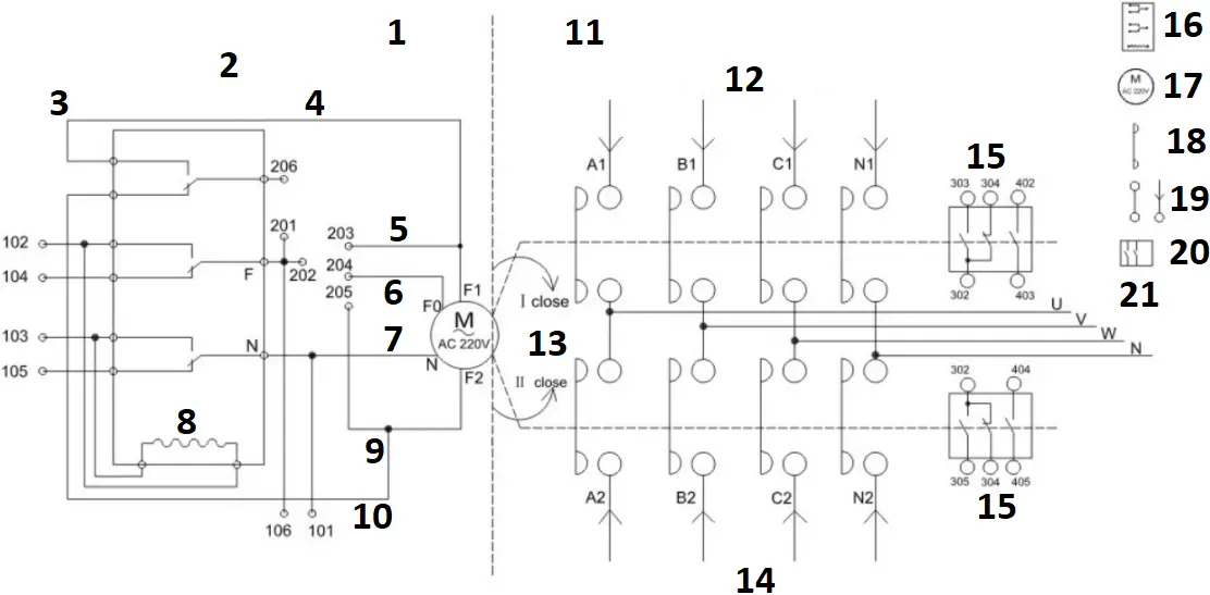
- The electrical part-3 section type
- Electronic control unit
- The working power supply input
No.1 terminal - The control signal input
No.2 terminal - clockwise rotation firewire input
- zero position control
- public zero line input
- electrical interlock relay
- counter clockwise rotation firewire input
- The working power supply signal output
No.1 terminals - The mechanical part -3 section type
- I POWER SUPPLY
- The mechanical interlocking
- II POWER SUPPLY
- The auxiliary circuit output
No.3/4 terminals - relay
- motor
- moving contact
- fixed contact
- position switch
- LOAD
![]() NOTE!
NOTE! ![]()
The above drawing is only a shematic diagram of its working principle, which does not represent the number of its internal components.
WARRANTY PROVISIONS 11
The international manufacturer warranty is 1 year. The warranty period starts from the date of purchase. In cases when warranty period is longer than 1 year according to local legislation please contact your local dealer. The Seller which sells the product is responsible for granting the warranty. Please contact the Seller for warranty. Within the warranty period, if the product fails because of defects in the production process, it will be exchanged on the same product or repaired.
The warranty card should be kept throughout the warranty period. In case of warranty card loss, a second one will not be provided. The customer must provide the warranty card and buyer`s check during request for repair or exchange. Otherwise, the warranty service will not be provided. The warranty card, attached to the product during sale, should be correctly and fully completed by the retailer and customer, signed and stamped. In other cases, warranty is not considered as valid.
Provide clean product to the service center. Parts, that must be replaced, are the property of the service center.
WARRANTY DOES NOT COVER:
– Mechanical damage (cracks, paint peeling, etc.) and damage caused by the action of aggressive media, ingress of foreign objects into the product or air inlet screen, as well as damage resulting from improper storage (corrosion of metal parts).
– Malfunctions resulting from improper operation, unintended use of the product, overloading of the product, as well as instability of the mains parameters. The product overload is indicated by melting or discoloration of parts due to the effect of high temperature, score marks on the cylinder or piston surfaces, destruction of connecting rod inserts or piston rings. In addition, the warranty obligations do not apply to the failure of the automatic voltage regulator of power generators due to improper operation.
– Malfunctions caused by contamination of the fuel or cooling system.
– Quick-wearing parts (V-belts, rubber seals, spark plugs, nozzles, clutch springs, pulleys, guide rollers, cables, manual starters, clamping chucks, collets, removable batteries, filter and safety elements, oil, removable devices, fittings, blades, drills, etc.).
– Electric cables with mechanical and thermal damage.
– The product tampered with or repaired not by the authorized service center. The product tampered with or repaired not by the authorized service center is indicated by, among other things, kinked splined parts of fasteners.
– Preventive maintenance (cleaning, washing, greasing, etc.), installation and setup of the product.
– Normal wear and tear of the product (remaining life).
– Malfunctions arising from the use of the product for business related purposes.
– The warranty card that is not filled out or does not bear the seller’s seal.
– The warranty card that does not bear the bearer’s signature.
– The warranty will become null and void in case of violation of the rules for the operation, transportation and storage of the generator.
– Improper or careless installation, improper connection to the mains.
ANNEX 
ONE-PHASE ATS ATS CONNECTION TERMINAL
Fig. 1
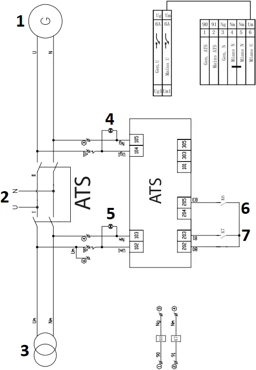
- GENERATOR
- LOAD OUTPUT
- MAINS
- GENERATOR INPUT
- MAINS INPUT
- GENERATOR CLOSE
- MAINS CLOSE
THREE-PHASE ATS ATS CONNECTION TERMINAL
Fig. 2
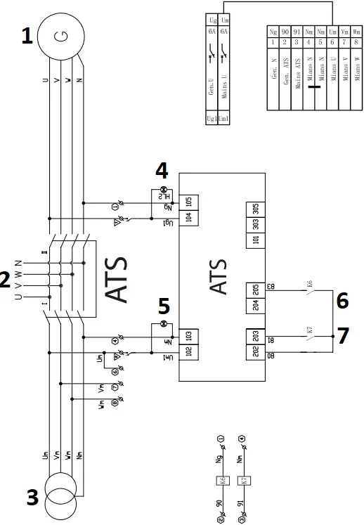
- GENERATOR
- LOAD OUTPUT
- MAINS
- GENERATOR INPUT
- MAINS INPUT
- GENERATOR CLOSE
- MAINS CLOSE
![]()
CONTACTS
Deutschland:
DIMAX International GmbH
Flinger Broich 203 -FortunaPark-
40235 Düsseldorf, Deutschland
www.koenner-soehnen.com
Ihre Bestellungen
[email protected]
Kundendienst, technische Fragen
und Unterstützung
[email protected]
Garantie, Reparatur und Service
[email protected]
Sonstiges
[email protected]
Polska:
DIMAX International
Poland Sp.z o.o.
Polska, Warczawska,
306B 05-082 Stare Babice,
[email protected]

 User Manual")


 User Manual")


