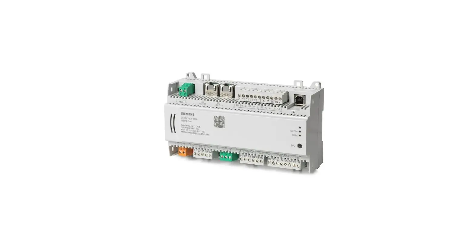
SIEMENS DXR2.M18 Room Automation Station
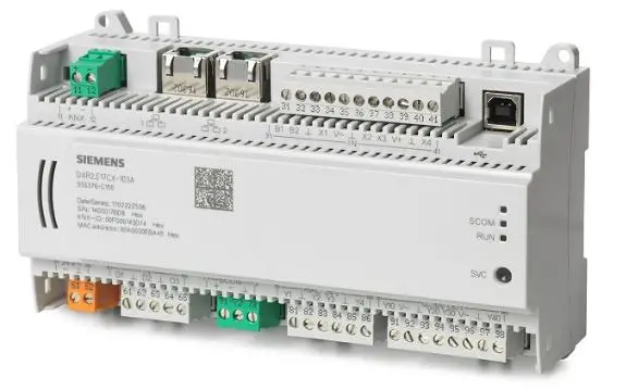
Automation station with increased functionality and flexibility to support the demands for standard control of terminal HVAC equipment and Total Room Automation (TRA) applications. TRA offers the highest level of flexibility for energy-optimized solutions without sacrificing comfort.
- Compact, programmable room automation stations for HVAC, lighting, and shading.
- BACnet MS/TP Communication (BTL certified).
- KNX PL-Link bus to connect sensors, actuators, and operator units (including bus power).
- USB interface.
- Operating voltage AC 24V.
- Mounted on standard DIN rails or on the wall.
- Plug-in terminal blocks.
Features
- Total Room Automation applications combining multiple disciplines (HVAC, lighting, blinds/shading) into one comprehensive solution.
- BTL Listed as a BACnet Advanced Application Controller (B-AAC) device.
- Fully programmable using block programming.
- Proven, pre-loaded applications.
- Operational modes (Comfort, Standby, Economy, Protection, and so on).
Preconfigured applications
Fan Coil Unit (FCU)
- FAN COIL 2-Pipe CW/HW and HW Valves
- FAN COIL 4-Pipe CW and HW Valves
- FAN COIL staged DX Cooling and staged Heating
- FAN COIL with CW and staged Electric Heat
- FAN COIL–UNIT VENT with CW, HW and Outside Air Damper (OAD) control
- FAN COIL–UNIT VENT with CW, ELEC and OAD control
- FAN-COIL-UNIT VENT with DX, HW and OAD control
- FAN COIL-UNIT VENT with DX, ELEC and OAD control
Chilled Beam
- Chilled Beam Passive 2 Pipe Heating/Cooling and Radiator 1-Stage Electric
Heat Pump
- HP Variable Speed, Two Stage Elec Heat and One Stage Elec Rad with OAD
- HP Variable Speed, Water Source, HW Heat and Modulating Elec Rad with OAD
- HP Single Stage, One Stage Elec Heat and HW Rad with OAD
- HP Multi Stage, Two Stage Elec Heat and HW Rad with OAD
- HP Multi Stage, Hot Gas Reheat, One Stage Elec Heat and HW Rad with OAD
- HP Multi Stage, Ground Source, Hot Gas Reheat, One Stage Elec Heat and HW Rad with OAD
Additional Applications
- Electrical terminal heating coils, PWM, single, multi-stage or analog
- Terminal fans, single, multi-stage or analog
- Chill water, DX or hot water coils and heating/cooling coils (2-pipe or 4-pipe)
- Variable Air Volume (VAV), Dual Duct and Fan Powered VAV (FPB)
- Radiant ceiling including Chilled beams, cooling, heating and heating/cooling (2-pipe or 4-pipe) control
- Radiator/Baseboard: hot water, steam or electric
- Lighting – up to four separated or overlapping zones
- Manual switching and dimming
- Occupancy control and Vacancy control
- Automatic Daylight Harvesting – step or constant level control
- Stairwell lighting
- Scene control
- Blinds – one or two separate zones
- Manual control: Up, Down, Predefined positions
- Occupancy control and Vacancy control
- Glare Protection
- Energy efficiency functions including solar radiation optimization
- Slat angle
- Scene control
Pre-loaded Application Options
Fan coil unit
- Single, multiple or variable speed fan control.
- Outside air damper control with economizer.
- Ventilation Control or Demand Control Ventilation (DCV) with separate outside air damper (OAD) setpoints for each operational mode.
- Supply (discharge) air temperature control for modulation heating or cooling coils.
- Dehumidification control.
- Terminal coils: heating (hot water or electric), cooling (chilled water or DX) and heating/cooling coil (2-pipe or 4-pipe).
- Radiant ceiling including Chilled beams and Radiator control.
Heat pump
- Heat Pump compressors: Single, multiple or variable speed.
- Air-to-air, water loop or ground water configurations.
- Single, multiple or variable speed fan control.
- Outside air damper control with economizer.
- Dehumidification control.
- Ventilation Control or Demand Control Ventilation (DCV) with separate outside air damper (OAD) setpoints for each operational mode.
- Terminal heating coil (hot water or electric) or hot gas coil.
- Radiant ceiling including Chilled beams and Radiator control.
- Greenleaf energy efficiency determination and display.
- Configurable plant operating modes (heating, cooling, warm up, cool down, flush/purge, and so on).
Functions
The selected application and its parameters as well as input and output configuration determine the room automation station’s functionality.
A detailed description of functionality is available in the ABT (Automation Building Tool) online help.
Communication
- BACnet MS/TP
- USB connection for service and commissioning, firmware download, and LAN access.
- The following functions are available with the KNX PL-Link bus:
- Communication with room operator units, switches, sensors, actuators, and luminaires.
- Plug-and-play connection of Siemens field devices with KNX PL-Link.
Type summary
| Product Number | SSN | Description | Inputs | Outputs |
| DXR2.M18-101B (Version with 60 data points*) | S55376-C124 | DXR2.M18 Room Automation Station | 2 DI, 4 UI | 8 DO Triacs, 4 AO 0 to 10V |
| DXR2.M18-101K (Version with 60 data points) | S55376-C154 | Smoke Control DXR2.M18 Room Automation Station | 2 DI, 4 UI | 8 DO Triacs, 4 AO 0 to 10V |
Accessories
| Product Number | Designation |
| 985-124 | 499 ohm Resistor Kit |
Product Documentation
| Topic | Title | Document ID |
| Installation and mounting | DXR Installation Instructions | A6V10550039 |
| Global datasheet* | DXR2 24V IP DXR2 24V MS/TP | N9205 N9207 |
| Setup and commissioning | DXR VAV Start-up Procedures DXR FPB Start-up Procedures DXR FCU Start-up Procedures Balancing Procedures | A6V10665935 A6V10665938 A6V10665941 A6V10665943 |
| Room Unit Datasheet | Wall mounted | A6V10394781 |
| BTL listing | DXR PIC Statement | A6V10665948 |
Please see the Global datasheets for additional information not found in this submittal sheet.
Technical data
Housing
| Color | RAL 7035 (light-gray) |
| Dimensions | 180 mm (7.09 in) x 104.5 mm (4.11 in) x 59.5 mm (2.34 in) |
| Weight Packaging | ca. 360 g (12.69 oz) ca. 40 g (1.41 oz) |
Function data
| Communication | |
| A/D Resolution (analog in) D/A Resolution (analog out) | 14 Bits 12 Bits |
Power data
| Power supply | |
| Operating voltage | AC 24V -15%/+20% |
| Frequency | 50/60 Hz |
| Internal fuse | 4 A irreversible |
| Transformer with secondary current limitation of max. 10 A or external secondary current fuse Non-renewable fuse Circuit breakers | Max. 10 A, slow Max. 13 A, characteristic B, C, D as per EN 60898 |
| Apparent power (VA) for transformer design | ||||||
| Base Model | Base load | Max. load Triac output AC 24V~ 0.25 A each | Max. load all Aux. outputs AC 24V~ | Max. load KNX PL-Link (at 50 mA) | Max. load DC 24V+ (2.4 W)) | Max. Allowed Power consumption including connected field devices |
| DXR2.M18 | 6 | 8 x 6 = 48 | 18 | 4 | 6 | 70 |
Power for the Triac outputs must be reduced if the maximum load of 18 VA is required for AC 24V field supply on the DXR2.x18.
NOTE:
To calculate the total VA, add the Base Load + the number of Triacs + field supplies+ KNX PL-Link devices.
This cannot exceed the maximum power consumption. See the Wiring Guidelines for more information.
Inputs
| Analog Inputs | ||
| Resistance sensor | Temperature measurement | Voltage measurement |
| AI 1000 Ω | AI PT1K 375 (NA)*) | AI 0 to 10V |
| AI 2500 Ω | AI PT1K 385 (EU)*) | AI 0 to 10V (0 to 100%) |
| AI 10 KΩ | AI (LG-)Ni1000*) | |
| AI 100 KΩ | AI Ni1000 DIN*) | |
| AI T1 (PTC)*) | ||
| AI NTC10K (Type II)**) | ||
| AI NTC100K**) | ||
A fixed value of 1 Ω is calibrated to correct line resistance.
Configurable default.
| Digital Inputs | |
| Contact voltage | Universal input: 18V Digital input: 21V |
| Contact current | Universal input: 1.2 mA; 7.4 mA initial current Digital input: 1.6 mA; 9.4 mA initial current |
| Contact resistance for closed contacts | Max. 100 Ω |
| Contact resistance for open contacts | Min. 50 kΩ |
Outputs
| Analog Outputs | |
| 0 to 10V | Max. 1 mA |
| Digital Outputs | |
| Type (Switching outputs triacs) | High side The Triac closes the contact to AC 24V |
| Switching voltage | AC 24V |
| Permissible load | 250 mA/6 VA per output (cos phi 0.35) (500 mA/12 VA per output with PWM*) |
| Protection | Short-circuit proof |
| DC 24V output for field devices (1: V+) | |
| Output voltage | DC 24V |
| Permissible load | 100 mA/2.4 W |
| Protection against overload | Short-circuit proof |
Connections
| Interfaces | |
| MSTP | Interface type: RS485 Galvanic isolation: Yes Baud rates: 9600, 19200, 38400, 57600, 115200 Protocol: BACnet over MS/TP Short-circuit proof Protection against faulty wiring at max. AC 24V |
| USB (2.0) | Plug: Type B Data rate: 12 Mbps |
| KNX PL-Link | Type: KNX TP1 PL-Link, galvanic isolation Baud rate: 9.6 kbps Bus power: 50 mA Short-circuit proof Protection against faulty wiring at max. AC 24V |
| Wiring connections | |
| Pluggable screw terminals | Copper wire or copper strands with ferrules 1 x 0.6 mm dia. to 2.5 mm2 (22 to 14 AWG) or 2 x 0.5 mm dia. to 1 mm2 (24 to 18 AWG) Copper strands without ferrules 1 x 0.6 mm dia. to 2.5 mm2 (22 to 14 AWG) or 2 x 0.5 mm dia. to 1.5 mm2 (24 to 16 AWG) |
| Slotted screws | Small 1/8” blade, tightening torque 0.6 Nm (0.44 lb-ft) |
| Wiring lengths for signals | KNX PL-Link 80 m (260 ft) with internal bus power or 300 m (990 ft) with external power supply MS/TP 1,000 m (3,290 ft) Signal lines 80 m (260 ft) For inputs AI 100 KΩ, AI NTC10K, AI NTC100K: 30 m (100 ft) or 80 m (260 ft), if shielded. |
| KNX/PL-Link Network and Power Wriring.* | |
| Cable configuration | 1 or 2 twisted pair – Pair 1 red/black – Pair 2 yellow/white |
| Gauge | 20 AWG (solid copper) |
| Twists per foot | 4 Minimum |
| Capacitance | 30 pF/foot or less |
| Shields | 100% foil with drain wire |
| UL type | 300Vrms, CMP (75 °C or higher) |
| CSA type | 300Vrms, FT6 (75 °C or higher) |
Alternative 18 AWG STP CMP (Belden 6320FE 8771000)
Conformity
CAUTION
National safety regulations
Failure to comply with national safety regulations may result in personal injury and property damage.
Observe national provisions and comply with the appropriate safety regulations.
| Ambient Conditions and Protection classification | |
| Climatic ambient conditions ● Transport and storage ● Operation | ● Temperature -25 to 70°C (-13 to 158°F) Air humidity 5 to 95% rh. ● Temperature -5 to 45°C (23 to 113°F)/ -5 to 50°C (23 to 122°F) Air humidity 5 to 95% rh. |
| Standards, Directives and Approvals | |
| UL Listing | UL 916 PAZX – Conforms to UL916 9th and 10th Edition. UL 864 UUKL Smoke Control Equipment – Conforms to UL864 9th and 10th Edition. (Smoke Control ‘K’ variant only) |
| Suitable for plenum area installation | UL1995 |
| Federal Communications Commission | FCC CFR 47 Part 15 Class B |
| CSA Compliance and cUL certification | C22.2 No. 205 |
| Environmental compatibility – RoHS Compliant | The product environmental declaration contains data on environmentally compatible product design and assessments (composition, packaging, environmental benefit, and disposal). |
| BACnet BTL Listing | BTL-AAC |
| CEC Title 24 Supported | — |
| ASHRAE 90.1 Supported | — |
| Quality | ISO 9001 (Quality) |
Issued by Siemens Industry, Inc. Smart Infrastructure 1000 Deerfield Pkwy Buffalo Grove IL 60089 Tel. +1 847-215-1000
© Siemens Industry, Inc., 2020 Technical specifications and availability subject to change without notice.


