
Milesight UC100 Featuring LoRaWAN IoT Controller User Guide
Safety Precautions
Milesight will not shoulder responsibility for any loss or damage resulting from not following the instructions of this operating guide.
- The device must not be remodeled in any way.
- Do not place the device close to objects with naked flames.
- Do not place the device where the temperature is below/above the operating range.
- Power off the device when installing or wiring.
- Make sure electronic components do not drop out of the enclosure while opening.
- The device must never be subjected to shocks or impacts
Declaration of Conformity
UC100 is in conformity with the essential requirements and other relevant provisions of theCE, FCC, and RoHS.

Copyright © 2011-2022 Milesight. All rights reserved.
All information in this guide is protected by copyright law. Whereby, no organization or individual shall copy or reproduce the whole or part of this user guide by any means without written authorization from Xiamen Milesight IoT Co., Ltd.

For assistance, please contact
Milesight technical support:
Email: [email protected]
Tel: 86-592-5085280
Fax: 86-592-5023065
Address: Building C09, Software ParkIII, Xiamen 361024, China
Revision History
| Date | Doc Version | Description |
| May 27, 2022 | V 1.0 | Initial version |
Product Introduction
Overview
UC100 is an IoT controller used for remote control and data acquisition from Modbus RS485 devices via LoRa WAN® networks. It can read up to 16 Modbus RTU devices and support Modbus transparent transmission between server and RS485 devices as a Modbus to LoRaWAN®converter. Besides, UC100 supports multiple trigger conditions and actions which can work autonomously even when the network drops.
Features
- Easy to connect with diverse wired sensors through RS485 interfaces
- Support LoRaWAN® wireless communication
- Multiple triggering conditions and actions
- Embedded watchdog for work stability
- Industrial metal case design with a wide operating temperature range
- Compliant with standard LoRaWAN® gateways and network servers
- Quick and easy management with Milesight IoT Cloud solution
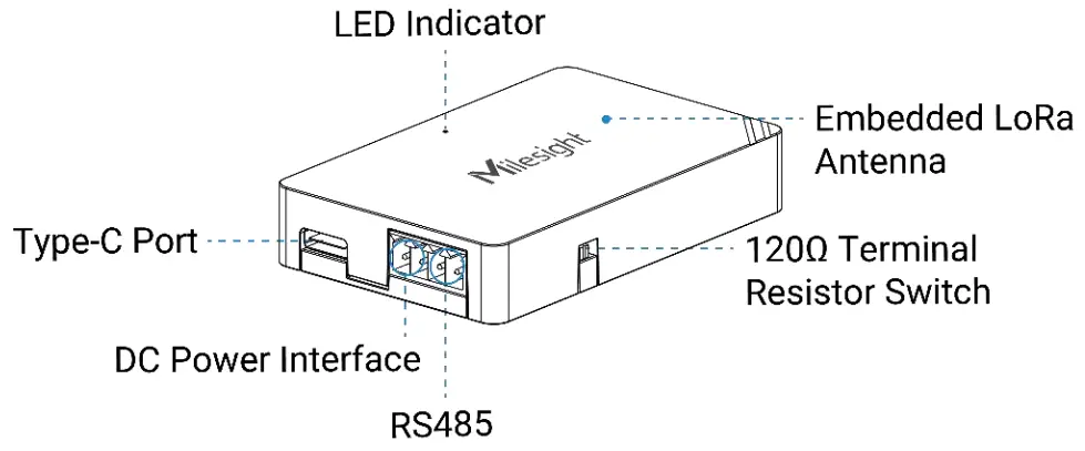
Hardware Introduction
Packing List
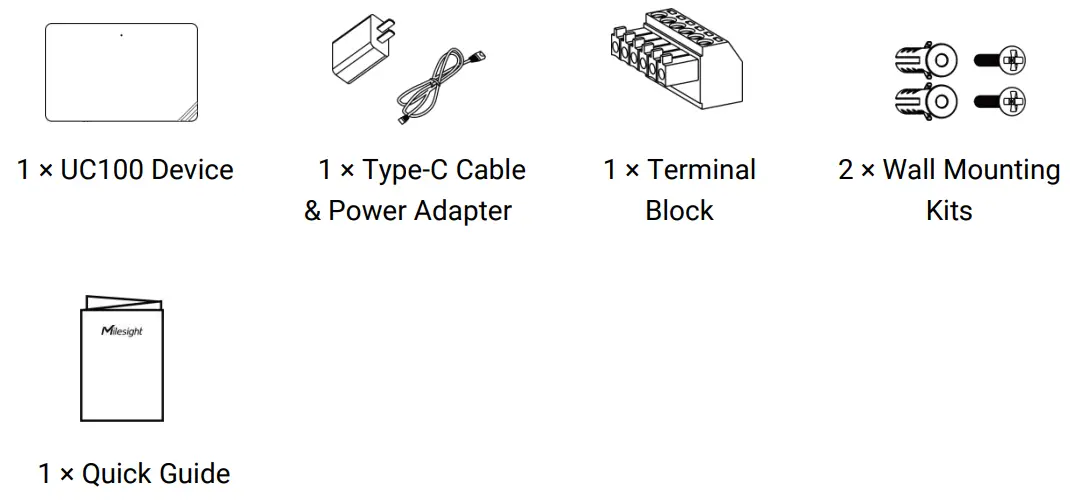
 If any of the above items are missing or damaged, please contact your sales representative.
LED Patterns and Reset Button
The reset button is inside the device.
| Device Status | LED Status |
| System is functioning properly | Static On |
| Reboot: hold the reset button inside the device for more than 3 seconds | Static On → Slowly Blinks |
| Reset to factory default: hold the reset button inside the device for more than 10 seconds | Static On → Quickly Blinks |
| Fail to acquire data from data interfaces | Slowly Blinks |
| Device upgrade or system error | Static On |
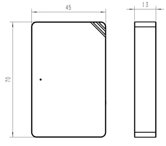
Dimensions (mm)
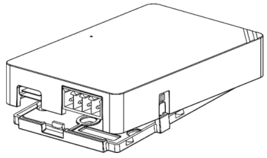
Device Installation
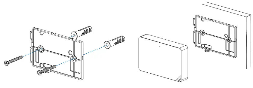
UC100 device can be placed on a desktop or mounted to a wall.
- Take off the back cover of UC100 device, and fix the wall plugs into the wall according to the drilling position as referred.

- Screw the cover on the mounting positions and install back the device.

Operation Guide
Log in the ToolBox
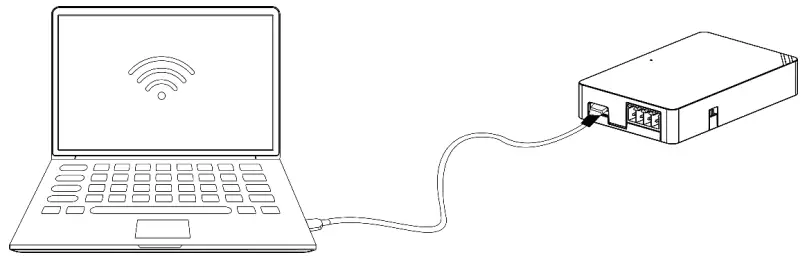
- Download ToolBox software from Milesight IoT website.
- Power on the UC100 device, then connect it to computer via the type-C port

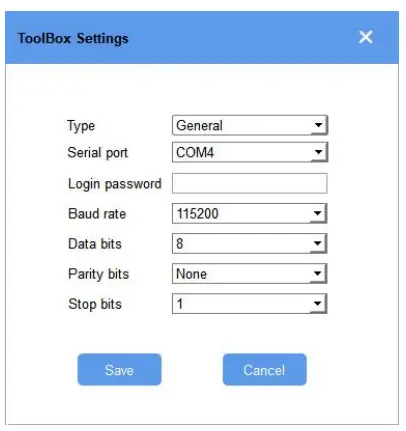
- Open the ToolBox and select type as “General”, then click password to log in ToolBox. (Default password: 123456)

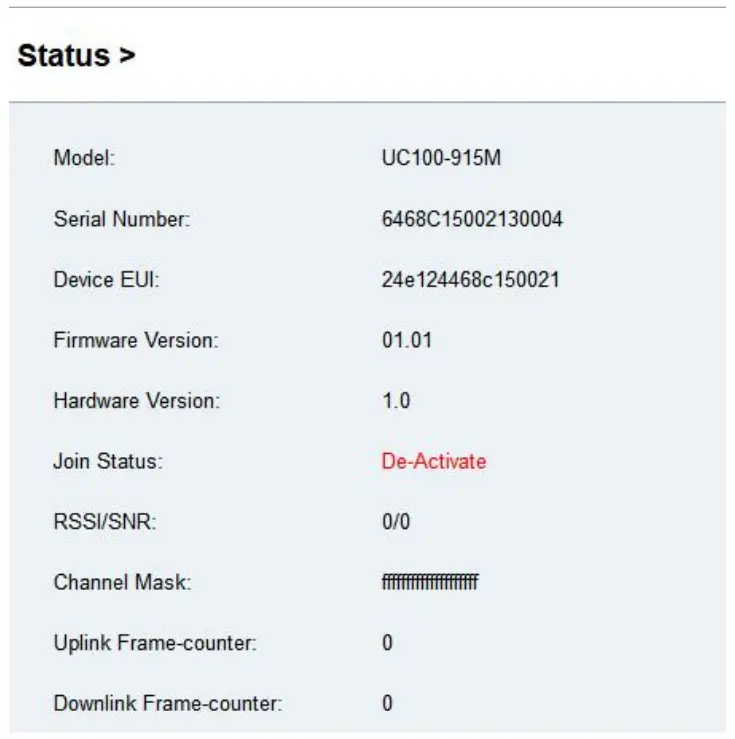
- After logging in the ToolBox, you can change device settings.

LoRaWAN Settings
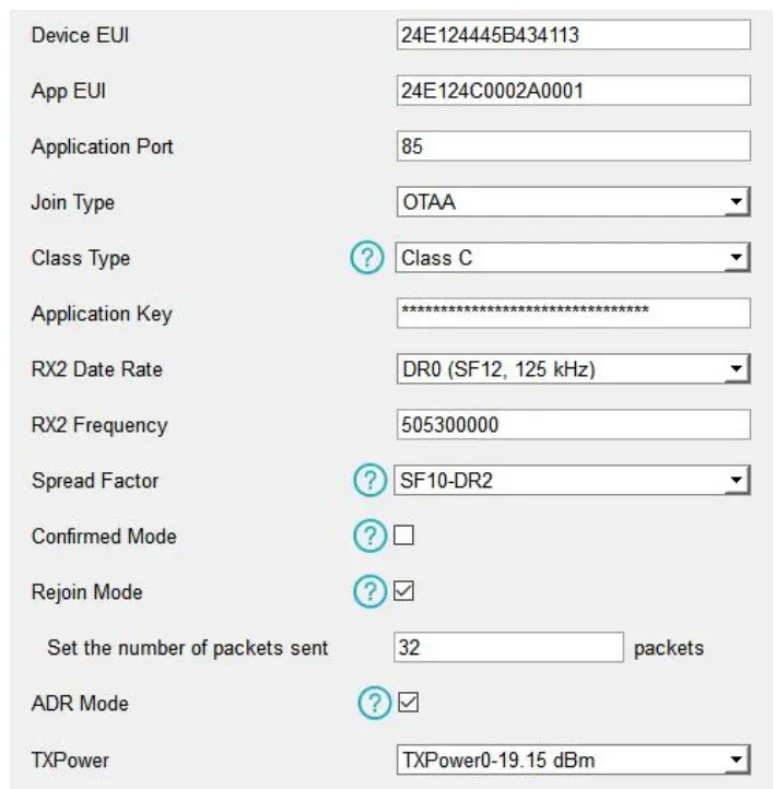
LoRaWAN settings are used for configuring the transmission parameters in LoRaWAN® network. Basic LoRaWAN Settings:
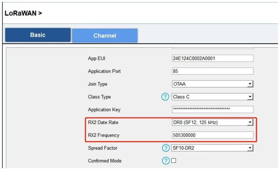
Go to “LoRaWAN Settings -> Basic” to configure join type, App EUI, App Key andother information. You can also keep all settings by default.
| Parameters | Description |
| Device EUI | Unique ID of the device on the label. |
| App EUI | Default App EUI is 24E124C0002A0001. |
| Application Port | The port is used for sending and receiving data, the default port is 85. |
| Working Mode | Fixed as Class C. |
| Join Type | OTAA and ABP modes are available. |
| Application Key | Appkey for OTAA mode, default is 5572404C696E6B4C6F52613230313823. |
| Device Address | DevAddr for ABP mode, default is the 5th to 12th digits of SN. |
| Network Session Key | Nwkskey for ABP mode, default is 5572404C696E6B4C6F52613230313823. |
| Application Session Key | Appskey for ABP mode, default is 5572404C696E6B4C6F52613230313823. |
| RX2 Data Rate | RX2 data rate to receive downlinks. |
| RX2 Frequency | RX2 frequency to receive downlinks. Unit: Hz |
| Spread Factor | If ADR is disabled, the device will send data via this spread factor. |
| Confirmed Mode | If the device does not receive ACK packet from network server, it will resend data 3 times at most. |
| Rejoin Mode | Reporting interval ≤ 30 mins: the device will send a specific number of LinkCheckReq MAC packets to the network server every 30 mins to validate connectivity; If there is no response, the device will re-join the network. Reporting interval > 30 mins: the device will send a specific number of LinkCheckReq MAC packets to the network server every reporting interval to validate connectivity; If there is no response, the device will re-join the network. |
| Set the number of packets sent | When rejoin mode is enabled, set the number of LinkCheckReq packets sent. |
| ADR Mode | Allow the network server to adjust datarate of the device. |
| Tx Power | Transmit power of device. |
Note
- Please contact sales for device EUI list if there are many units.
- Please contact sales if you need random App keys before purchasing.
- Select OTAA mode if you use Milesight IoT Cloud to manage devices.
- Only OTAA mode supports rejoin mode.
LoRaWAN Frequency Settings:
Go to “LoRaWAN Settings -> Channel” to select supported frequency and select channelstosend uplinks. Make sure the channels match what you set in the LoRaWAN® gateway.
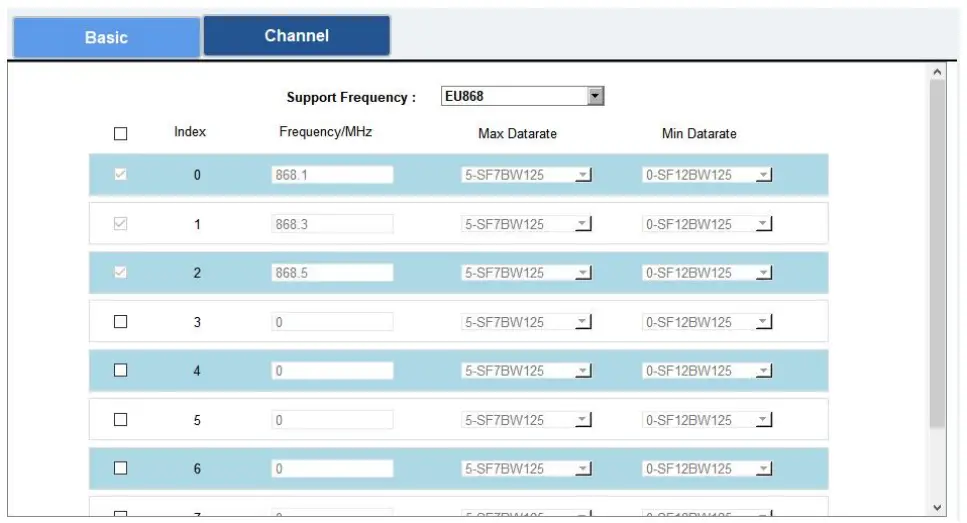
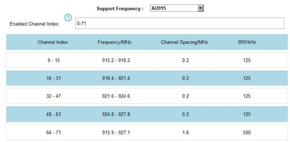
If frequency is one of CN470/AU915/US915, you can enter the index of the channel that youwant to enable in the input box, making them separated by commas.
Examples:
1, 40: Enabling Channel 1 and Channel 40
1-40: Enabling Channel 1 to Channel 40
1-40, 60: Enabling Channel 1 to Channel 40 and Channel 60
All: Enabling all channels
Null: Indicates that all channels are disabled
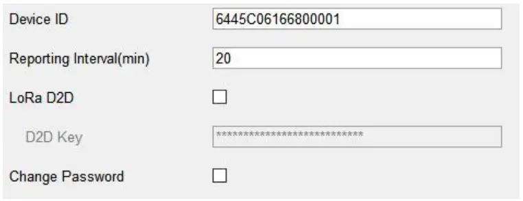
General Setting
Basic Setting
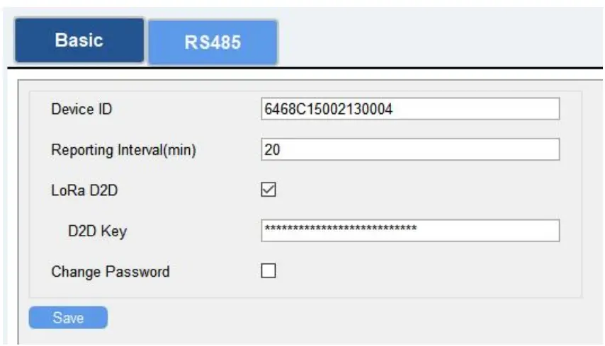
| Parameters | Description |
| Device ID | Show the SN of the device. |
| Reporting Interval | Reporting interval of transmitting data to the network server. Range: 1-1080 mins, default: 20 mins |
| LoRa D2D | See details on chapter 4.5. |
| Change Password | Change the password to log in ToolBox. |
RS485 Settings
UC100 has one RS485 port for Modbus RTU device connection.
- Connect RS485 device to RS485 port.
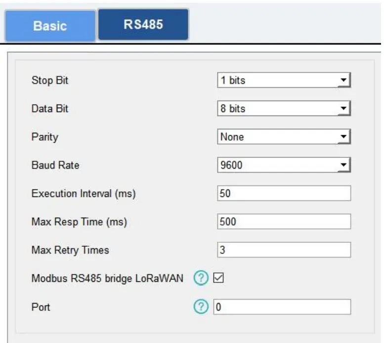
- Go to “General -> RS485” to enable RS485 and configure serial port settings. Serial port settings should be the same as the RS485 terminal devices.

Parameters Description Stop Bit 1 bit/2 bit are available. Data Bit 8 bit is available. Parity None, Odd and Oven are available. Baud Rate 1200/2400/4800/9600/19200/38400/57600/115200 are available. Execution Interval (ms)
The execution interval between each Modbus channel command. Max Resp Time (ms)
The maximum response time that the UC100 waits for the reply to the command. If it does not get a response after the max response time, it is determined that the command has timed out.
Max Retry Time (ms) Set the maximum retry times after the device fails to read data from RS485 terminal devices. Modbus RS485 bridge LoRaWAN If this mode is enabled, the device will transmit Modbus RTU commands from the network server to RS485 terminal devices transparently and send Modbus reply originally back to the network server.
Port: Select from 2-84, 86-223. - Click
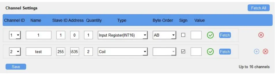
 to add Modbus channels, then save configurations.
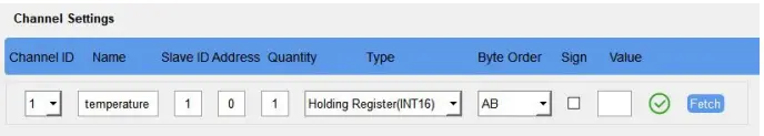
Parameters Description Channel ID Select the channel ID you want to configure from 16 channels. Name Customize the name to identify every Modbus channel. Slave ID Set Modbus slave ID of a terminal device. Address The starting address for reading. Quantity Set read how many digits from starting address, it fixes to 1. Type Select the data type of Modbus channels. Byte Order Set the Modbus data reading order if you configure the type as Input register or holding register. INT32/Float: ABCD, CDBA, BADC, DCBA
INT16: AB, BA
Sign The tick indicates that the value has a plus or minus sign. Fetch After clicking, UC100 will send Modbus read command to test if it can read correct values. Example: as this setting, the device will send command: 01 03 00 00 00 01 84 0A

- Click “Fetch” to check if UC100 can read correct data from terminal devices

Note: Do not click “Fetch” frequently since the response time to reply is differ for every terminal device.

IF-THEN Command
UC100 supports configuring locally IF-THEN commands to do some actions automatically evenwithout a network connection. One device can be added 16 commands at most.
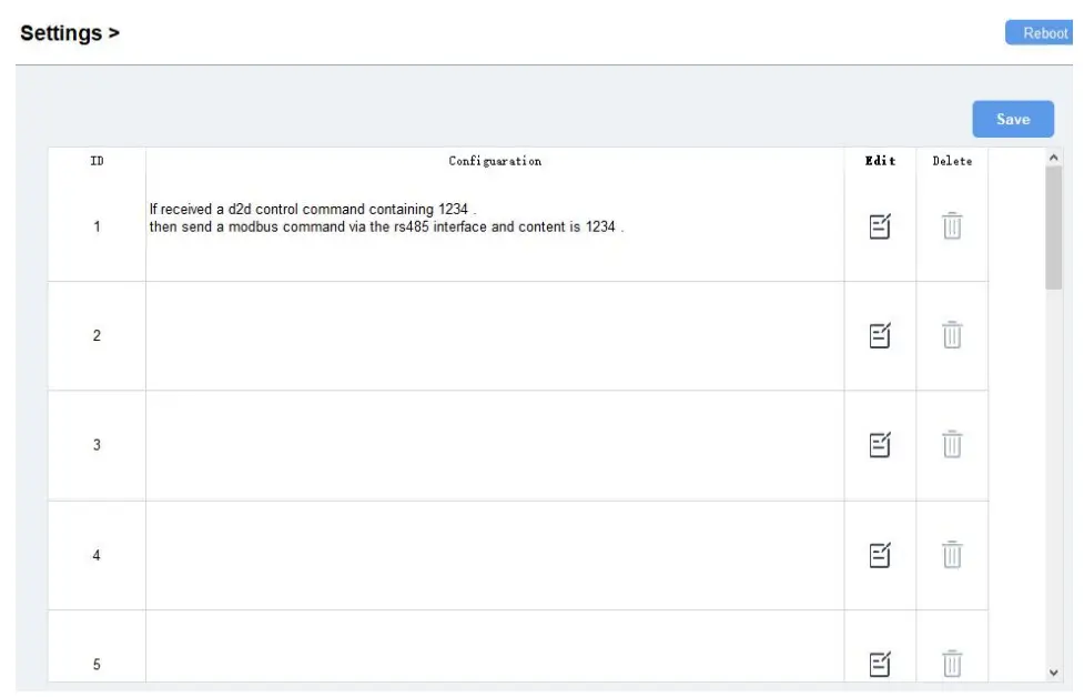
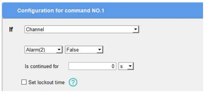
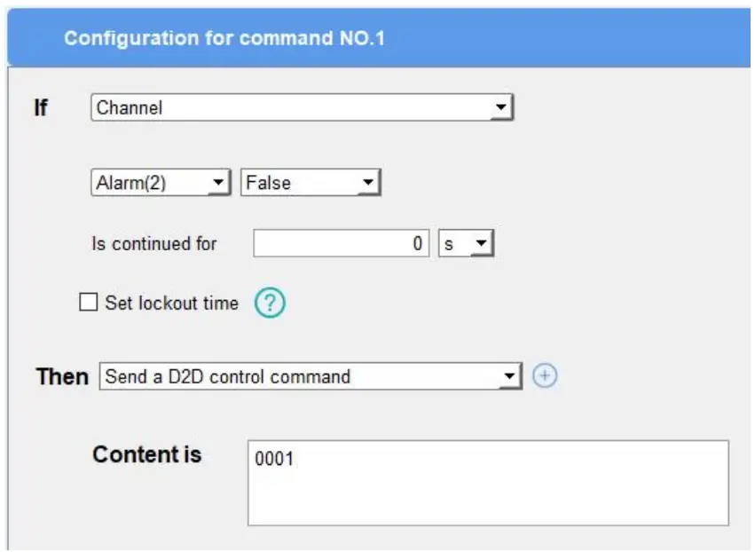
- Go to “Command” page, and click “Edit” to add commands.

- Set an IF condition based on the terminal device data or UC100 device status.

Condition Description Channel When UC100 device gets certain response (False, True, Above, Below, Within) in certain RS485 channel (Channel Name + Channel ID), this command is triggered.
Is continued for: the updated value should last for some time that is longerthan a sole reporting interval. Set lockout time: after the lockout time, UC100 will check if the latest RS485 response matches the condition still. 0 means this IF condition will only be
detected once.
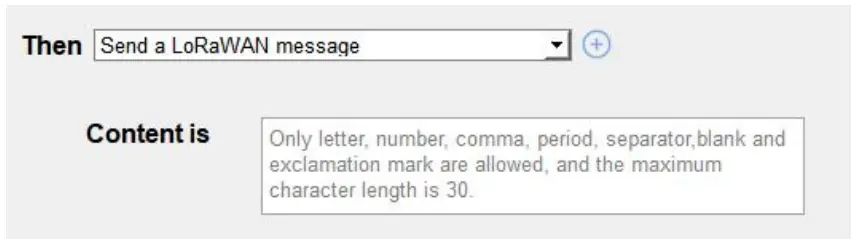
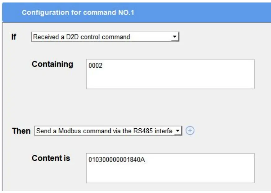
Received a D2D control command This only works with the LoRa D2D feature enabled. See details on chapter 4.5. - Set THEN action according to your request. You can add at most 3 actions

Action Description Send a LoRaWAN message Send a custom message to the network server. Restart the Device Reboot the device. Send a D2D control command This only works with LoRa D2D feature enabled. See details on chapter 4.5. Send a Modbus command via the RS485 interface This only works with LoRa D2D feature enabled. See details on chapter 4.5.
LoRa D2D Settings
LoRa D2D protocol is developed by Milesight and used for setting up transmission amongMilesight devices without a gateway. When the LoRa D2D setting is enabled, UC100 can workasa LoRa D2D controller to send control commands to other devices or work as a LoRa D2Dagent to receive commands to trigger a reboot or message to the network server.
- Go to “General -> Basic” page, enable LoRa D2D feature, and define a unique LoRaD2D key which is the same as LoRa D2D controller or agent devices. (Default LoRaD2DKey: 5572404C696E6B4C6F52613230313823)

- Go to “LoRaWAN Settings -> Basic” to configure the RX2 datarate and RX2 frequency. WhenUC100 works as LoRa D2D controller, it will send commands as RX2 settings.

- Go to “Command” page to set corresponding operations. When the RS485 channel triggers, UC100 can work as LoRa D2D controller to send a control command to control the LoRa D2D agent device. The command should be a 2-byte hexadecimal number.

When UC100 receives a LoRa D2D command, it can work as a LoRa D2D agent to reboot thedevice or send Modbus command to RS485 terminal devices.
Maintenance
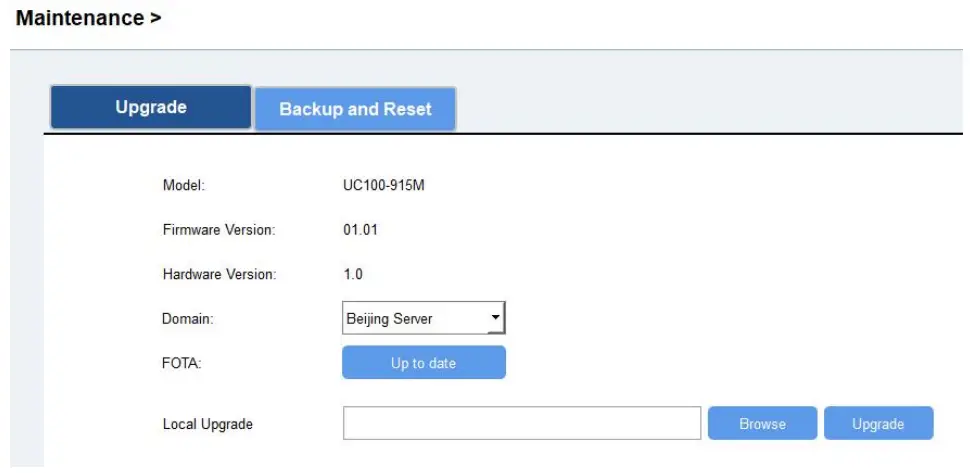
Upgrade
UC100 supports upgrade firmware locally via ToolBox software.
- Download firmware from www.milesight-iot.com to your PC.
- Go to “Maintenance -> Upgrade”, click “Browse” to import firmware and upgrade the device. You can also click “Up to Date” to search for the latest firmware of the device and upgrade.
Note: Any operation on ToolBox is not allowed during upgrading, otherwise the upgrading will be interrupted, or even the device will break down.
Backup
UC100 devices support configuration backup for easy and quick device configuration in bulk. Backup is allowed only for devices with the same model and LoRa frequency band.
- Go to “Maintenance -> Backup and Reset”, and click “Export” to save the current configuration as json format backup file.
- Click “Browse” to select the backup file, then click “Import” to import the configurations.

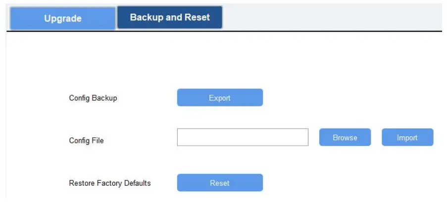
Reset to Factory Default
Please select one of following methods to reset device:
Via Hardware: Open the case of UC100, and hold the reset button for more than 10s until theLED blinks.
Via ToolBox Software: Go to “Maintenance -> Backup and Reset” to click “Reset”.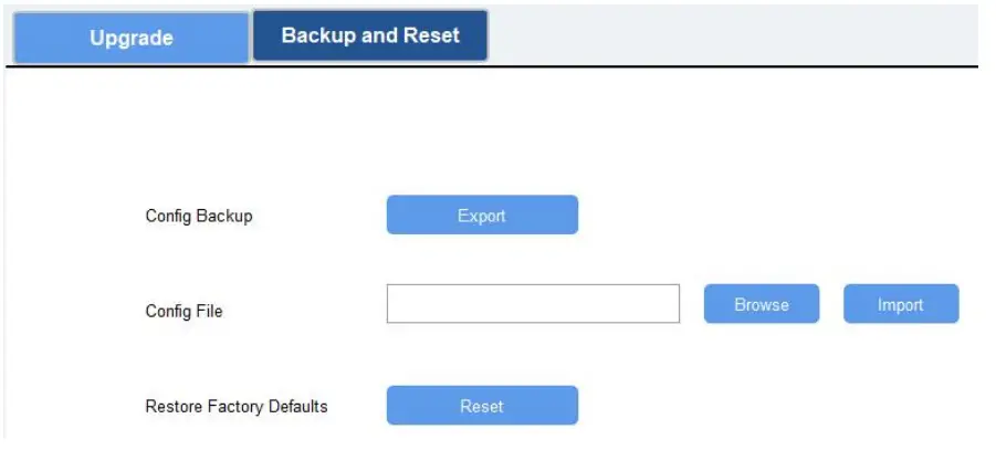
Device Payload
All data are based on the following format (HEX):
| Channel1 | Type1 | Data1 | Channel2 | Type2 | Data2 | Channel 3 | … |
| 1 Byte | 1 Byte | N Bytes | 1 Byte | 1 Byte | M Bytes | 1 Byte | … |
Among them, Data field are shown as little endian. For decoder examples, you can find them at https://github.com/Milesight-IoT/SensorDecoders.
Device Information
UC100 reports basic device information of device every time joining the network.
| Channel | Type | Data Size/Byte | Description |
| ff | 01 (Protocol Version) | 1 | 01 => V1 |
| 09 (Hardware Version) | 2 | 01 20 => V1.2 | |
| 0a (Software Version) | 2 | 01 01 => V1.1 | |
| 0b (Power event) | 1 | ff => powered on | |
| 16 (Device SN) | 8 | 64 45 B4 34 11 30 00 01 => SN is 64 45 B4 34 11 30 00 01 |
Example:
| ff0bff ff0101 ff166445b43411300001 ff090100 ff0a0101 | ||
| Channel | Type | Value |
| ff | 0b (Power Event) | ff (powered on) |
| ff | 01 (Protocol Version) | 01 (V1) |
| ff | 16 (Device SN) | 64 45 B4 34 11 30 00 01 |
| ff | 09 (Hardware Version) | 0100 (V1.0) |
| ff | 0a (Software Version) | 0101 (V1.1) |
Sensor Data
UC100 reports RS485 sensor data according to reporting interval (20 mins by default).
| Channel | Type | Byte | Description | |||
| ff | 19 (RS485) | Mutable (4-7) | Total: Byte 1+Byte 2+Byte 3+Value Byte 1: Channel ID Byte 2: Data Size Byte 3: Data Type | |||
| Code | Data Type | |||||
| 00 | Coil | |||||
| 01 | Discrete | |||||
| 02 | Input16 | |||||
| 03 | Hold16 | |||||
| 04 | Hold32 | |||||
| 05 | Hold_float | |||||
| 06 | Input32 | |||||
| 07 | Input_float | |||||
| 08 | Input_int32_with upper | |||||
| 16 bits | ||||||
| 09 | Input_int32_with lower 16 bits | |||||
| 0a | Hold_int32_with upper 16 bits | |||||
| 0b | Hold_int32_with lower 16 bits | |||||
| ff | 15 (Modbus collecting exception) | 1 | Channel ID of failed Modbus collection. | |||
Note: Channel ID can be configured in ToolBox.
| Channel ID | Description |
| 00 | RS485 (Modbus Master) Channel 1 |
| 01 | RS485 (Modbus Master) Channel 2 |
| 02 | RS485 (Modbus Master) Channel 3 |
| … | … |
| 0f | RS485 (Modbus Master) Channel 16 |
Examples:
| ff 19 07 02 03 15 00 | |||||
| Channel | Type | Channel ID | Data Size | Data Type | Value |
| ff | 19 | 07 => | 02 => | 03 => Hold | 15 00 => |
| (RS485) | Channel 8 | 2 bytes | 16 | 00 15 = 21 | |
Note: When data type is holding register or input register, ToolBox can set different byte orders. Take below Modbus register response from RS485 sensors as example:
| Register Address | Value (Hex) |
| 0 | 00 15 |
| 1 | 00 20 |
When using different byte orders, you can use ToolBox to fetch different results, and the device will upload data with little endian order.
| Data Type | Byte Order | Fetch Result | Uplink (HEX) |
| Holding/Input Register (INT16) | AB | 21 (0x15) | 15 00 (BA) |
| BA | 5376 (0x1500) | 00 15 (AB) | |
| Holding/Input Register (INT32) | ABCD | 1376288 (0x00150020) | 20 00 15 00 (DCBA) |
| CDAB | 2097173 (0x00200015) | 15 00 20 00 (BADC) | |
| BADC | 352329728 (0x15002000) | 00 20 00 15 (CDAB) |
| DCBA | 536876288 (0x20001500) | 00 15 00 20 (ABCD) | |
| Holding/Input Register (INT32 with upper 16 bits) | / | 21 (0x15) | 15 00 00 00 |
| Holding/Input Register (INT32 with lower 16 bits) | / | 32 (0x20) | 20 00 00 00 |
If UC100 fails to connect the Modbus data, it will send an error message.

| ff 15 00 | ||
| Channel | Type | Value |
| ff | 15 (Poll Failed) | 00 => Channel 1 |
Downlink Command
UC100 supports downlink commands to configure the device. The application port is 85 by default.
| Channel | Type | Description |
| ff | 03(Set Reporting Interval) | 2 Bytes, unit: s |
| 10 (Reboot) | ff (Reserved) |
Examples:
- Reporting Interval
ff 03 b0 04 Channel Type Value ff 03 (Set Reporting Interval) b0 04 => 04 b0 = 1200 s = 20 mins - Reboot the device
ff 10 ff Channel Type Reserved ff 10 (Reboot) ff


