![]()
![]() AI Workplace Sensor
AI Workplace Sensor
Featuring LoRaWAN®
VS121
User Guide
Safety Precautions
Milesight will not shoulder responsibility for any loss or damage resulting from not following the instructions of this operating guide.
- The device must not be disassembled or remodeled in any way.
- To avoid risk of fire and electric shock, do keep the product away from rain and moisture before installation.
- Do not place the device where the temperature is below/above the operating range.
- Do not touch components which may be hot.
- The device must never be subjected to shocks or impacts.
- Make sure the device is firmly fixed when installing.
- Make sure the plug is firmly inserted into the power socket.
- Do not expose the device to where a laser beam equipment is used.
- Use a soft, dry cloth to clean the lens of the device. Stubborn stains can be removed using a cloth dampened with a small quantity of detergent solution, then wipe them dry.
Declaration of Conformity
VS121 is in conformity with the essential requirements and other relevant provisions of the CE, FCC, and RoHS.
Copyright © 2011-2022 Milesight. All rights reserved.
All information in this guide is protected by copyright law. Whereby, no organization or individual shall copy or reproduce the whole or part of this user guide by any means without written authorization from Xiamen Milesight IoT Co., Ltd.
 For assistance, please contact
Milesight technical support:
Email: [email protected]
Tel: 86-592-5085280
Fax: 86-592-5023065
Address: Building C09, Software Park
Phase III, Xiamen 361024,
China
Revision History
| Date | Doc Version | Description |
| Apr. 26, 2021 | V 1.0 | Initial version |
| Jan. 18, 2022 | V 1.1 | 1. Support line crossing counting feature; 2. Support LoRa D2D feature; 3. Support people counting debounce; 4. Support uploading max number of people; 5. Support downlink control. |
| Apr. 8, 2022 | V 1.2 | 1. Milesight LOGO update; 2. Support recognition scheme selection. |
| 20-Jun-22 | V 1.3 | 1. Update web GUI menu; 2. Support customize people counting detection area to 16 regions; 3. Add recommended installation guide and line drawing note. |
Product Introduction
1.1 Overview
VS121, based on Artificial Intelligence (AI) technology, is an AI workplace sensor designed to monitor occupancy & utilization in modern workspace, which can reach up to 95% recognition rate.
With the ability to sense from up to 78m, fewer sensors are needed to cover the same area, decreasing the deploy costs for users. Only counter values are transmitted over LoRaWAN® network to prevent the privacy concerns. VS121 is equipped with Wi-Fi for easy configuration without any tools.
Sensor data are transmitted in real-time using standard LoRaWAN® protocol. LoRaWAN® enables encrypted radio transmissions over long distance while consuming very little power. The user can obtain sensor data and view the trend of data change through the user’s own network server.
1.2 Key Features
- Recognition rate is up to 95% based on advanced AI identification and analysis technology and wide detection range
- Support to map up to 16 custom regions
- No image data is collected, free from privacy concerns
- Equipped with Wi-Fi for web GUI configuration
- Function well with standard LoRaWAN® gateways and network servers
Hardware Introduction
2.1 Packing List
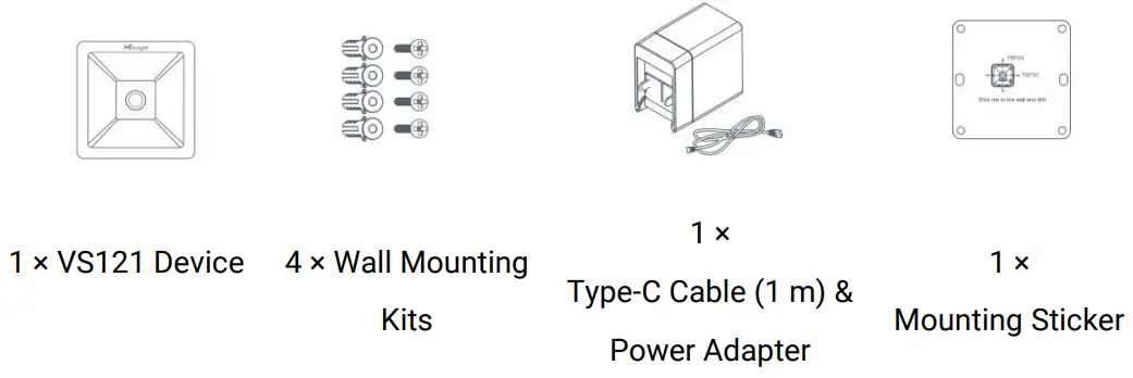

![]() If any of the above items is missing or damaged, please contact your sales representative.
If any of the above items is missing or damaged, please contact your sales representative.
2.2 Hardware Overview
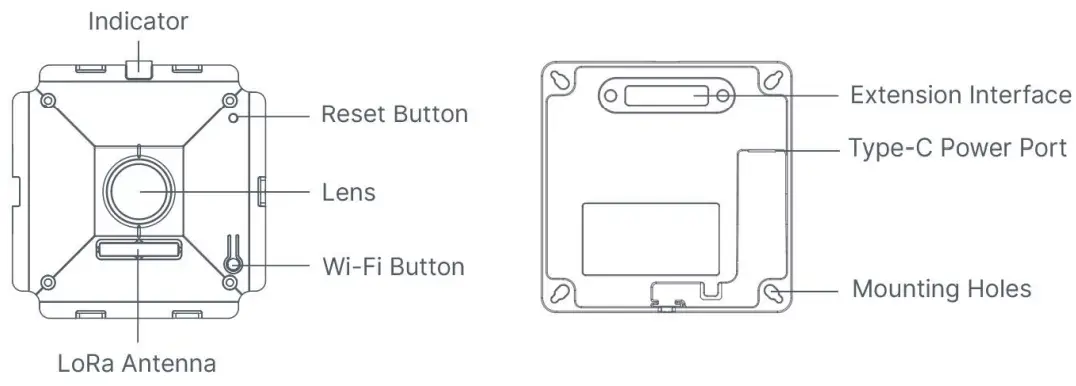
2.3 Buttons and LED Indicators
| Function | Action | LED Indication |
| Turn On/Off Wi-Fi | Press and hold the Wi-Fi button for more than 3 seconds. | Off → On |
| Press and hold the Wi-Fi button for more than 3 seconds. | On → Off | |
| Reset to Factory Default | Press and hold the reset button for more than 10 seconds. | Blinks 6 times. |
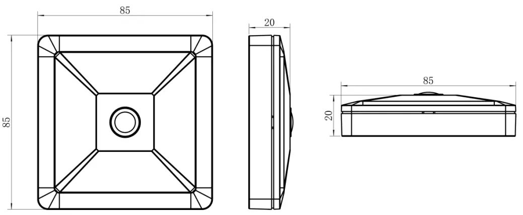
2.4 Dimensions (mm)
Access the Sensor
VS121 sensor provides user-friendly web GUI for configuration and users can access it via Wi-Fi connection. The recommended browsers are Internet Explorer, Firefox, Chrome, Microsoft Edge, Safari. The default IP of sensor is 192.168.1.1, and default SSID is Workplace Sensor_XXXXXX (can be found on the label).
3.1 Access without Plugin
Step 1: Power on the device.
Step 2: Enable the Wireless Network Connection on your computer and search for corresponding access point, then connect computer to this access point.
Step 3: Open the Browser and type 192.168.1.1 to access the web GUI.
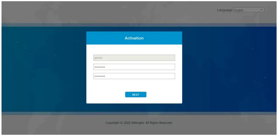
Step 4: Select the language.
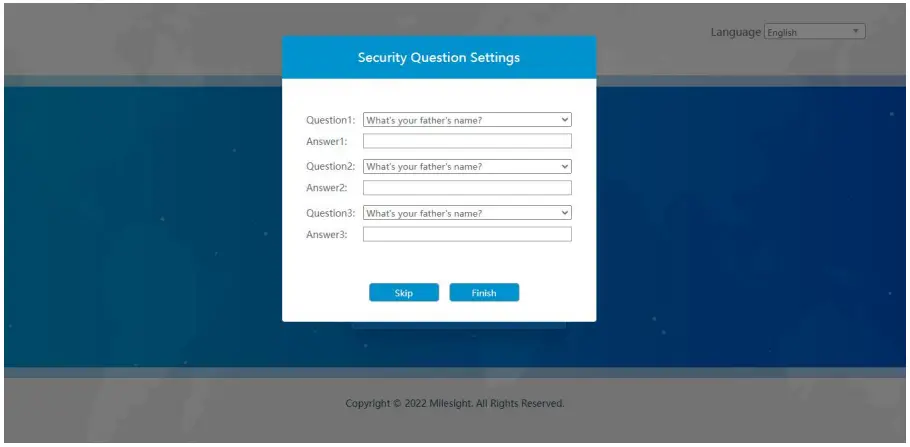
Step 5: Users need to set the password when using the sensor for the first time. And three security questions can also be set optionally. After configuration, use username (admin) and custom password to log in the sensor.
Note:
- Password must be 8 to 32 characters long, contains at least one number and one letter.
- You can click the “forgot password” in login page to reset the password by answering three security questions when you forget the password, if you set the security questions in advance.
3.2 Access with Plugin
For IE browser access, users need to install the MsActiveX firstly. You can refer the steps as follows:
Step1: Launch the IE browser and enter the IP address of the sensor;
Step2: Enter the user name and custom password and click “Login”;
Step3: At the first time to log in the device, the browser will prompt to install Controls, please click “Click here to download and install controls manually” as shown below;
Note:During installing the controls, please keep the browsers close.
Step4: Follow the prompts to install the Controls, when it`s finished, it will pop out a window as shown below. Please click “Finish” and refresh the browser, then you will see the video.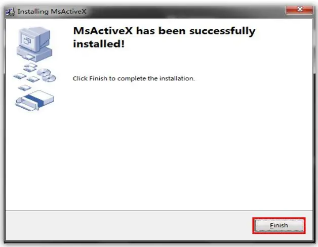
If IE9 or higher version browser is used, it is suggested that the web link should be added as a trusted site. See the instructions as follows:
Step1: Start the IE9 or higher version browser, and select “Tools”→ “Internet Options”;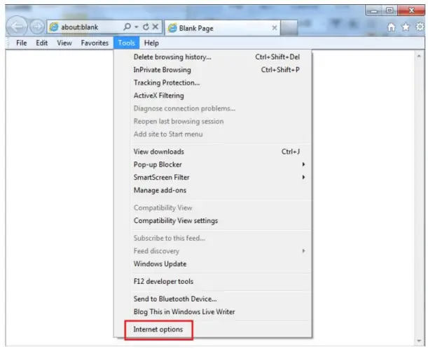
Step2: Select “Security” to “Trusted”;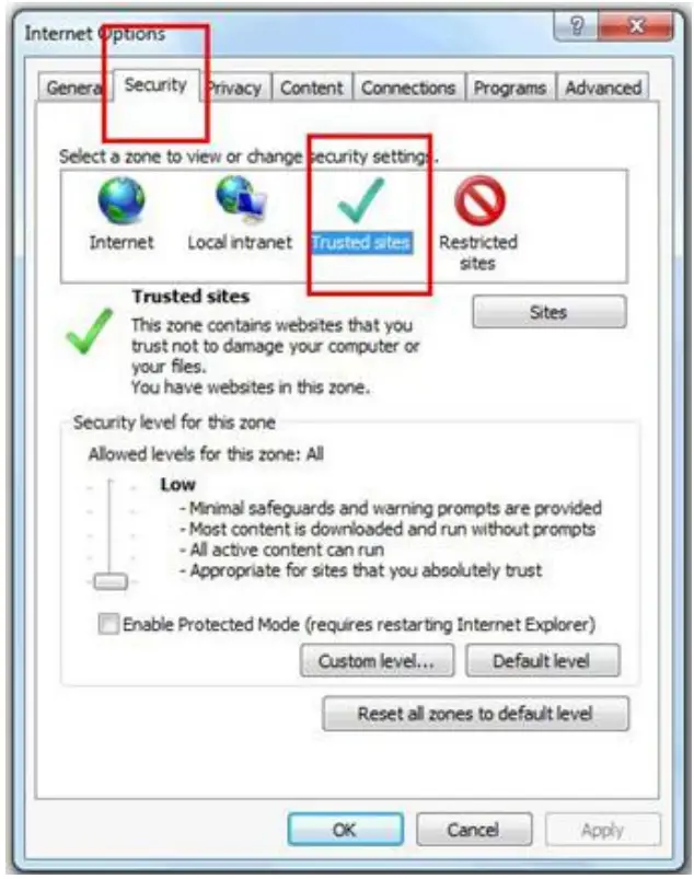
Step3: Enter the IP address of the device in the blank and click “Add”;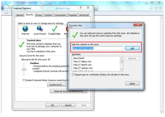
Step4: Enter the IP address. After logging on web GUI successfully, user is allowed to view live video.
Operation Guide
4.1 Live Video
After logging on to the device web GUI successfully, user is allowed to view live video as follows.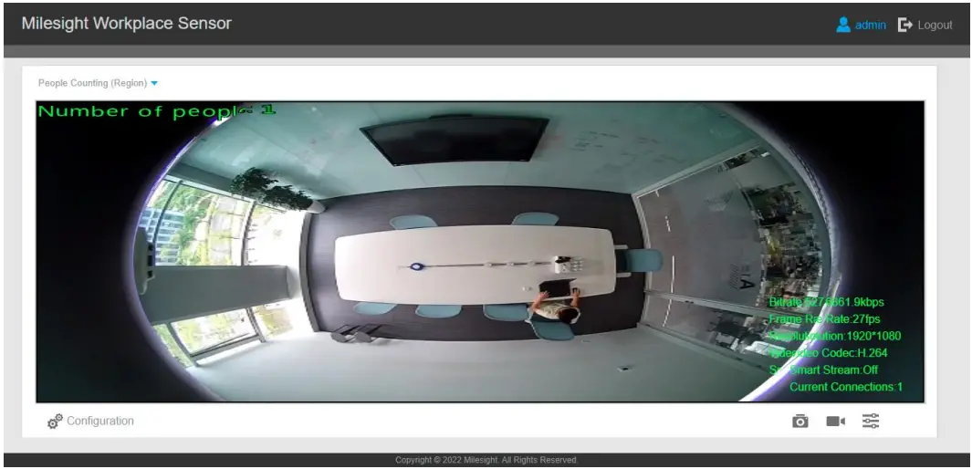
| Parameters | Description |
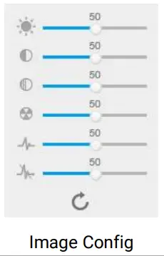 | Brightness: Adjust the Brightness of the scene |
| Contrast: Adjust the color and light contrast | |
| Saturation: Adjust the Saturation of the image. Higher Saturation makes | |
| colors appear more “pure” while lower one appears more “wash-out” | |
| Sharpness: Adjust the Sharpness of image. Higher Sharpness sharps the | |
| pixel boundary and makes the image looks “more clear” | |
| 2D DNR/3D DNR: Adjust the noise reduction level | |
| Default: Restore brightness, contrast and saturation to default settings | |
| Click to access the configuration page | |
 | People Counting (Region): show the mapped or non-mapped regions of people counting Line Crossing Counting: show the detection line and counting people it detected |
4.2 IoT
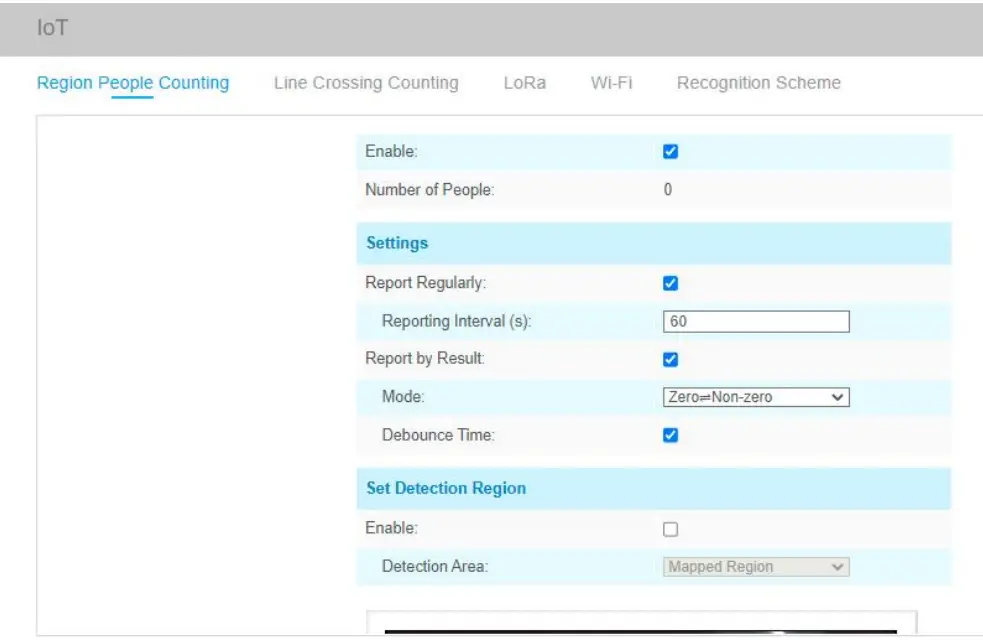
4.2.1 Region People Counting
Users can set the report settings and detection regions here.
| Parameters | Description |
| Enable | Enable or disable region people counting feature. |
| Number of People | Show current number of people. |
| Report Regularly | Report the current number of people according to reporting interval. Reporting Interval: 5-3600 s, default: 300 s |
| Report by Result | Report according to the following changes of people number result: l Zero to Non-zero/Non-zero to Zero l Once result changes |
| Debounce Time | VS121 will reduce the count value only when the people come out of the detection area for more than 2 s. |
| Enable | Enable the detection area customization feature. If disabled, the whole area will be the detection area. |
| Detection Area | Select the customized area as either mapped or except mapped area. You can draw the area in the below screen. 16 regions can be set at most. Mapped Region: Only people who are in the mapped region will be detected. Non-mapped Region: Only people who are not in the mapped region will be detected. Note: when drawing the area, right click the mouse can make the area closed. |
| Clear | Clear all areas you have drawn before. |
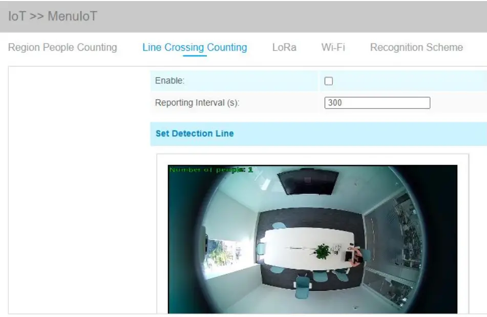
4.2.2 Line Crossing Counting
The sensor will count the number of people who crossed a defined virtual line, then upload the count value according to the reporting interval.
| Parameters | Description |
| Enable | Enable or disable line crossing counting feature. |
| Reporting Interval | Report the count value of people in/out during the reporting interval, the device will clean the previous values to re-count after reported, range: 5-3600 s, default: 300 s |
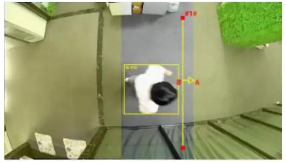
| Set Detection Line | The device allows to set up only one line. For the detection line, crossing along the direction of the arrow means “In” and the opposite is “Out”. |
| Clear Line | Clear the line you have drawn before. |
Note:
- The arrow direction of the detection line depends on your drawing direction.
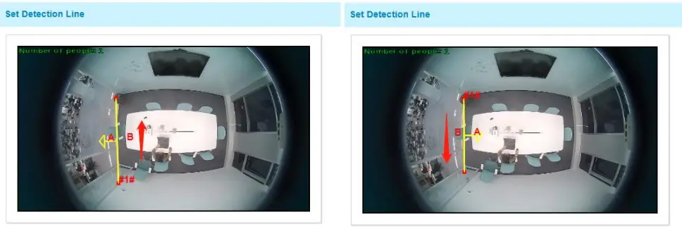
- Ensure the detection target can pass through the detection line completely. It’s recommended that draw the detection line perpendicular to the In/Out direction, and make the line on the center of detection area without other objects around.
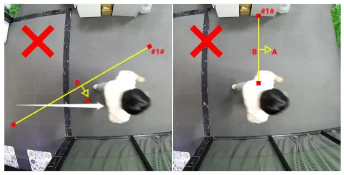
- A redundant identification area needed to be left on both sides of the detection line for the target. This is to ensure that the sensor has stable recognition and tracking of this target before it passes the detection line, which will make the detection and count more accurate.
4.2.3 LoRa
LoRa settings is used for configuring the transmission parameters in LoRaWAN® network or LoRa D2D network.
4.2.3.1 Basic Settings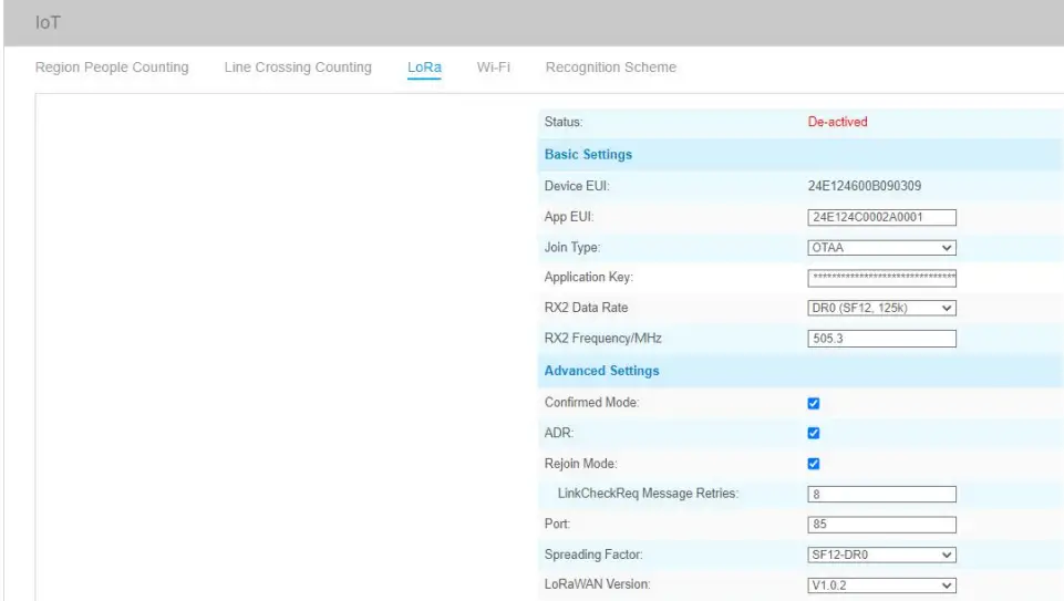
| Parameters | Description |
| Status | LoRaWAN® network status of this device. |
| Device EUI | Unique ID of the device which can also be found on the label. |
| App EUI | Default App EUI is 24E124C0002A0001. |
| Join Type | OTAA and ABP mode are available. |
| Application Key | Appkey for OTAA mode, default is 5572404C696E6B4C6F52613230313823. |
| Device Address | DevAddr for ABP mode, default is the 5th to 12th digits of SN. |
| Network Session Key | Nwkskey for ABP mode, default is 5572404C696E6B4C6F52613230313823. |
| Application Session Key | Appskey for ABP mode, default is 5572404C696E6B4C6F52613230313823. |
| RX2 Data Rate | RX2 data rate to receive downlinks or send LoRa D2D command. |
| RX2 Frequency/MHz | RX2 frequency to receive downlinks or send LoRa D2D command. |
| Confirmed Mode | If the device does not receive ACK packet from network server, it will resend data once. |
| ADR Mode | Allow network server to adjust data rate of the device. |
| Rejoin Mode | The device will send a specific number of LinkCheckReq MAC packets to the network server every 30 mins to validate connectivity; If there is no response, the device will re-join the network. |
| Application Port | The port used for sending and receiving data, default port is 85. |
| Spreading Factor | If ADR is disabled, the device will send data via this spreading factor. |
| LoRaWAN Version | V1.0.2, V1.0.3, V1.1.0 are available. |
| Region | Frequency plan of this device. |
| Channel | Enter the index to select the frequency channel. Examples: 1, 40: Enabling Channel 1 and Channel 40 1-40: Enabling Channel 1 to Channel 40 1-40, 60: Enabling Channel 1 to Channel 40 and Channel 60 All: Enabling all channels Null: Indicates that all channels are disabled |
Note:
- Please contact sales for device EUI list if there are many units.
- Please contact sales if you need random App keys before purchase.
- Only OTAA mode supports rejoin mode.
- For -868M model, default frequency is EU868; for -915M model, default frequency is AU915.
4.2.3.2 LoRa D2D Settings
LoRa D2D protocol is developed by Milesight and used for setting up transmission among Milesight LoRa devices without gateway. When the LoRa D2D setting is enabled, VS121 can work as a LoRa D2D controller for sending control commands to trigger LoRa D2D agent devices.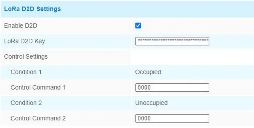
| Parameters | Description |
| Enable D2D | Enable or disable LoRa D2D feature. |
| LoRa D2D Key | Define a unique LoRa D2D key and this key is the same as the setting in LoRa D2D agent device. Default value: 5572404C696E6B4C6F52613230313823 |
| Condition | Occupied: when total people counter value is non-zero in detection area Unoccupied: when total people counter value is 0 in detection area |
| Control Command | Define a 2-byte hexadecimal control command (0x0000 to 0xffff). When the condition is meet, the device will send the control command to corresponding LoRa D2D agent devices. |
Note: When this feature is enabled, the control command from this device will not send to LoRaWAN® gateway.
4.2.4 Wi-Fi
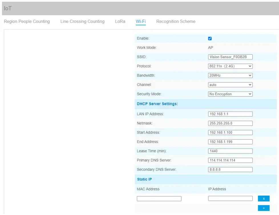
| Parameters | Description |
| Enabled | Enable Wi-Fi feature. |
| Work Mode | Work mode is fixed as AP and can not connect to other access point. |
| SSID | The unique name for this device Wi-Fi access point. |
| Protocol | 802.11b (2.4 GHz), 802.11g (2.4 GHz), 802.11n (2.4 GHz) are optional. |
| Bandwidth | 20 MHz or 40 MHz are optional. |
| Channel | Select the wireless channel. Auto, 1,…11 are optional. |
| Security Mode | No Encryption, WEP Open System, WEP Shared Key, WPA-PSK, WPA2-PSK and WPA-PSK/WPA2-PSK are optional. |
| DHCP Server Settings | LAN IP Address: IP address that used to access the web GUI of sensor. |
| Subnet mask: identify the subnet where the sensor is located. | |
| Start Address: define the beginning of IP address pool which assigns to DHCP clients. | |
| End Address: define the end of IP address pool which assigns to DHCP clients. | |
| Lease Time (min): the lease time on which DHCP client can use the IP address assigned by the sensor. | |
| Primary DNS Server: translate the domain name to IP address. | |
| Secondary DNS Server: backup DNS server. | |
| Static IP Settings | Add MAC address and static IP address if users need to add a static IP address to a specific computer. |
4.2.5 Recognition Scheme
You can select the recognition scheme for region people counting.
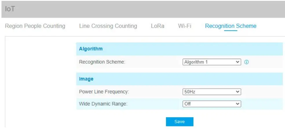
| Parameters | Description |
| Recognition Scheme | Select the recognition scheme based on your detection environment. Algorithm 1: Suitable for monitoring complex environments which have many objects, like office supplies (books, printers, lamps, etc.) Algorithm 2: Suitable for monitoring simple and clean environments like meeting rooms. |
| Image | Power Line Frequency: Select based on your power source frequency standard, 60 Hz and 50 Hz are available. |
| Wide Dynamic Range: This function which can capture and display both bright and dark areas in the same frame that enables details of objects in both bright and dark areas to be visible. It’s recommended to enable this function when the scene has a clear contrast between light and dark (such as a corridor). |
4.3 System
User
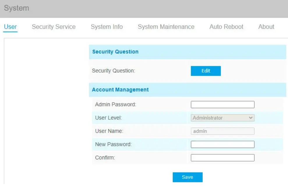
| Parameters | Description |
| Security Question | Click Edit button to set three security questions for your device. In case that you forget the password, you can click Forget Password button on login page to reset the password by answering three security questions correctly.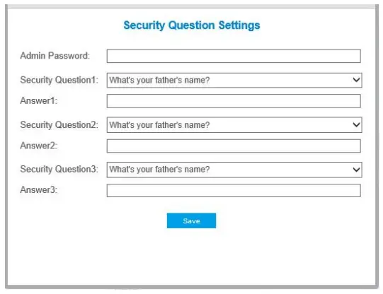 There are twelve default questions below, you can also customize the security questions. There are twelve default questions below, you can also customize the security questions.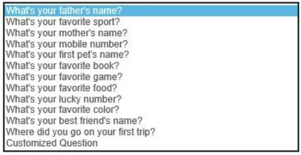 |
| Account Management | Admin Password: enter the correct admin password before adding an account. User Level: Set the privilege for the account. It’s fixed as Administrator. User Name: Input user name for creating an account. Password: Input password for the account. Confirm: Confirm the password. |
Security Service
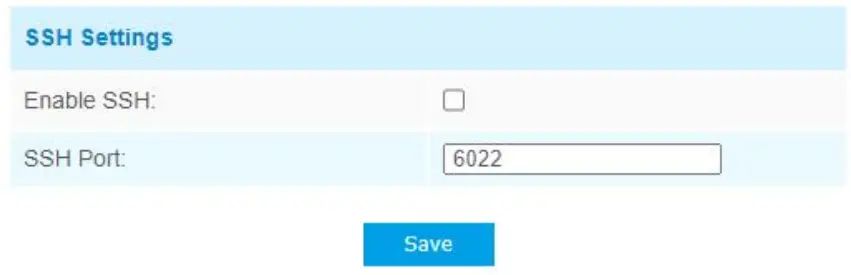
| Parameters | Description |
| Enable SSH | Enable SSH feature. |
| SSH Port | Set the port to access this sensor via SSH. |
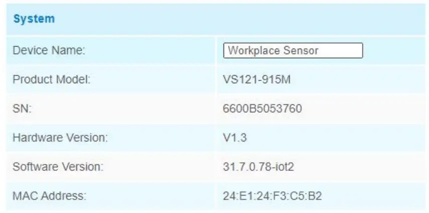
System Info
All information about the hardware and software can be checked on this page.
System Maintenance
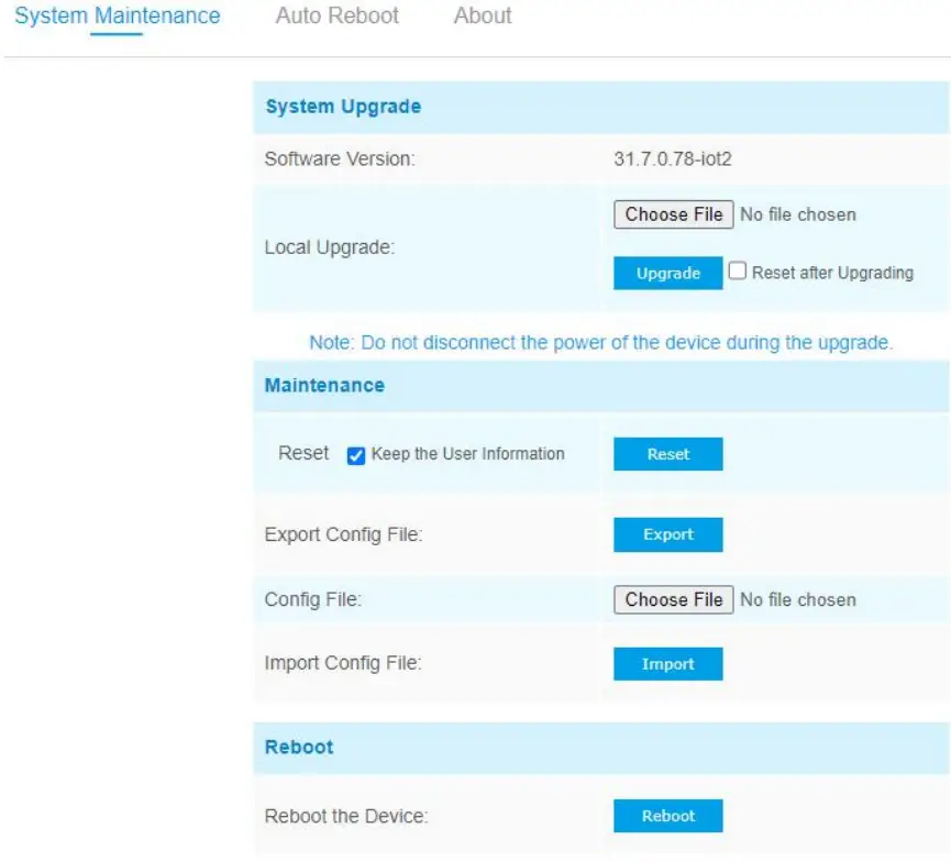
| Parameters | Description |
| System Upgrade | Software Version: The software version of the sensor. Local Upgrade: Click the Choose File button and select the upgrading file, then click the Upgrade button to upgrade. After the system reboots successfully, the update is done. You can check Reset after Upgrading to reset the device after upgrading it. Note: Do not disconnect the power of the device during the upgrade process. The device will be restarted to complete the upgrading. |
| Maintenance | Reset settings: Click Reset button to reset the device to factory default settings Keep the User Information: Check this option to keep the user information when resetting Export Config File: Export configuration file. Import Config File: Click the Choose File button and select the configuration file, click Import button to import configuration file. |
| Reboot | Restart the device immediately |
Auto Reboot
Set the date and time to enable device auto reboot, the device will reboot automatically according to the customized time in case that sensor overload after running a long time. Before configuration note that the date and time should correct.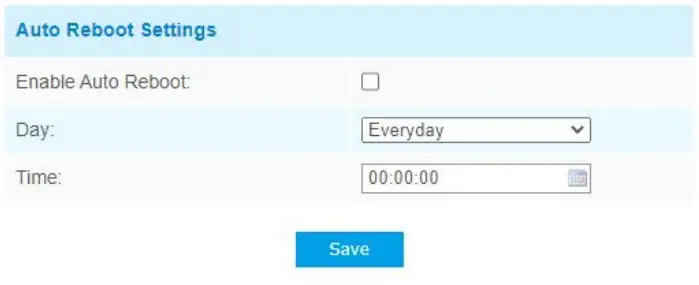
About
User can view some open source software licenses about the sensor by clicking the View Licenses button.
Mount the Sensor
To better utilize the advantages of AI algorithm, there are some important steps to follow :
5.1 Recommended Height for Certain Object
| Object | Height | Note |
| sitting object | >2.5m (8.2ft) | Commonly used for Region People Counting |
| standing object | >3m (9.8ft) (the optimum height is 3m) | Commonly used for Line Crossing Counting |
Recommended detection ranges for region people counting at different heights:
| Height | Recommended detection range |
| 2.5m | 3m*4m |
| 3m | 4.4m*5.7m |
| 3.5m | 4.9m*6.4m |
| 4m | 5.6m*7.4m |
5.2 Illuminance Requirements for AI Analysis
- Region People Counting
There is no requirement for illuminance, but we recommend enabling WDR function(Turn to page 17), which will make the image effect better. - Line Crossing Counting
- We recommend that the illuminance is greater than 50Lux.
- When the illuminance is between 20~50Lux, we recommend disabling WDR function.
- When the illuminance is >50Lux and the scene has a clear contrast between light and dark (such as a corridor), we recommend enabling WDR function.
To know the illuminance of the current scene, you must use an illuminance meter, or you can refer to the following common environmental illuminance values:
| place/environment | illuminance |
| Indoors at dusk | 10Lux |
| cloudy indoor | 5~50Lux |
| sunny indoor | 100~1000Lux |
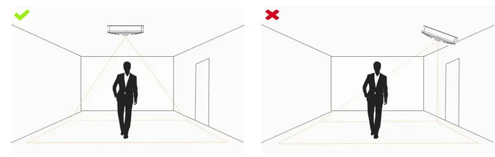
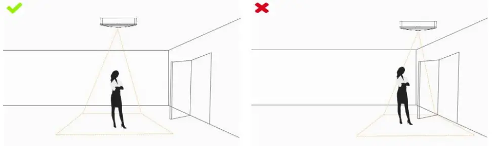
5.3 Recommended Installation for Line Crossing Counting
- Make sure the sensor is facing straight down, in line with the ceiling.
- Make sure there is sufficient white light on site.
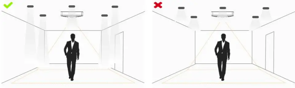
- Avoid getting very strong light, like sunlight.
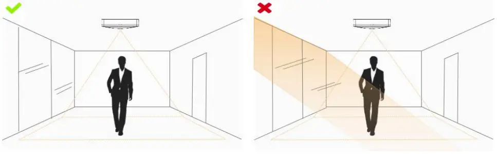
- Make sure there are no moving objects interfering in the counting area. For example, do not install the sensor too close to a door.
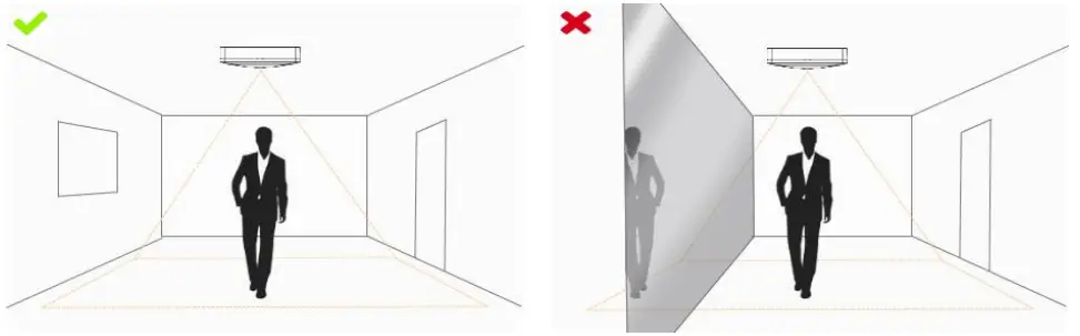
- Avoid installing the sensor near a mirror or avoid drawing the line to the mirror.
5.4 Factors Affecting Accuracy
- The color of hair or clothes is close to the floor color.
Reason: It will make it difficult for the algorithm to identify the correct object, thus affecting the accuracy. - The floor color and wall color are black.
Reason: The brightness of the scene will be reduced due to the absorption of light by black. - The contrast between light and dark in the scene is too strong.
Reason: It will cause the people to be backlight, which will affect the accuracy of the detection.
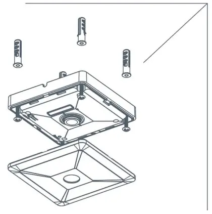
5.5 Ceiling Installation
Step 1: Ensure the thickness of ceiling is more than 30 mm, then attach the mounting sticker to the ceiling and drill 4 holes with a diameter of 6 mm.
Step 2: Fix the wall plugs into the ceiling holes.
Step 3: Remove the cover on the device, then fix the device to the wall plugs via mounting screws; remember to adjust the mounting direction according to the detection area requirement and direction sticker on the inner cover.
Step 4: Take the cover back to device; note that the Milesight Logo should be facing the LED indicator.
Device Payload
VS121 reports basic information only when joining the network and reports people counter according to reporting settings. All data are based on following format(HEX):
| Channel1 | Type1 | Data1 | Channel2 | Type2 | Data2 | Channel 3 | … |
| 1 Byte | 1 Byte | N Bytes | 1 Byte | 1 Byte | M Bytes | 1 Byte | … |
For decoder examples please find files on https://github.com/Milesight-IoT/SensorDecoders.
6.1 Uplink Data
VS121 report basic information of sensor whenever joining the network and the number of people according to settings.
| Channel | Type | Description |
| ff | 01(Protocol Version) | 01=> V1 |
| 08 (Device SN) | 12 digits | |
| 09 (Hardware Version) | 01 04 => V1.4 | |
| 1f (Software Version) | 1f 07 00 4b => V31.7.0.75 | |
| 4 | c9 (Region People Counter) | Byte 1: current total number of people Byte 2: how many mapped regions is customized Byte 3-4: indicate which mapped regions having detected people, 0 means no people detected, 1 means there are people detected in this mapped region |
| 5 | cc (Line Cross Counter) | Byte 1-2: in counter during the report interval Byte 3-4: out counter during the report interval |
| 6 | cd (Max People Counter) | Maximum number of people in detection area during the reporting interval of region people counting. Note: this value only update when you enable “Report Regularly” option. |
Example:
- Device information
ff0101 ff086600b0940976 ff090100 ff1f1f07004b Channel Type Value Channel Type Value ff 01
(Protocol
Version)01 (V1) ff 08
(Device SN)66 00 b0 94 09 76 Channel Type Value Channel Type Value ff 09
(Hardware version)0100 (V1.0) ff 1f (Software version) 1f 07 00 4b
(V31.7.0.75) - Region people counter regular uplink
04c9030800a1 06cd05 Channel Type Value 4 c9 (Region People Counter) Byte 1: 03 => There are 3 people totally now
Byte 2: 08 => there are 8 mapped regions
Byte 3-Byte 4: 00 a1=>1010 0001 there are people detected in region 1, 6 and 8Channel Type Value 6 cd (Max People Counter) 05 => during the reporting interval, the maximum number of people is 5 - Line cross counter
| 05cc02000100 | ||
| Channel | Type | Value |
| 5 | Cc (Line Crossing Counter) | In: 02 00 => 00 02 = 2 Out: 01 00 => 00 01 =1 |
6.2 Downlink Command
VS121 supports downlink commands to configure the device. Application port is 85 by default.
| Channel | Type | Description |
| ff | 10 (Reboot) | ff (Reserved) |
| 04 (Confirmed Mode) | 00: disable, 01: enable | |
| 05 (Change LoRa Channel Mask) | Byte 1: Channel index range 01: 0-15 02: 16-31 03: 32-47 04: 48-63 05: 64-79 06: 80-95 Byte 2-3: indicate disable or enable via every bit, 0=disable, 1=enable | |
| 40 (ADR) | 00: disable, 01: enable | |
| 41 (Configure Application Port) | 1 Byte, default is 85 | |
| 42 (Wi-Fi) | 00: disable, 01: enable | |
| 50 (Region People Counting) | 00: disable, 01: enable | |
| 43 (Region People Counting Report Regularly) | 00: disable, 01: enable | |
| 44 (Region People Counting Report by Result) | 00: disable, 01: enable | |
| 45 ( Report by Result Mode) | 00: Zero and Non-zero 01: Once result changes | |
| 48 (Line Crossing Counting) | 00: disable, 01: enable |
Note:after changing LoRa setting, the device will re-join the network.
Example:
- Disable the Wi-Fi.
ff4200 Channel Type Value ff 42 (Wi-Fi) 00: disable - Set AU915 or US915 channel mask as 8-15.
ff0501ff00 ff05020000 ff05030000 ff05040000 ff05050000 Channel Type Value ff 05
(Set Channel Mask)01: Channel index 0-15, ff00 => 8-15 is enabled
02-05: Channel index 16-79, 0000 => all disabled - Reboot the device.
| ff10ff | ||
| Channel | Type | Value |
| ff | 10 (Reboot) | ff (Reserved) |
![]() 14 rue Edouard Petit F42000 Saint-Etienne
14 rue Edouard Petit F42000 Saint-Etienne
Tel: +33 (0) 477 92 03 56
Fax: +33 (0) 477 92 03 57
Remy GUEDOT Gsm: +33 (0) 662 80 65 57 [email protected]
Olivier BENAS Gsm: +33 (0) 666 84 26 2E [email protected]
www.rg2i.fr
Interfaces pour I’nformatique industrielle
ATTENTION – NOUVELLE ADRESSE


