Milesight VS121 AI Workplace Sensor User Guide
Safety Precautions
Milesight will not shoulder responsibility for any loss or damage resulting from not following the instructions of this operating guide.
- The device must not be disassembled or remodeled in any way.
- To avoid the risk of fire and electric shock, do keep the product away from rain and moisture before installation.
- Do not place the device where the temperature is below/above the operating range.
- Do not touch components that may be hot.
- The device must never be subjected to shocks or impacts.
- Make sure the device is firmly fixed when installing.
- Make sure the plug is firmly inserted into the power socket.
- Do not expose the device to where laser beam equipment is used.
- Use a soft, dry cloth to clean the lens of the device. Stubborn stains can be removed using a cloth dampened with a small quantity of detergent solution, then wipe them dry.
Declaration of Conformity
VS121 is in conformity with the essential requirements and other relevant provisions of the CE, FCC, and RoHS.
Copyright © 2011-2022 Milesight. All rights reserved.
All information in this guide is protected by copyright law. Whereby, no organization or individual shall copy or reproduce the whole or part of this user guide by any means without written authorization from Xiamen Milesight IoT Co., Ltd.
 For assistance, please contact
Milesight technical support:
Email: iot.[email protected]
Tel: 86-592-5085280
Fax: 86-592-5023065
Address: Building C09, Software Park
Phase III, Xiamen 361024, China
Revision History
| Date | Doc Version | Description |
| Apr. 26, 2021 | V 1.0 | Initial version |
| Jan. 18, 2022 | V 1.1 | 1. Support line crossing counting feature; 2. Support LoRa D2D feature; 3. Support people counting debounce; 4. Support uploading max number of people; 5. Support downlink control. |
| Apr. 8, 2022 | V 1.2 | 1. Milesight LOGO update 2. Support recognition scheme selection |
Product Introduction
Overview
VS121, based on Artificial Intelligence (AI) technology, is an AI workplace sensor designed to monitor occupancy & utilization in the modern workspace, which can reach up to 95% recognition rate. With the ability to sense from up to 78m, fewer sensors are needed to cover the same area, decreasing the deployment costs for users. Only counter values are transmitted over LoRaWAN® 2 network to prevent privacy concerns. VS121 is equipped with Wi-Fi for easy configuration without any tools.
Sensor data are transmitted in real-time using the standard LoRaWAN® protocol. LoRaWAN® enables encrypted radio transmissions over long distances while consuming very little power. The user can obtain sensor data and view the trend of data change through the user’s own network server.
Key Features
- The recognition rate is up to 95% based on advanced AI identification and analysis technology and wide detection range
- Support to map up to 12 custom regions
- No image data is collected, free from privacy concerns
- Equipped with Wi-Fi for web GUI configuration
- Function well with standard LoRaWAN® gateways and network servers
Hardware Introduction
Packing List
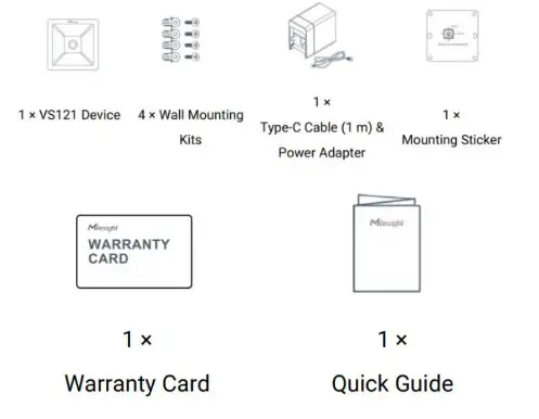
![]() If any of the above items is missing or damaged, please contact your sales representative.
If any of the above items is missing or damaged, please contact your sales representative.
Hardware Overview
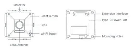
| Function | Action | LED Indication |
| Turn On/Off Wi-Fi | Press and hold the Wi-Fi button for more than 3 seconds. | Off → On |
| Press and hold the Wi-Fi button for more than 3 seconds. | On → Off | |
| Reset to Factory Default | Press and hold the reset button for more than 10 seconds. | Blinks 6 times. |
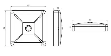
Dimensions (mm)
Access the Sensor
VS121 sensor provides a user-friendly web GUI for configuration and users can access it via a Wi-Fi connection. The recommended browsers are Internet Explorer, Firefox, Chrome, Microsoft Edge, and Safari. The default IP of the sensor is 192.168.1.1, and the default SSID is Vision Sensor_XXXXXX (can be found on the label).
Access without Plugin
Step 1: Power on the device.
Step 2: Enable the Wireless Network Connection on your computer and search for corresponding the access point, then connect the computer to this access point.
Step 3: Open the Browser and type 192.168.1.1 to access the web GUI.
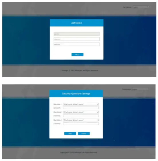
Step 4: Select the language.
Step 5: Users need to set the password when using the sensor for the first time. And three security questions can also be set optionally. After configuration, use a username (admin) and custom password to log in to the sensor.
Note:
- Password must be 8 to 32 characters long and contains at least one number and one letter.
- You can click the “forgot password” on a login page to reset the password by answering three security questions when you forget the password if you set the security questions in advance.
Access with Plugin
For IE browser access, users need to install the MsActiveX first. You can refer to the steps as follows:
Step1: Launch the IE browser and enter the IP address of the sensor;
Step2: Enter the user name and custom password and click “Login”;
Step3: At the first time to log in to the device, the browser will prompt to install Controls, please click “Click here to download and install controls manually” as shown below;

Note: During installing the controls, please keep the browsers close.
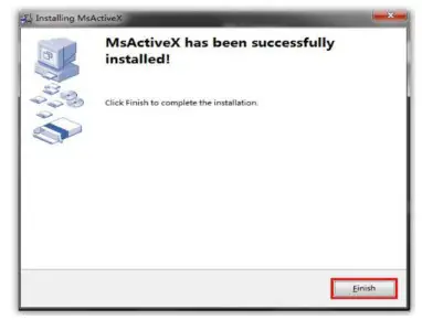
Step4: Follow the prompts to install the Controls, when it`s finished, it will pop out a window as shown below. Please click “Finish” and refresh the browser, then you will see the video.
If IE9 or a higher version browser is used, it is suggested that the web link should be added as a trusted site. See the instructions as follows:
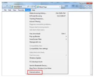
Step1: Start the IE9 or higher version browser, and select “Tools”→ “Internet Options”;
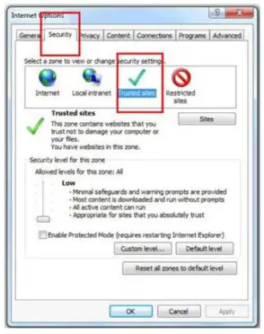
Step2: Select “Security” to “Trusted”;
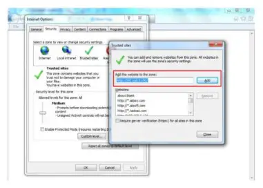
Step3: Enter the IP address of the device in the blank and click “Add”;
Step4: Enter the IP address. After logging on to web GUI successfully, the user is allowed to view live video.
Operation Guide
Live Video
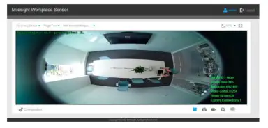
After logging on to the device web GUI successfully, the user is allowed to view the live video as follows.
| Parameters | Description | |
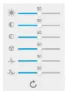 Image Config | Brightness: Adjust the brightness of the scene | |
| Contrast Adjust the color and light contrast | ||
| Saturation: Adjust the Saturation of the image. Higher Saturation makes colors appear more ‘pure’ while lower one appears more awash-out” | ||
| Sharpness: Adjust the Sharpness of the image. Higher Sharpness sharps the pixel boundary and makes the image looks clear | ||
| 2D DNR/3D DNR: Adjust the noise reduction level | ||
| Default Restore brightness, contrast, and saturation to default settings | ||
 | Click to access the configuration page | |
 | People Counting (Region): show the mapped or non-mapped regions of people counting Line Crossing Counting: show the detection line and people it detected Hide Detection Region: hide the people detection region | |
Window size  | Click to display images at a window size | |
Real size  | Click to display images at a real size | |
 | Click to display images at full-screen | |
| Full Screen | Start/Stop live view | |
 | Full Screen | |
 | When enabled, you can zoom in on a specific area of the video image with your mouse wheel | |
IoT
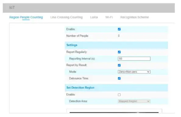
Region People Counting
Users can set the report settings and detection regions here.
| Parameters | Description |
| Enable | Enable or disable the region people counting feature. |
| Number of People | Show a current number of people. |
| Report Regularly | Report the current number of people according to reporting interval. Reporting Interval: 5-3600s, default: 300 s |
| Report by Result | Report according to following people number results: • Zero and Non-zero • Once result in changes |
| Debounce Time | VS121 will reduce the count value to only the people who come out of the detection area for more than 2 s. |
| Enable | Enable the detection area customization feature. If disabled, the whole area will be the detection area. |
| Detection Area | Select the customized area as either mapped or except mapped area. You can draw the area in the below screen. 12 regions can be set at most. Mapped Region: Only people who are in the mapped region will be detected. Non-mapped Region: Only people who are not in the mapped region will be detected. |
| Clear | Clear all areas you have drawn before. |
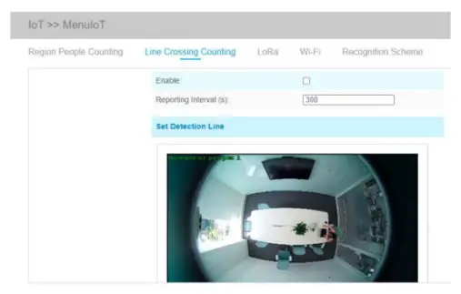
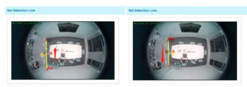
Line Crossing Counting
When the sensor detected the people crossing a defined virtual line, it will upload the counting.
| Parameters | Description |
| Enable | Enable or disable the line crossing counting feature. |
| Reporting Interval | Report the count value of people in/out during the reporting interval, the device will clean the previous values to re-count after reported, range: 5-3600 s, default: 300 s |
| Set Detection Line | The device allows to set up only one line. For the detection line, crossing along the direction of the arrow means “In” and the opposite is “Out”. |
| Clear | Clear the line you have drawn before. |
Note: the arrow direction of the detection line depends on the direction of your draw.
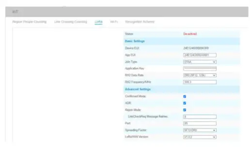
Lora
LoRa settings are used for configuring the transmission parameters in the LoRaWAN® network or LoRa D2D network.
Basic Settings
| Parameters | Description |
| Status | LoRaWAN® network status of this device. |
| Device EUI | The unique ID of the device can also be found on the label. |
| App EUI | Default App EUI is 24E124C0002A0001. |
| Join Type | OTAA and ABP modes are available. |
| Application Key | Appkey for OTAA mode, default is 5572404C696E6B4C6F52613230313823. |
| Device Address | Devendra for ABP mode, the default is the 5th to 12th digits of SN. |
| Network Session | Nwkskey for ABP mode, default is 5572404C696E6B4C6F52613230313823. |
| Key | |
| Application Session Key | Appskey for ABP mode, default is 5572404C696E6B4C6F52613230313823. |
| RX2 Data Rate | RX2 data rate to receive downlinks or send LoRa D2D command. |
| RX2 Frequency/MHz | RX2 frequency to receive downlinks or send LoRa D2D command. |
| Confirmed Mode | If the device does not receive an ACK packet from a network server, it will resend data 3 times at most. |
| ADR Mode | Allow the network server to adjust the data rate of the device. |
| Rejoin Mode | Reporting interval s 30 mins: the device will send specific mounts of LoRa MAC packets to check connection status every 30 mins; If no reply after specific packets, the device will re-join. Reporting interval > 30 mins: the device will send specific mounts of LoRaMAC packets to check connection status every reporting interval; If no reply after specific packets, the device will re-join. |
| Application Port The port used for sending and receiving data, the default port is 85. | |
| Spreading Factor | If ADR is disabled, the device will send data via this spreading factor. |
| LoRaWAN Version | V1.0.2, V1.0.3, and V1.1.0 are available. |
| Region | The frequency plan of this device. |
| Channel | Enter the index to select the frequency channel. Examples: 1,40: Enabling Channel 1 and Channel 40 1-40: Enabling Channel 1 to Channel 40 1-40, 60: Enabling Channel 1 to Channel 40 and Channel 60 All: Enabling all channels Null: Indicates that all channels are disabled |
Note:
- Please contact sales for device EUI list if there are many units.
- Please contact sales if you need random App keys before purchase.
- Only OTAA mode supports rejoin mode.
- For the -868M model, the default frequency is EU868; for the -915M model, the default frequency is AU915.
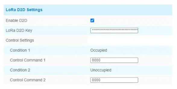
Lora D2D Settings
Lora D2D protocol is developed by Milesight and used for setting up transmission among Milesight LoRa devices without a gateway. When the LoRa D2D setting is enabled, VS121 can work as a LoRa D2D controller for sending control commands to trigger LoRa D2D agent devices.
| Parameters | Description |
| Enable D2D | Enable or disable the LoRa D2D feature. |
| Lora D2D Key | Define a unique LoRa D2D key and this key is the same as the setting in the LoRa D2D agent device. Default value: 5572404C696E6B4C6F52613230313823 |
| Condition | Occupied: when the total people counter value is non-zero in the detection area Unoccupied: when the total people counter value is 0 in the detection area |
| Control Command | Define a 2-byte hexadecimal control command (0x0000 to 0xffff). When the condition is met, the device will send the control command to corresponding LoRa D2D agent devices. |
Note: When this feature is enabled, the control command from this device will not send to the LoRaWAN® gateway.
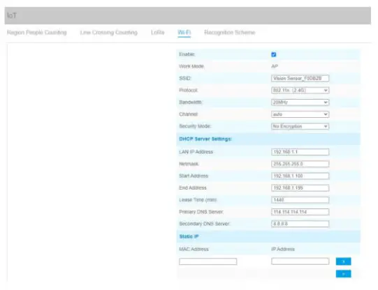
Wi-Fi
| Parameters | Description |
| Enabled | Enable the Wi-Fi feature. |
| Work Mode | Work mode is fixed as AP and can not connect to another access point. |
| SID | The unique name for this device is Wi-Fi access point. |
| Protocol | 802.11b (2.4 GHz), 802.11g (2.4 GHz), 802.11n (2.4 GHz) are optional. |
| Bandwidth | 20 MHz or 40 MHz are optional. |
| Channel | Select the wireless channel. Auto, 1,…11 are optional. |
| Security Mode | No Encryption, WEP Open System, WEP Shared Key, WPA-PSK, WPA2-PSK, and WPA-PSK/WPA2-PSK are optional. |
| DHCP Server Settings | LAN IP Address: the IP address that is used to access the web GUI of the sensor. |
| Subnet mask: identify the subnet where the sensor is located. | |
| Start Address: define the beginning of the IP address pool which assigns to DHCP clients. | |
| End Address: define the end of the IP address pool which assigns to DHCP clients. | |
| Lease Time (min): the lease time on which DHCP client can use the IP address assigned by the sensor. | |
| Primary DNS Server: translate the domain name to IP address. |
| Secondary DNS Server: backup DNS server. | |
| Static IP Settings | Add MAC address and static IP address if users need to add a static IP address |
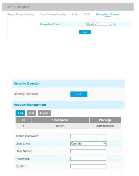
Recognition Scheme
You can select the recognition scheme for region people counting.
Advanced Settings
Security
User
| Parameters | Description |
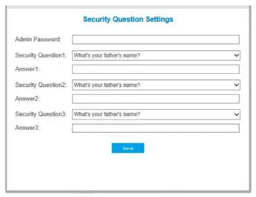
| Security Question | Click the Edit button to set three security questions for your device. In case that you forget the password, you can click Forget Password button on the login page to reset the password by answering three security questions correctly.
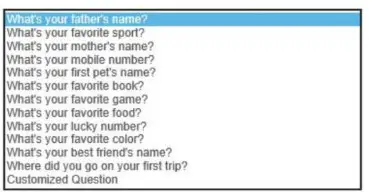
There are twelve default questions below, you can also customize the security questions.
|
| Account Management | Click Add button, it will display the Account Management page. Users can add an account by entering Admin Password, User Level, User Name, New Password, Confirm, and edit user privilege by clicking. The added account will be displayed in the account list. Users can add 20 accounts at most. Admin Password: enter the correct admin password before adding an account. User Level: Set the privilege for the account. User Name: The input user name for creating an account. Password: Input the password for the account. Confirm: Confirm the password. You can edit and delete the account in the account list under the admin account. For the default admin account, you can only change the password, and it cannot be deleted. |
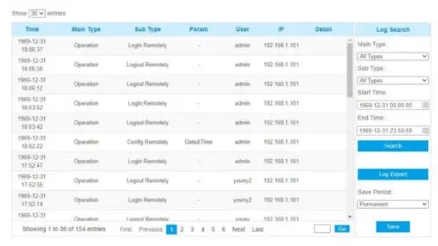
Logs
The logs contain information about the time and IP that has accessed the web GUI.
| Parameters | Description |
| Main Type | Select main log types |
| Sub Type | On the premise of the main type has been selected, select the sub type to narrow the range of logs |
| Start Time | The time the log starts |
| End Time | The time the log ends |
| Log Export | Export the logs |
| Save Period | Set the period of log saving, there are eight options to choose from: Permanent and 30/60/120/180/240/300/360 Days |
| Go | Input the number of logs’ page |
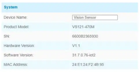
System
All information about the hardware and software can be checked on this page.
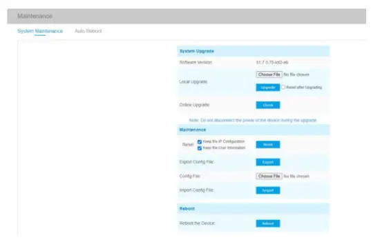
Maintenance
System Maintenance
| Parameters | Description |
| System Upgrade | Software Version: The software version of the sensor. Local Upgrade: Click the Choose File button and select the upgrading file, then click the Upgrade button to upgrade. After the system reboots successfully, the update is done. You can check Reset after Upgrading to reset the device after upgrading it. Note: Do not disconnect the power of the device during the upgrade process. The device will be restarted to complete the upgrade. |
| Maintenance | Reset settings: Click the Reset button to reset the device to factory default settings Keep the IP Configuration: Check this option to keep the IP configuration when resetting Keep the User Information: Check this option to keep the user information when resetting Export Config File: Export configuration file. Import Config File: Click the Choose File button and select the configuration file, click the Import button to import the configuration file. |
| Reboot | Restart the device immediately |
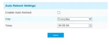
Auto Reboot
Set the date and time to enable the device auto reboot, the device will reboot automatically according to the customized time in case of that sensor overloads after running a long time. Before configuration note that the date and time should be correct.
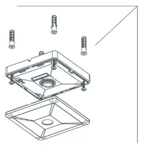
Installation
Step 1: Ensure the thickness of the ceiling is more than 30 mm, then attach the mounting sticker to the ceiling and drill 4 holes with a diameter of 6 mm.
Step 2: Fix the wall plugs into the ceiling holes.
Step 3: Remove the cover on the device, then fix the device to the wall plugs via mounting screws; remember to adjust the mounting direction according to the detection area requirement and direction sticker on the inner cover.
Step 4: Take the cover back to the device; note that the Milesight Logo should be facing the LED indicator.
Device Payload
VS121 reports basic information only when joining the network and reports people counter according to reporting settings. All data are based on the following format(HEX):
| Channel1 | Type1 | Data1 | Channel2 | Type2 | Data2 | Channel 3 | … |
| 1 Byte | 1 Byte | N Bytes | 1 Byte | 1 Byte | M Bytes | 1 Byte | … |
For decoder examples please find files on https://github.com/Milesight-IoT/SensorDecoders.
Uplink Data
VS121 reports basic information of the sensor whenever joining the network and the number of people according to settings.
| Channel | Type | Description |
| ff | 01(Protocol Version) | 01=> V1 |
| 08 (Device SN) | 12 digits | |
| 09 (Hardware Version) | 01 04 => V1.4 | |
| 1f (Software Version) | lf 07 00 4b => V31.7.0.75 | |
| 04 | c9 (Region People Counter) | Byte 1: current total number of people Byte 2: how many mapped regions is customized Byte 3-4: indicate which mapped regions having detected people, 0 means no people detected, 1 means there are people detected in this mapped region |
| 05 | cc (Line Cross Counter) | Byte 1-2: in counter during the report interval Byte 3-4: out counter during the report interval |
| 06 | cd (Max People Counter) | A maximum number of people in the detection area during the reporting interval of region people counting. Note: this value only updates when you enable the “Report Regularly” option. |
Example:
- Device information
ff0101 ff086600b0940976 ff090100 ff1f1f07004b Channel Type Value Channel Type Value ff 01(Protocol Version) 01 (V1) ff 08 (Device SN) 66 00 b0 94 09 76 ff 09 (Hardware version) 0100 (V1.0) ff if (Software version) 1f 07 00 4b(V31.7.0.75) - Region people counter regular uplink
04c9030800a1 06cd05 Channel Type Value 04 c9 (Region People Counter) Byte 1: 03 => There are 3 people totally now
Byte 2: 08 => there are 8 mapped regions
Byte 3-Byte 4: 00 a1=>1010 0001
there are people detected in regions 1, 6 and 8Channel Type Value 06 cd (Max People Counter) 05 => during the reporting interval, the maximum number of people is 5 - Line cross counter
05cc02000100 Channel Type Value 5 Cc (Line Crossing Counter) In: 02 00 => 00 02 = 2
Out: 01 00 => 00 01 =1
Downlink Command
VS121 supports downlink commands to configure the device. The application port is 85 by default.
| Channel | Type | Description |
| ff | 10 (Reboot) | ff (Reserved) |
| 04 (Confirmed Mode) | 00: disable, 01: enable | |
| 05 (Change LoRa Channel Mask) | Byte 1: Channel index range 01: 0-15 02:16-31 3:32-47 4:48-63 5:64-79 6:80-95 Byte 2-3: indicate disable or enable via every bit, 0=disable, 1=enable |
| 40 (ADR) | 00: disable, 01: enable | |
| 41 (Configure Application Port) | 1 Byte, default is 85 | |
| 42 (Wi-Fi) | 00: disable, 01: enable | |
| 50 (Region People Counting) | 00: disable, 01: enable | |
| 43 (Region People Counting Report Regularly) | 00: disable, 01: enable | |
| 44 (Region People Counting Report by Result) | 00: disable, 01: enable | |
| 45 ( Report by Result Mode) | 00: Zero and Non-zero 01: Once the result changes | |
| 48 (Line Crossing Counting) | 00: disable, 01: enable |
Note: after changing the LoRa setting, the device will re-join the network.
Example:
- Disable the Wi-Fi.
ff4200 Channel Type Value ff 42 (Wi-Fi) 00: disable - Set AU915 or US915 channel mask as 8-15.
ff0501ff00 ff05020000 ff05030000 ff05040000 ff05050000 Channel Type Value ff 05 (Set Channel Mask) 01: Channel index 0-15, ff00 => 8-15 is enabled
02-05: Channel index 16-79, 0000 => all disabled - Reboot the device.
ff10ff Channel Type Value ff 10 (Reboot) ff (Reserved)


