![]() 62DA,DB,DC,DD,DE,DF07-38
62DA,DB,DC,DD,DE,DF07-38
Roof Curb Accessory
Installation Instructions
Part Numbers: CRRFCURB053A01, CRRFCURB054A01, CRRFCURB055A01, CRRFCURB056A01
PACKAGE USAGE
| UNIT 62DA,DB,DC,DD,DE,DF | PART NUMBER | NOMINAL HEIGHT (in.) |
| 07-20 | CRRFCURB053A01 | 14 |
| CRRFCURB054A01 | 24 | |
| 22-38 | CRRFCURB055A01 | 14 |
| CRRFCURB056A01 | 24 |
PACKAGE CONTENTS
| ITEM | QUANTITY |
| Curb Frame Sides | 2 |
| Curb Frame Ends | 2 |
| Duct Supports | 3 |
| Utility Channel | 1 |
| Equipment Supports | 2 |
| Hardware Bag | 1 |
| Gasket | 1 |
SAFETY CONSIDERATIONS
Installation and servicing of air-conditioning equipment can be hazardous due to system pressure and electrical components. Only trained and qualified service personnel should
install, repair, or service air-conditioning equipment.
| PART NO. CRRFCURB | DIMENSIONS (in.) | |
| A | B | |
| 053A01 | 14 | 8 1/2 |
| 054A01 | 24 | 81/2 |
Untrained personnel can perform the basic maintenance functions of replacing filters. All other operations should be performed by trained service personnel. When working on air-conditioning equipment, observe precautions in the literature, tags and labels attached to the unit, and other safety precautions that may apply.
INSTALLATION
![]() WARNING
WARNING
To prevent injuries and brain damage, do not leave the roof openings uncovered. If the installation is not completed immediately after the roof opening is cut and framed, provide an adequate temporary cover for the roof opening.
- Before installing the roof curb, ensure that curb is located so that proper clearances are maintained. Check unit nameplate or unit installation instructions for correct clearances.
- Cut hole in the roof for duct openings. See Fig. 1 and 2 for dimensions. It is not necessary to cut out the entire area of the roof curb. If utility connections are to be made through the curb, cut out the access space near the location of the utility plate connector.

- Fig. 1 — Roof Curb Details (CRRFCURB053A01 and CRRFCURB054A01)

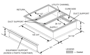
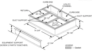
Fig. 2 — Roof Curb Details (CRRFCURB055A01 and CRRFCURB056A01)
3. Frame the roof opening to provide proper and adequate structural support.
4. Assemble the perimeter of the roof curb. Bring together curbside and end. Insert the tabs into the slots as shown in Fig. 3. Press the pieces together so that the tab is locked into place. It may be necessary to lightly hammer or to step on the side to lock the parts in place. Repeat for the other curbside and end until the outer perimeter is assembled.
5. Screw the utility channel into the curbside as shown in Fig. 1 and 2.
6. Square up the roof curb (see Fig. 4) and position over the roof opening. Level the curb to maintain leveling tolerance specified in unit instructions. Secure the roof curb to the roof structure by welding or screwing in place.
7. Install the duct supports as shown in Fig. 1 and 2.
8. Install ductwork into the curb. The duct will hang from the top of the curb.
IMPORTANT: Ductwork must be installed before the unit is placed on the roof curb.
9. Screw the 2 equipment support frames together to form the condenser end equipment support.
10. Locate equipment support per Fig. 1 or 2 and attach to the roof structure by welding or screwing in place.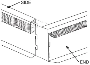
Fig. 3 — Corner Bracket Details
11. Place gasket around the outer perimeter of the curb and around duct openings, as shown in Fig. 1, 2, and 5.
12. Weatherproof the roof curb, per Fig. 5 recommendations or using the specific job requirements.![]() CAUTION
CAUTION
Do not slide the unit to position it when it is sitting on the curb.
Curb gasketing material may be damaged and leaks may result.
FRAME IS SQUARE WHEN LENGTH FROM CORNER A TO B EQUAL TO LENGTH FROM CORNER C TO D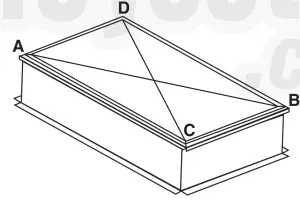
Fig. 4 — Squaring Frame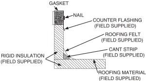
Fig. 5 — Gasket and Weatherproofing Detail
The manufacturer reserves the right to discontinue or change at any time, specifications, or designs without notice and without incurring obligations.
Catalog No. 04-53620015-01
Printed in the U.S.A.
Form 62D-5SI
Pg 2
3-11
Replaces: 62D-2SI


