![]()
Installation Instructions
LP Conversion Kit
Precedent™ Packaged Rooftop Units
6 to 25 Tons Two-Stage
Model Number: Used With:
FIALPKT002* YSJ(072-150)A**(0,A)(L,M,H)
FIALPKT003* YSJ(180-300)A**(0,A)(L,M,H)
FIALPKT002* Precedent Packaged Rooftop Units
![]() SAFETY WARNING
SAFETY WARNING
Only qualified personnel should install and service the equipment. The installation, starting up, and servicing of heating, ventilating, and air-conditioning equipment can be hazardous and requires specific knowledge and training. Improperly installed, adjusted or altered equipment by an unqualified person could result in death or serious injury.
When working on the equipment, observe all precautions in the literature and on the tags, stickers, and labels that are attached to the equipment.
Introduction
Read this manual thoroughly before operating or servicing this unit.
Warnings, Cautions, and Notices
Safety advisories appear throughout this manual as required. Your personal safety and the proper operation of this machine depend upon the strict observance of these precautions.
The three types of advisories are defined as follows:![]() WARNING
WARNING
Indicates a potentially hazardous situation which, if not avoided, could result in death or serious injury.![]() CAUTION
CAUTION
Indicates a potentially hazardous situation which, if not avoided, could result in minor or moderate injury. It could also be used to alert against unsafe practices.![]() NOTICE
NOTICE
Indicates a situation that could result in equipment or property-damage only accidents.
Important Environmental Concerns
Scientific research has shown that certain man-made chemicals can affect the earth’s naturally occurring stratospheric ozone layer when released to the atmosphere. In particular, several of the identified chemicals that may affect the ozone layer are refrigerants that contain Chlorine, Fluorine and Carbon (CFCs) and those containing Hydrogen, Chlorine, Fluorine and Carbon (HCFCs). Not all refrigerants containing these compounds have the same potential impact to the environment. Trane advocates the responsible handling of all refrigerants-including industry replacements for CFCs and HCFCs such as saturated or unsaturated HFCs and HCFCs.
Important Responsible Refrigerant Practices
Trane believes that responsible refrigerant practices are important to the environment, our customers, and the air conditioning industry. All technicians who handle refrigerants must be certified according to local rules. For the USA, the Federal Clean Air Act (Section 608) sets forth the requirements for handling, reclaiming, recovering and recycling of certain refrigerants and the equipment that is used in these service procedures. In addition, some states or municipalities may have additional requirements that must also be adhered to for responsible management of refrigerants. Know the applicable laws and follow them.
![]() WARNING
WARNING
Personal Protective Equipment (PPE) Required!
Failure to wear proper PPE for the job being undertaken could result in death or serious injury. Technicians, in order to protect themselves from potential electrical, mechanical, and chemical hazards, MUST follow precautions in this manual and on the tags, stickers, and labels, as well as the instructions below:
- Before installing/servicing this unit, technicians MUST put on all PPE required for the work being undertaken (Examples; cut resistant gloves/sleeves, butyl gloves, safety glasses, hard hat/bump cap, fall protection, electrical PPE and arc flash clothing). ALWAYS refer to appropriate Safety Data Sheets (SDS) and OSHA guidelines for proper PPE.
- When working with or around hazardous chemicals, ALWAYS refer to the appropriate SDS and OSHA/ GHS (Global Harmonized System of Classification and Labeling of Chemicals) guidelines for information on allowable personal exposure levels, proper respiratory protection and handling instructions.
- If there is a risk of energized electrical contact, arc, or flash, technicians MUST put on all PPE in accordance with OSHA, NFPA 70E, or other country-specific requirements for arc flash protection, PRIOR to servicing the unit. NEVER PERFORM ANY SWITCHING, DISCONNECTING, OR VOLTAGE TESTING WITHOUT PROPER ELECTRICAL PPE AND ARC FLASH CLOTHING. ENSURE ELECTRICAL METERS AND EQUIPMENT ARE PROPERLY RATED FOR INTENDED VOLTAGE.
![]() WARNING
WARNING
Follow EHS Policies!
Failure to follow instructions below could result in death or serious injury.
- All Trane personnel must follow the company’s Environmental, Health and Safety (EHS) policies when performing work such as hot work, electrical, fall protection, lockout/tagout, refrigerant handling, etc. Where local regulations are more stringent than these policies, those regulations supersede these policies.
- Non-Trane personnel should always follow local regulations.
Copyright
This document and the information in it are the property of Trane, and may not be used or reproduced in whole or in part without written permission. Trane reserves the right to revise this publication at any time, and to make changes to its content without obligation to notify any person of such revision or change.
Trademarks
All trademarks referenced in this document are the trademarks of their respective owners.
General Information
Follow these instructions to convert gas package unit models from natural gas to LP gas.
Important: Follow instructions closely. This is a critical procedure.
Inspection
- Unpack all components of the LP Conversion Kit.
- Check carefully for shipping damage. If any damage is found, report it immediately, and file a claim against the transportation company.
- This kit contains the correct parts required for LP conversion. Refer to Table 1, p. 5 (for FIALPKT002*) to determine proper orifice selection.
Parts List
- One (1) Blockoff Plate – 3 Hole
- One (1) Blockoff Plate – 4 Hole
- One (1) Blockoff Plate – 6 Hole
- Two (2) Sheet Metal Screws 10-16 x 1/2
- Four (4) Orifice Spuds, Drill #46 – 0.081 in. Dia.
- Six (6) Orifice Spuds, Drill #48 – 0.076 in. Dia.
- Three (3) Orifice Spuds, Drill #49 – 0.073 in. Dia.
- Four (4) Orifice Spuds, Drill #50 – 0.070 in. Dia.
- Six (6) Orifice Spuds, Drill #51 – 0.067 in. Dia
- Six (6) Orifice Spuds, Drill 1.80 mm – 0.0709 in. Dia.
- One (1) LP Nameplate Label
- One (1) LP Conversion Spring Kit
- One (1) LP Conversion Literature
- One (1) 1.643 in. Air Orifice, Part No. 436646151710
- One (1) 1.844 in. Air Orifice, Part No. 436646150310
- One (1) 2.000 in. Air Orifice, Part No. 436646151310
- One (1) 2.100 in. Air Orifice, Part No. 436646151810
- One (1) 2.250 in. Air Orifice, Part No. 436646150410
- One (1) 2.500 in. Air Orifice, Part No. 436646152910
Table 1. Orifice size selection for FIALPKT002*
| Tons | Unit Model Number | Gas Input | LP Gas Orifice Size | Air Orifice Plate (Part No. Last 4 Digits) | Air Orifice Diameter (inches) | |
| Rating MBh | kW | |||||
| 6 | YS3072A**(0,A)L | 80 | 23.4 | Drill #53 | 1710 | 1.643 |
| 6 | YS3072A**(0,A)M | 120 | 35.2 | Drill #49 | 0310 | 1.844 |
| 6 | YS3072A**(0,A)H | 150 | 44.0 | Drill #50 | 1310 | 2.000 |
| 7.5 | YS3090A**(0,A)L | 120 | 35.2 | Drill #49 | 0310 | 1.844 |
| 7.5 | YS3090A**(0,A)M | 150 | 44.0 | Drill #50 | 1310 | 2.000 |
| 7.5 | YS3090A**(0,A)H | 200 | 58.6 | Drill #51 | 0410 | 2.250 |
| 8.5 | YS3102A**(0,A)L | 120 | 35.2 | Drill #49 | 0310 | 1.844 |
| 8.5 | YS3102A**(0,A)M | 150 | 44.0 | Drill #50 | 1310 | 2.000 |
| 8.5 | YS3102A**(0,A)H | 200 | 58.6 | Drill #51 | 0410 | 2.250 |
| 10 | YSJ120A**(0,A)L | 150 | 44.0 | Drill #50 | 1810 | 2.100 |
| 10 | YSJ120A**(0,A)M | 200 | 58.6 | Drill #51 | 0410 | 2.250 |
| 10 | YS3120A**(0,A)H | 240 | 70.3 | Drill 1.8 Mm | 2910 | 2.500 |
| 12.5 | YS3150A**(0,A)L | 150 | 44.0 | Drill #50 | 2910 | 2.500 |
| 12.5 | YS3150A**(0,A)M | 200 | 58.6 | Drill #46 | Remove | No Plate |
| 12.5 | YS3150A**(0,A)H | 250 | 73.2 | Drill #48 | Remove | No Plate |
Installation
Conversion Procedure
Note: Conversion should be made prior to installation of equipment at the job site.
- Place the thermostat selector switch to the OFF position.
 WARNING
Hazardous Voltage w/Capacitors!
Failure to disconnect power and discharge capacitors before servicing could result in death or serious injury. Disconnect all electric power, including remote disconnects and discharge all motor start/run capacitors before servicing. Follow proper lockout/ tagout procedures to ensure the power cannot be inadvertently energized. Verify with a CAT III or IV voltmeter rated per NFPA 70E that all capacitors have discharged. - Open the unit electrical disconnect switch.
- Shut off gas supply to the unit
- Remove gas valve access panel.
- Break pipe union.
- Remove pipe from street elbow.
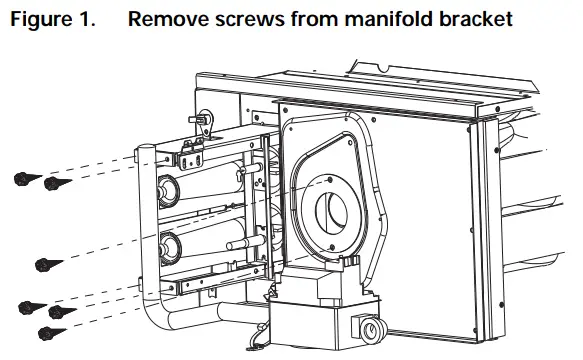
- Remove four screws from manifold bracket. See Figure 1, p. 6.

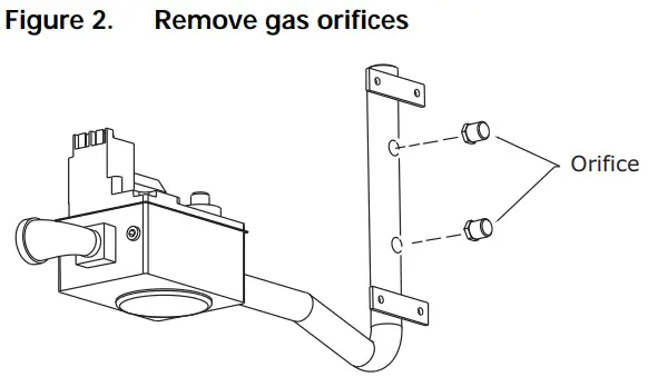
- Remove natural gas orifices from manifold. See Figure 2, p. 6.


- Install LP orifices, specified in Table 1, p. 5 (for FIALPKT002*), by engaging threads of manifold and tightening orifice three and one half turns.
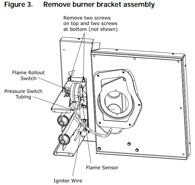
- Disconnect the wiring leads attached to the flame rollout switch, flame sensor, and igniter wire. See Figure 3, p. 6.
- Remove the four screws securing the burner bracket assembly to the heat exchanger vestibule.
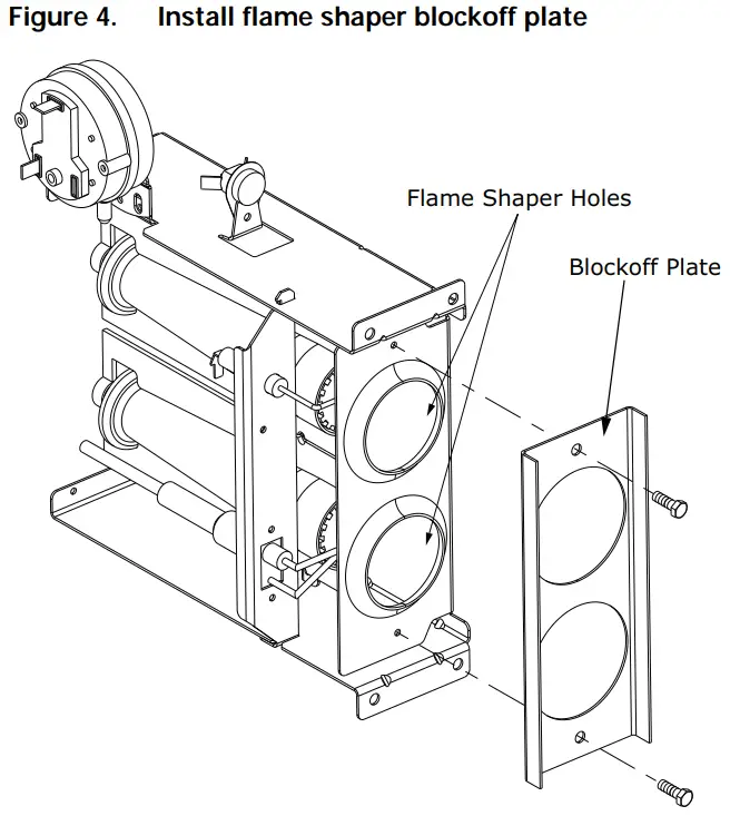
- Install the appropriate size flame shaper blockoff plate with two sheet metal screws provided. If there are no attachment holes in the burner bracket carefully secure utilizing the two self drilling screws. See Figure 4, p. 6.
- Reinstall burner bracket assembly with blockoff plate, reconnect all wiring and tubing connections, and reinstall manifold bracket with the LP orifices.
- If the unit model as listed in Table 1, p. 5 (for FIALPKT002*) requires a change to the air orifice plate or no orifice plate, perform Step 15 through Step 20; otherwise, proceed to Step 21.
- Disconnect the inducer motor wiring harness.
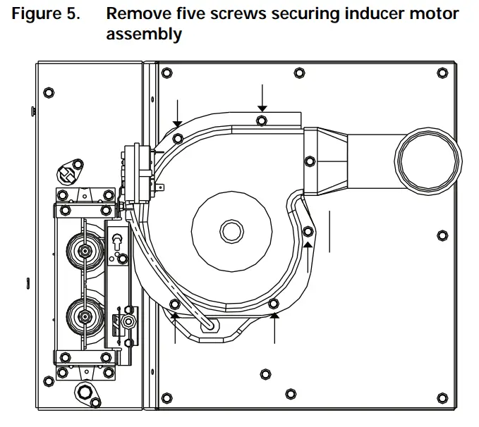
- Remove the five screws securing the inducer motor assembly (see Figure 5, p. 7).
- Remove the inducer motor assembly.
- Remove the two screws securing the air orifice plate (see Figure 1, p. 6).
- Remove or install the air orifice plate if required, as noted in Table 1, p. 5.
- Installation is the reverse of Step 15 through Step 18.

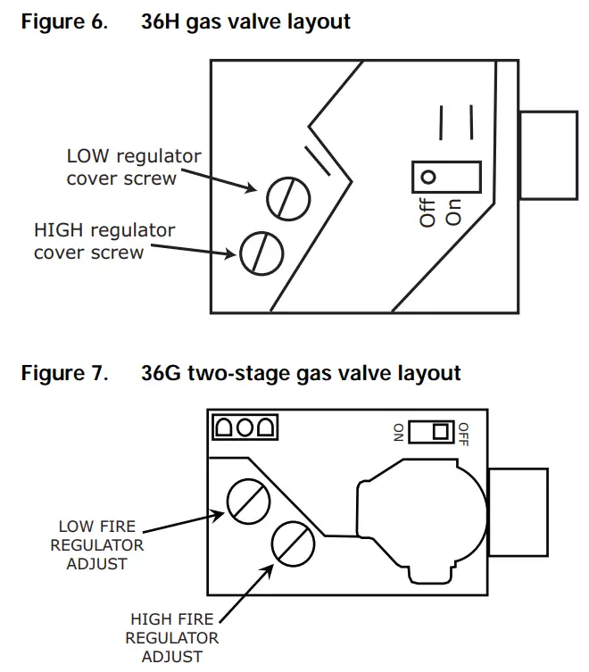
- Remove HIGH regulator brass cap.
- Remove regulator adjustment screw (beneath the cover screw).
- Remove the Natural Gas regulator spring from regulator sleeve (gold spring).
- Insert the LP regulator spring (provided in the included spring kit) into the regulator sleeve (white spring).
- Replace the regulator adjustment screw.
- Reverse the disassembly procedure and secure all components in their respective position.
- Reconnect gas valve wiring connector if disconnected previously.

- Attach the nameplate and label supplied with the conversion kit below the unit nameplate.
- Check all piping joints and electrical connections for tightness.
- Turn on the gas supply to unit.
- Measure the supply gas pressure. If the pressure exceeds 14 inches water column (34.8 mbar), reset the regulator at the gas supply.
- Restore unit power.
- Place the thermostat selector switch to the HEAT position and adjust the setpoint indicator to its highest setting.The burners should light.
- If required, adjust the unit high regulator manifold pressure to 10 inches water column (24.9 mbar) per the rating plate. Adjust the unit low regulator manifold pressure to 4.9 inches water column (12.2 mbar).
Note: A spring change is not required on the low regulator for LP. Install the access panel.
General Information
Follow these instructions to convert gas package unit models from natural gas to LP gas.
Important: Follow instructions closely. This is a critical procedure.
Inspection
- Unpack all components of the LP Conversion Kit.
- Check carefully for shipping damage. If any damage is found, report it immediately, and file a claim against the transportation company.
- This kit contains the correct parts required for LP conversion. Refer to Table 2, p. 8 to determine proper orifice selection.
Parts List
- Eight (8) Orifice Spuds, Drill #46 – 0.0810 in. Dia
- Eight (8) Orifice Spuds, Drill #47 – 0.0785 in. Dia
- One (1) LP Nameplate Label
- One (1) LP Conversion Literature
- One (1) LP Conversion Spring Kit
Table 2. Orifice size selection for FIALPKT003*
| Unit | Gas heat input rating (MBh) | LP Orifice Size |
| YSJ180A**(0,A)(L) | 250 | Drill #46 |
| YSJ180A**(0,A)(M) | 320 | Drill #47 |
| YSJ180A**(0,A)(H) | 400 | Drill #46 |
| YSJ210A**(0,A)(L) | 250 | Drill #46 |
| YSJ210A**(0,A)(M) | 320 | Drill #47 |
| YSJ210A**(0,A)(H) | 400 | Drill #46 |
| YSJ240A**(0,A)(L) | 250 | Drill #46 |
| YSJ240A**(0,A)(M) | 320 | Drill #47 |
| YSJ240A**(0,A)(H) | 400 | Drill #46 |
| YSJ300A**(0,A)(L) | 250 | Drill #46 |
| YSJ300A**(0,A)(M) | 320 | Drill #47 |
| YSJ300A**(0,A)(H) | 400 | Drill #46 |
Installation – FIALPKT003*
Conversion Procedure
Note: Conversion should be made prior to installation of equipment at the job site.
- Place the thermostat selector switch to the OFF position.
- Open the unit electrical disconnect switch.
- Shut off gas supply to the unit
- Remove gas valve access panel.
- Break pipe union.
- Remove pipe from street elbow.
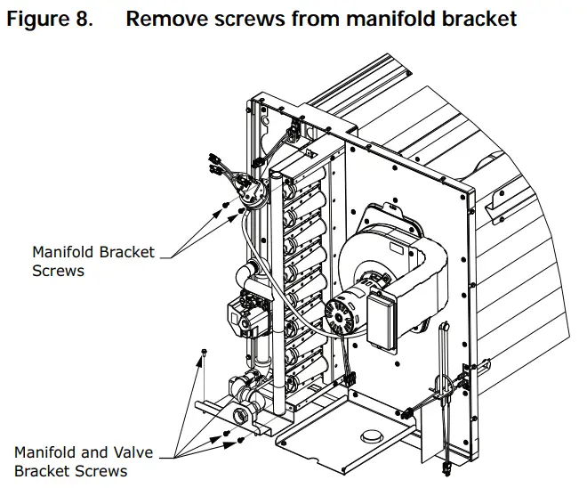
- Remove four screws from manifold bracket and two screws from valve support bracket. See Figure 8, p. 9.

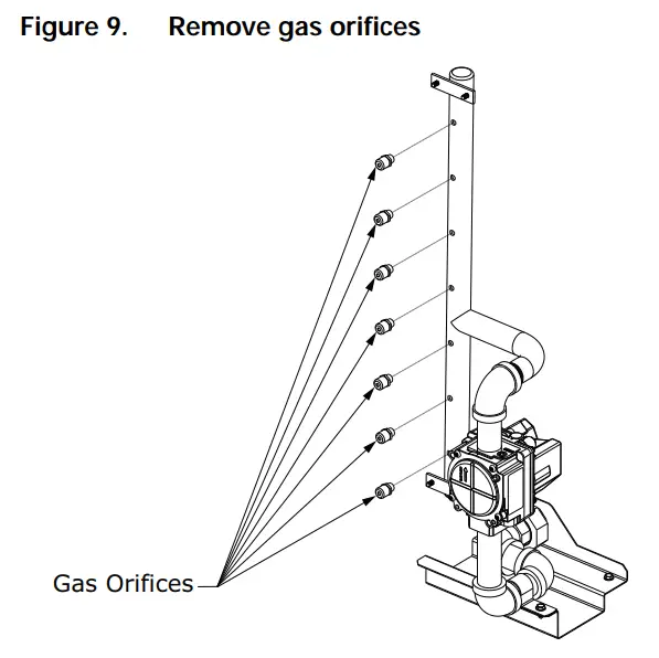
- Remove natural gas orifices from manifold. See Figure 9, p. 9.

- Install LP orifices specified in Table 2, p. 8. Engage threads of manifold and tighten orifice three- and onehalf turns.
- Install LP gas valve spring. Follow instructions provided with the conversion spring kit.
- With the LP orifices in place, reverse the disassembly procedure and secure all components in their respective position.
- Attach the nameplate and label supplied with the conversion kit below the unit nameplate.
- Check all piping joints and electrical connections for tightness.
- Turn on the gas supply to unit.
- Measure the gas pressure. If the pressure exceeds 14 inches water column (34.8 mbar), reset the regulator at the gas supply.
- Restore unit power.
- Place the thermostat selector switch to the HEAT position and adjust the setpoint indicator to its highest setting. The burners should light.
- Adjust the unit manifold pressure to 10 inches water column (24.9 mbar) per the rating plate.
- Install the access panel.
Trane and American Standard create comfortable, energy efficient indoor environments for commercial and residential applications. For more information, please visit trane.com or americanstandardair.com.
Trane and American Standard have a policy of continuous product and product data improvement and reserve the right to change design and specifications without notice. We are committed to using environmentally conscious print practices.
ACC-SVN229A-EN 29 Aug 2022
(NEW)


