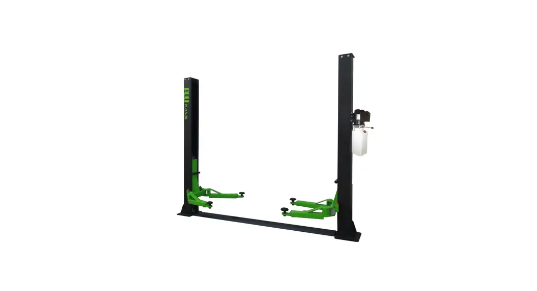
![]() FL-227EP Floor Plate Two Posts Lift
FL-227EP Floor Plate Two Posts Lift
Instruction Manual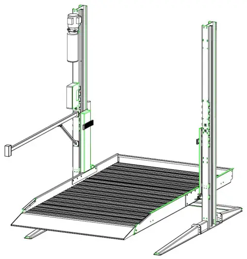
Please read this entire manual carefully and completely before installation or operation of the lift.
IMPORTANT SAFETY INSTRUCTIONS
1.1 Important notices
FRLEND will offer one-year’s quality warranty for the whole machine, during which any quality problem will be properly solved to the user’s satisfaction. However, we will not take any responsibility for whatever bad consequence resulted from improper installation and operation, overload running or unqualified ground condition.
This 2-posts lift is specially designed for lifting motor vehicles that weighs within its outmost lifting capacity. Users are not allowed to use it for any other purposes. Otherwise, we, as well as our sales agency, will not bear any responsibility for accidents or damages of the lift. Make sure to pay careful attention to the label of the lifting capacity attached on the lift and never try to lift cars with its weight beyond.
Read this manual carefully before operating the machine so as to avoid economic loss or personnel casualty incurred by wrong operation. Without professional advice, users are not permitted to make any modification to the control unit or whatever mechanical unit.
1.2 Qualified personnel
1.2.1 Only these qualified staff, who have been properly trained, can operate the lift.
1.2.2 Electrical connection must be done by a competent electrician.
1.2.3 People who are not concerned are not allowed in the lifting area.
1.3 Danger notices
1.3.1 Do not install the lift on any asphalt surface.
1.3.2 Read and understand all safety warnings before operating the lift.
1.3.3 The lift, if is not specially designed upon customer’s request, is not fit for outdoor use.
1.3.4 Keep hands and feet away from any moving parts. Keep feet clear of the lift when lowering.
1.3.5 Only these qualified people, who have been properly trained, can operate the lift.
1.3.6 Do not wear unfit clothes such as large clothes with flounces, tires, etc, which could be caught by moving parts of the lift.
1.3.7 To prevent evitable incidents, surrounding areas of the lift must be tidy and with nothing unconcerned.
1.3.8 The lift is simply designed to lift the entire body of vehicles, with its maximum weight within the lifting capacity.
1.3.9 Always insure the safety latches are engaged before any attempt to work near or under the vehicle.
1.3.10 Make sure to place the lifting pads to the positions as suggested by vehicle makers and when gradually lift the vehicle to the desired height, operators should be certain that the vehicle will not slant, roll-over or slide in lifting process.
1.3.11 Check at any time the parts the lift to ensure the agility of moving parts and the performance of synchronization. Ensure regular maintenance and if anything abnormal occurs, stop using the lift immediately and contact our dealers for help.
1.3.12 Lower the lift to its lowest position and do remember to cut off the power source when service finishes.
1.3.13 Do not modify any parts of the lift without manufacturer’s advice.
1.3.14 If the lift is going to left used for a long time, users are required to:
a. Disconnect the power source;
b. Empty the oil tank;
c. Lubricate the moving parts with hydraulic oil.
1.4 Training
Only these qualified people, who have been properly trained, can operate the lift. We are quite willing to provide professional training for the users when necessary.
Attention: For environment protection, please dispose the disused oil in a proper way.
1.5 Warning signs
All safety warning signs attached on the machine are for the purpose of drawing the user’s attention to safety operation. The labels must be kept clean and need to be replaced when they are worn-out or have dropped. Read the explanations of the labels carefully and try to memorize them.
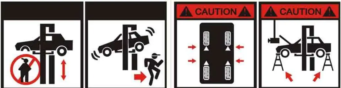 | |||
| Remain clear of lift when lowering or lifting vehicle. | Clear area if vehicle is in danger of falling. | Lift vehicle at the manufacturer s points | Always use safety stands when removing/ installing heavy components |
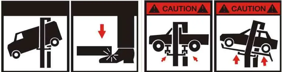 | |||
| Locate the vehicle with center gravity right between two adapters. | Keep feet away from adapter while lift lowering. | Use height extension when necessary to ensure good contact. | Auxiliary adapters may reduce load capacity. |
 | ||
| Do not override self – closing lift controls | Do not shake vehicle heavily while on lift | Read the manual before installation or operation of the lift |
![]() WARNING
WARNING
- Travelling on the load carrying devices is forbidden.
- After raising a short distance, checked to ensure that it is correctly and safely positioned.
- It is forbidden to climb onto the load or load carrying devices when they are raised.
| Lift is only allowed to be used by trained operator. | Only authorized personnel allowed in lift area |
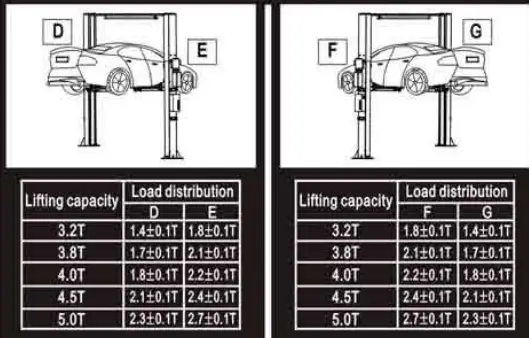
Arms must support the rated load weight as the following diagram.
OVERVIEW OF THE LIFT
2.1 General descriptions
This floor plate two posts lift is composed of posts, carriages, lifting arms, cylinders and motor unit, etc.
It is driven by an electro-hydraulic system. The gear pump delivers hydraulic oil to oil cylinders and pushes upwards its piston. The piston drives the chain to raise the carriage and the lifting arms. During lifting process, the safety latch will automatically and firmly bite with the safety teeth block in the posts. Therefore, no slipping will happen in case the hydraulic system breaks down.
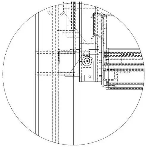
Safety structure
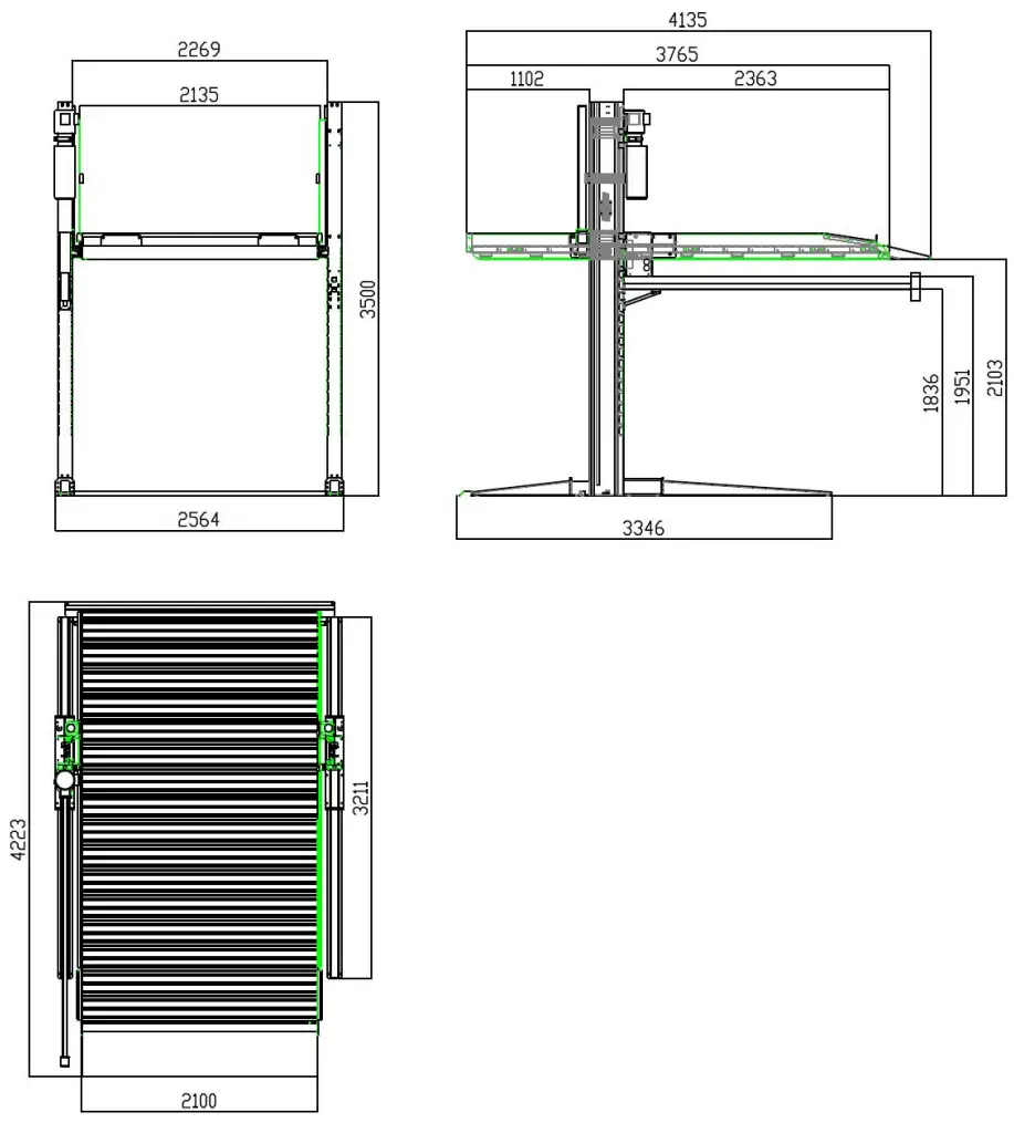
2.2 Technical data
| Model | Lifting capacity | Full rise time | Full rise | Height | Width | Inside columns |
| FL-227EP | 6000LB | 45 Sec | 2100mm | 3500mm | 2564mm | 2269mm |
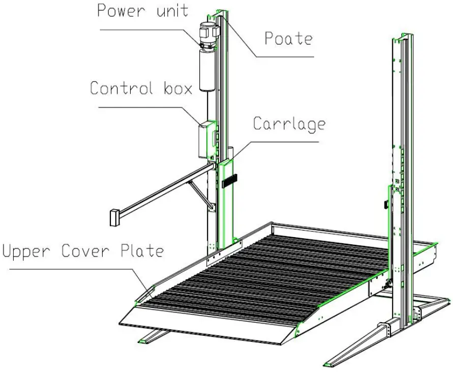
2.3 Construction of the lift
INSTALLATION INSTRUCTIONS
3.1 Preparations before installation
3.1.1 Tools and equipments needed![]() Appropriate lifting equipment
Appropriate lifting equipment![]() Anti-abrasion hydraulic oil.
Anti-abrasion hydraulic oil.![]() Rotary Hammer Drill with 3/4’’ drill bit.
Rotary Hammer Drill with 3/4’’ drill bit.![]() Chalk and tape measure, magnetic plump, 8 metersФ15 level pipe.
Chalk and tape measure, magnetic plump, 8 metersФ15 level pipe.![]() Sockets and open wrenches, a set of inside hex wrenches, cross and straight screw drivers.
Sockets and open wrenches, a set of inside hex wrenches, cross and straight screw drivers.![]() Hammer, 4pounds, sharp nose pliers, Ф17,Ф19,Ф22 socket spanners.
Hammer, 4pounds, sharp nose pliers, Ф17,Ф19,Ф22 socket spanners.
3.1.2 List for parts checking —Annex 1(Packing list)
Unfold the package and check if any parts missed as per Annex 1. Do not hesitate to contact us in case any parts missed, but if you do not contact us and insist installing upon the lack of some parts, FRLEND as well as our dealers will not bear any responsibility for this and will charge for any parts subsequently demanded by the buyer.
3.1.3 Ground conditions
The lift should be fixed on a smooth and solid concrete ground with its strength more than 3000psi, tolerance of flatness less than 5mm and minimum thickness of 200mm. In addition, newly built concrete ground must undergo more than 28days’ cure and reinforcement.
3.2 Precautions for installation
3.2.1 Make sure the two posts stand paralleled and are vertical to the ground. No slanting.
3.2.2 Joints of oil hose and steel cable must be firmly connected in order to avoid the looseness of steel cable and leakage of oil hose.
3.2.3 All bolts should be firmly screwed up.
3.2.4 Do not place any vehicle on the lift in the case of trial running.
3.3 Installation
Step 1: Remove the packaging, take out the carton for accessories and cover plate.
Step 2: Firstly, put something supporting between the two posts or suspend one of the posts by a crane and then remove the bolts on the package.
Attention: Please pay special attention not to let the post fall down for it may cause casualty or bring damages to the accessories fixed in the post.
Step3: When the first post has been taken away, place something supporter under the second post and then remove the bolts on the package.
Step 4: Erect the posts, power side post first and then the other post.
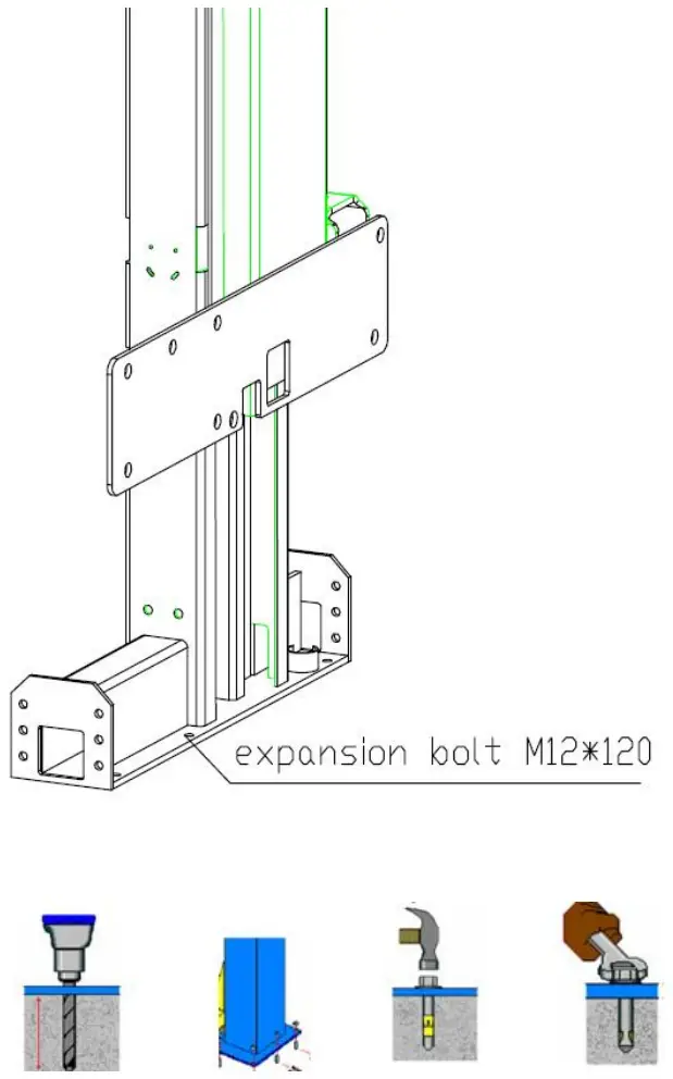
- Drill anchor holes for expansion bolts on the ground with an electrical drill. Make sure to drill vertically.
- After holes have been drilled, remove thoroughly the debris and dust in them and ascertain that the posts stay upon the circle previously drawn by chalk.

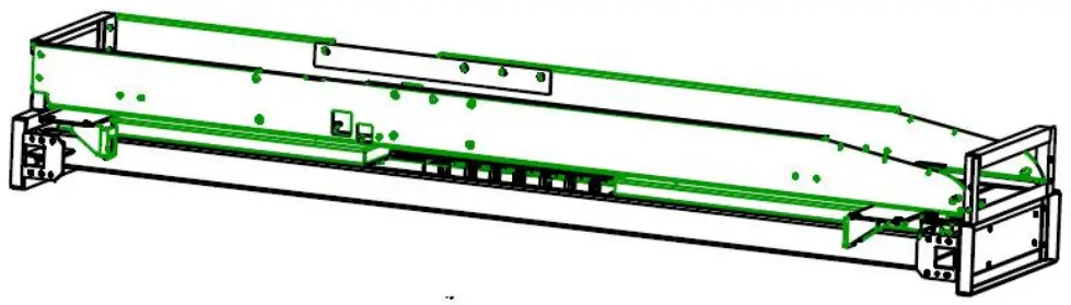
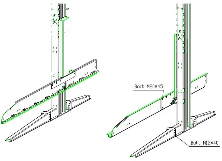
Step5: Leg side beam connection
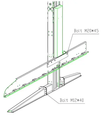
Step 6: Leg side beam connection
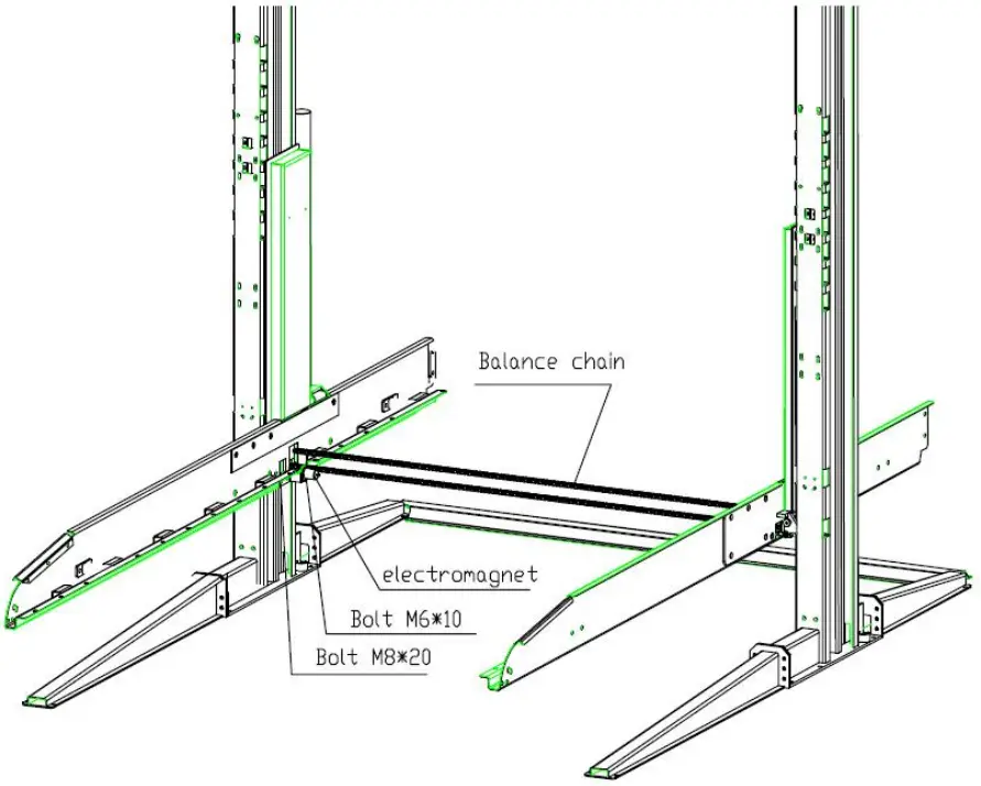
Step7: Balance chain, install electromagnet
Step8: Install the upper cover plate and connect the connecting rod.
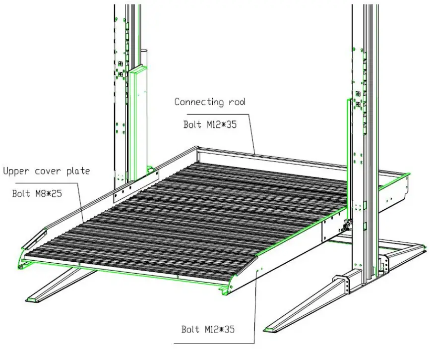
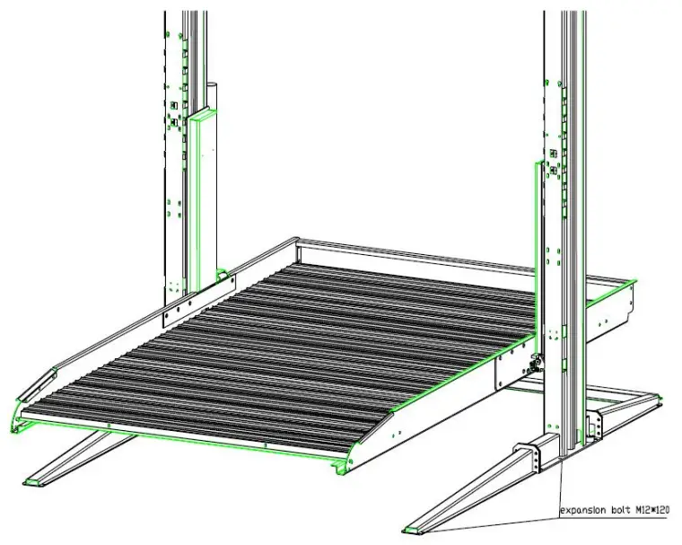
Step9: Beat expansion bolt
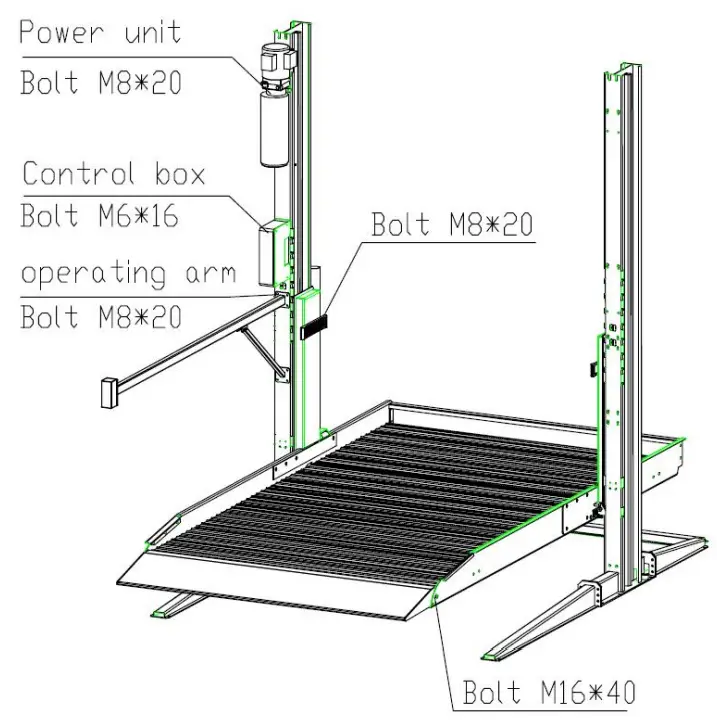
Step10: Install pump station and electrical box
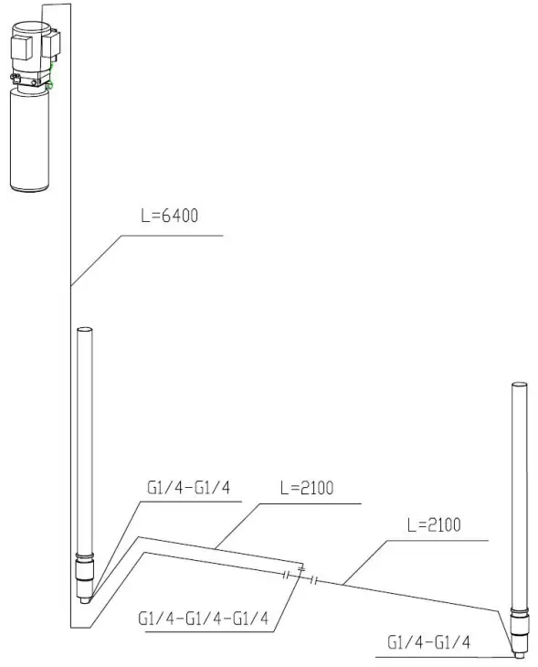
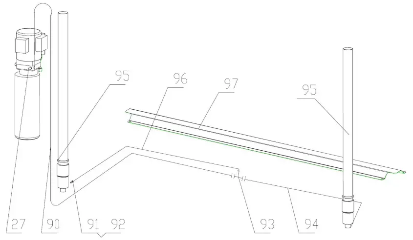
Step10: Connect oil hoses.
Connect the oil hose as per the following diagram.
3.4 Items to be checked after installation.
| S/N | Check items | YES | NO |
| 1 | Are the posts vertical to the floor? | ||
| 2 | Are the two posts paralleled? | ||
| 3 | Is the oil hose well connected? | ||
| 4 | Are electrical connections right? | ||
| 5 | Are the rest joints firmly screwed? | ||
| 6 | Are all items need lubricating added with grease? |
OPERATION INSTRUCTIONS
4.1 Precautions
4.1.1 Check all the joints of oil hose. Only when there is no leakage, the lift can start work.
4.1.2 The lift, if its safety device malfunctions, shall not be used.
4.1.3 The machine shall not lift or lower an automobile if its center of gravity is not positioned midway of the swing arms. Otherwise, the FRLEND as well as our dealers will not bear any responsibility for any consequence resulted thereby.
4.1.4 Operators and other personnel concerned should stand in a safety area during lifting and lowering process.
4.1.5 When lifting arms rise to the desired height, switch off the power at once to prevent any mal-operation done by unconcerned people.
4.1.6. Make sure the safety lock of the lift is engaged before start working under the vehicle and no people under the vehicle during lifting and lowering process.
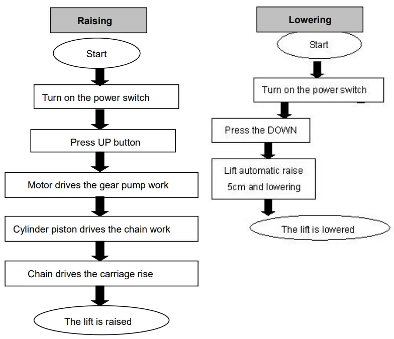
4.2 Flow chart for operation
4.3 Operation instructions
Raise the lift
- Make sure that you have read and understood the operation manual before operation.
- Park the vehicle between two posts.
- Connect the power supply as per requirements on the nameplate attached, and switch on.
- Press the ”UP” button on the control box until pads of lifting arms touched the prop-position of vehicle.
- Keep on raising the vehicle to let it have a bit clearance from the ground and check again its stability.
- Raise the vehicle to the desired height, check it is safe or not, press the “Safety Lock” button on the control panel to have the safety lock engaged, turn off the power and then perform maintenance or repair work underneath.
Lower the lift
- Switch on.
- Press the “DOWN” button on the control box. Meanwhile the lifting arms automatically go upwards about 5CM which releases the safety lock. The lift lowers.
- Drive the vehicle away.
TROUBLE SHOOTING
TTENTION: If the trouble could not be fixed by yourself, please do not hesitate to contact us for help .We will offer our service at the earliest time we can. By the way, troubles could be judged and solved much faster if more details or pictures could be provided.
| TROUBLES | CAUSE | SOLUTION |
| Abnormal noise | Abrasion exists on insider surface of the posts. | Grease the inside of the post. |
| Trash in the post. | Clear the trash | |
| Motor does not run and will not rise | The wire connection is loose. | Check and make a good connection. |
| The motor is blown. | Replace it. | |
| The limit switch is damaged or the wire connection is loose. | Connect it or adjust or replace the limit switch. | |
| Motor runs but will not raise | The motor run reversely. | Check the wire connection. |
| Overflow valve is loose or jammed. | Clean or adjust it. | |
| The gear pump is damaged. | Replace it. | |
| Oil level is too low. | Add oil. | |
| The oil hose became loose or dropped off. | Tighten it. | |
| The cushion valve became loose or jammed. | Clean or adjusts it. | |
| Carriages go down slowly after being raised | The oil hose leaks. | Check or replace it. |
| The oil cylinder is not tightened. | Replace the seal. | |
| The single valve leaks. | Clean or replace it. | |
| Solenoid valve fails to work well. | Clean or replace it. | |
| Steel cable is loose or not with same tightness | Check and adjust the tightness. | |
| Raising too slow | The oil filter is jammed. | Clean or replace it. |
| Oil level is too low. | Add oil. | |
| The overflow valve is not adjusted to the right position. | Adjust it. | |
| The hydraulic oil is too hot ( above 45°). | Change the oil. | |
| The seal of the cylinder is abraded. | Replace the seal. | |
| Inside surface of the posts is not well greased. | Add grease. | |
| Lowering too slow | The throttle valve jammed. | Clean or replace. |
| The hydraulic oil is dirty. | Change the oil. | |
| The anti-surge valve jammed. | Clean it. | |
| The oil hose jammed. | Replace it. | |
| The steel cable is abraded | No grease when installation or out of lifetime | Replace it. |
MAINTENANCE
Easy and low cost routine maintenance can ensure the lift work normally and safely. Following are requirements for routine maintenance. Frequency of routine maintenance is determined by working condition and frequency.
6.1. Daily checking items before operation
The user must perform daily check. Daily check of safety lock system in very important – the discovery of device failure before action could save time and prevent great loss, injury or casualty.
- Before operation, judge whether the safety locks are engaged by sound.
- Check whether oil hose well connected and whether it leaks or not.
- Check the connections of chain and steel cable and check the power unit.
- Check whether expansion bolts are firmly screwed.
- Check if arm lock works well or not.
1.2. Weekly checking items
- Check the flexibility of moving parts.
- Check the working conditions of safety parts.
- Check the amount of oil left in the oil tank. Oil is enough if the carriage can be raised to highest position. Otherwise, oil is insufficient.
- Check whether expansion bolt s firmly screwed.
6.3. Monthly checking items
- Check whether expansion bolts are firmly screwed.
- Check the tightness of the hydraulic system and screw firm the joints if it leaks.
- Check the lubrication and abrasion circumstance of axial pins, carriages, lifting arms and other related parts and replace in time with new ones if they failed to work well.
- Check the lubrication and abrasion circumstance of steel cable.
6.4. Yearly checking items
- Empty the oil tank and check the quality of hydraulic oil.
- Wash and clean the oil filter.
If users strictly follow the above maintenance requirements, the lift will keep in a good working condition and meanwhile accidents could be avoided to a large extent.
ANNEX
Annex1, Overall diagram
2700KG
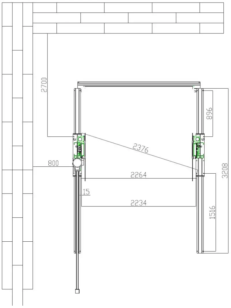
Annex2, Floor plan
2700KG
Annex 3, Hydraulic working system
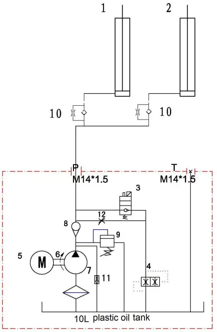
- Drive oil cylinder
- Assistant oil cylinder
- Manual unloading valve
- Throttle valve
- Motor
- Coupling
- Gear pump
- Single –way valve
- Over-flow valve
- Anti-surge valve
- Cushion valve
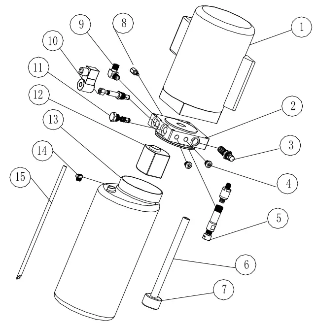
| S/N | Name | Qty |
| 1 | Motor | 1 |
| 2 | Hydraulic block | 1 |
| 3 | Overflow valve | 1 |
| 4 | Removable plug | 2 |
| 5 | Cushion valve | 1 |
| 6 | Oil absorbing pipe | 1 |
| 7 | Oil filter | 1 |
| 8 | Throttle valve | 1 |
| 9 | Oil pipe tie-in | 1 |
| 10 | E-magnetic unloading valve | 1 |
| 11 | One-way valve | 1 |
| 12 | Gear pump | 1 |
| 13 | Plastic oil tank | 1 |
| 14 | Oil tank cover | 1 |
| 15 | Oil back pipe | 1 |
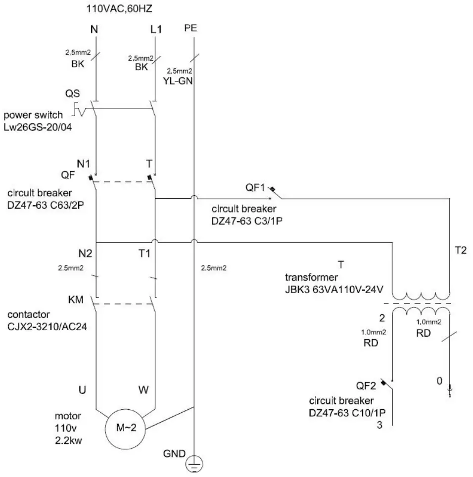
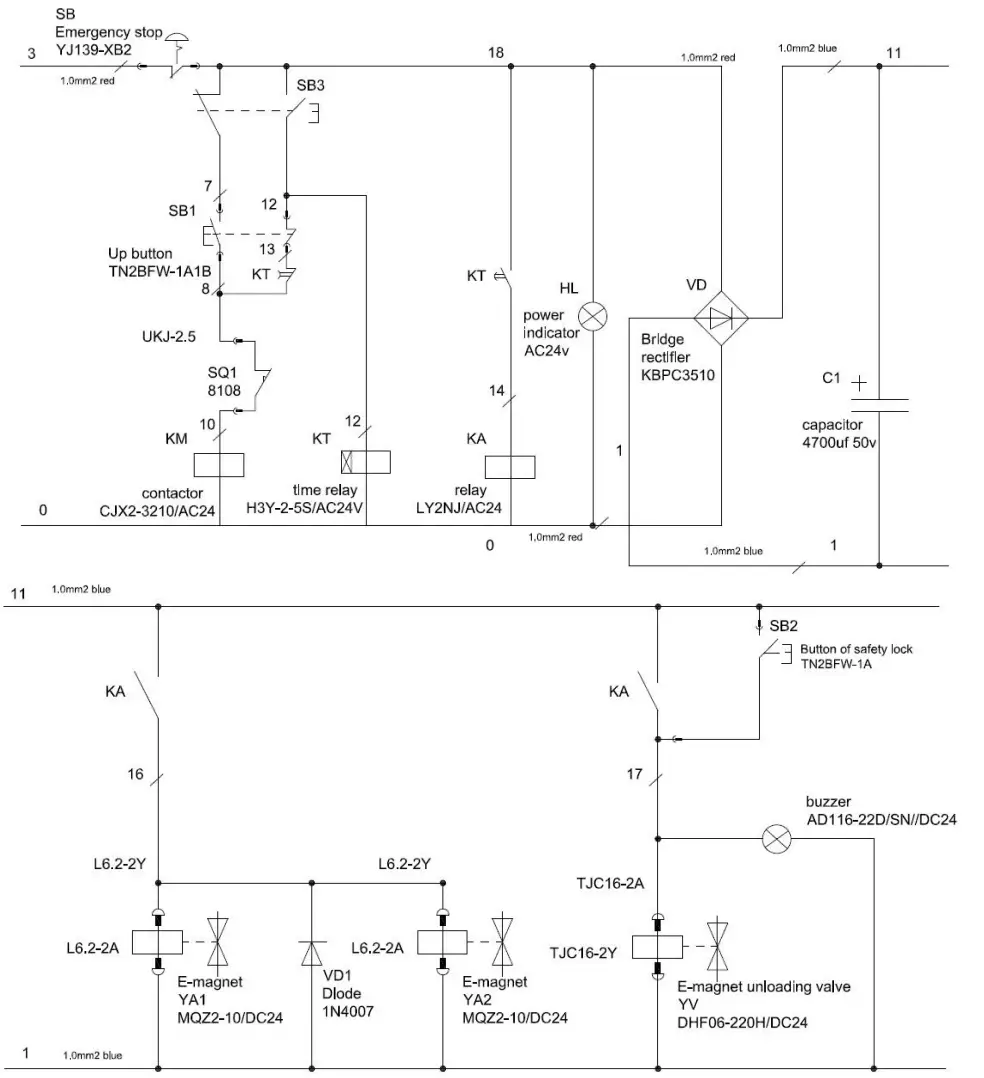
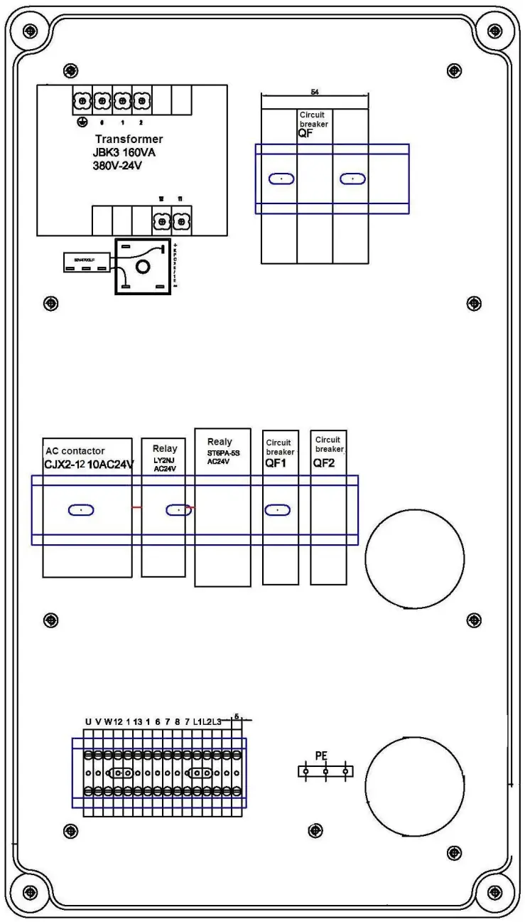
Annex4, Wiring diagram
Single phase
Annex5, Separated drawings for the lift
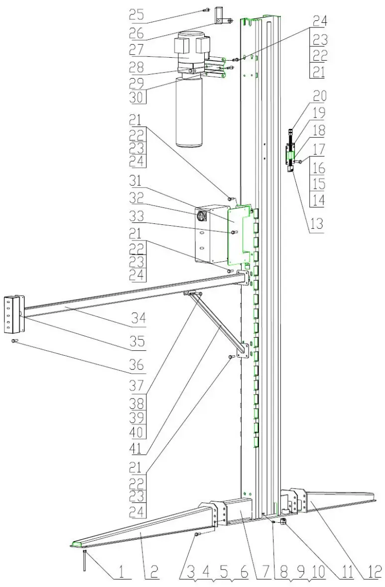
| S/N | Material # | Name | Drawing#/Spec. | Qty | Property | Note |
| 1 | Expansion bolt M12*120 | 24 | Standard | |||
| 2 | Front supporting leg weldment | FL-227EP-A1-B2 | 2 | Assembly | ||
| 3 | Outer hexagon bolt M12*35 | 24 | Standard | |||
| 4 | Spring washer 12 | 24 | Standard | |||
| 5 | Flat washer 12 | 24 | Standard | |||
| 6 | Nut M12 | 24 | Standard | |||
| 7 | Column weldment | 2 | Assembly | |||
| 8 | Hexagon socket screw M10*30 | GB/T70.1-2000 | 4 | Standard | ||
| 9 | Spring washer 10 | 4 | Standard | |||
| 10 | Flat washer 10 | 4 | Standard | |||
| 11 | Chain block | FL-227EP-A1-B5 | 2 | Assembly | ||
| 12 | Back supporting leg weldment | FL-227EP-A1-B3 | 2 | Assembly | ||
| 13 | Chain adjusting screw rod | FL-227EP-A1-B6 | 2 | Assembly | ||
| 14 | Outer hexagon bolt M10*35 | 8 | Standard | |||
| 15 | Spring washer 10 | 8 | Standard | |||
| 16 | flat washer 10 | 8 | Standard | |||
| 17 | Nut M10 | 8 | Standard | |||
| 18 | Fixing chain bracket | FL-227EP-A1-B4 | 2 | Assembly | ||
| 19 | Adjusting screw rod guide plate | FL-227EP-A1-B7 | 2 | Assembly | ||
| 20 | Nut M16(8.8) | 4 | Standard | |||
| 21 | Outer hexagon bolt M8*20 | 66 | Standard | |||
| 22 | Spring washer 8 | 66 | Standard | |||
| 23 | flat washer 8 | 66 | Standard | |||
| 24 | Nut M8 | 62 | Standard | |||
| 25 | Cross recess pan head M5*12 | 2 | Standard | |||
| 26 | Limit switch 8108 | 1 | Standard | |||
| 27 | Power unit | 1 | ||||
| 28 | Power unit mounting plate | 1 | Assembly | |||
| 29 | Outer hexagon bolt M10*20 | 2 | Standard | |||
| 30 | Spring washer 10 | 2 | Standard | |||
| 31 | Control box mounting plate | FL-227EP-A1-B9 | 2 | Assembly | ||
| 32 | Control box | 1 | ||||
| 33 | Cross recess pan head M6*15 | 12 | Standard | |||
| 34 | Support rods | FL-227EP-A1-B10 | 1 | Assembly | ||
| 35 | Operation box | 1 | ||||
| 36 | cross recess pan head M4*10 | 4 | Standard | |||
| 37 | Outer hexagon bolt M8*50 | 1 | Standard | |||
| 38 | Spring washer 8 | 1 | Standard | |||
| 39 | flat washer 8 | 1 | Standard | |||
| 40 | Nut M8 | 1 | Standard | |||
| 41 | Diagonal brace | FL-227EP-A1-B11 | Assembly |
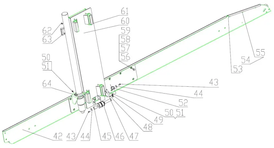
| S/N | Material # | Name | Drawing#/Spec. | Qty | Property | Note |
| 42 | Left beam weldment | FL-227EP-A2-B2 | 1 | Assembly | ||
| 43 | Cross recessed screw M6*10 | 4 | Standard | |||
| 44 | Big flat washer Ø30*Ø6.5*2 | 2 | Standard | |||
| 45 | Bearing 2530 | SF-1 | 4 | Standard | ||
| 46 | Balancer chain wheel | FL-227EP-A2-B3 | 4 | Assembly | ||
| 47 | Chain wheel | FL-227EP-A2-B4 | 2 | Assembly | ||
| 48 | Unlock black | FL-227EP-A2-B7 | 2 | Assembly | ||
| 49 | Fisheye bearing M8 | 2 | Standard | |||
| 50 | Outer hexagon bolt M8*35 | 4 | Standard | |||
| 51 | Lock nut M8 | 4 | Standard | |||
| 52 | Left torsional spring | FL-227EP-A2-B11 | 4 | Assembly | ||
| 53 | Left block wheel plate | FL-227EP-A2-B8 | 1 | Assembly | ||
| 54 | Cross recess pan head M6*15 | 6 | Standard | |||
| 55 | Lock nut M6 | 6 | Standard | |||
| 56 | Outer hexagon bolt M20*45 | 14 | Standard | |||
| 57 | Spring washer 20 | 14 | Standard | |||
| 58 | Flat washer 20 | 14 | Standard | |||
| 59 | Nut M20 | 14 | Standard | |||
| 60 | Left carriage weldment | FL-227EP-A2-B1 | 1 | Assembly | ||
| 61 | Slider 120*55*32 | FL-227EP-A2-B6 | 8 | Assembly | ||
| 62 | Cross recessed countersunk | 4 | Standard | M8*20 | ||
| 63 | 5T protection rubber pad | 2 | Assembly | |||
| 64 | Clamp | FL-227EP-A13 | 2 | Assembly |
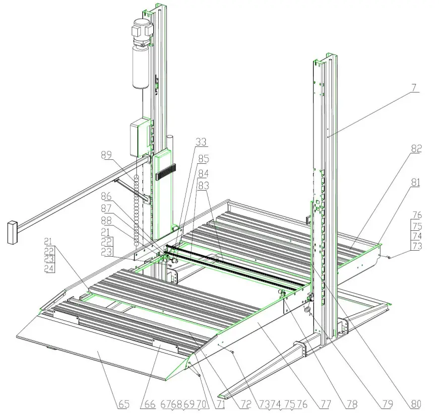
| S/N | Material # | Name | Drawing#/Spec. | Qty | Property | Note |
| 65 | Ramp weldment | FL-227EP-A6 | 1 | Assembly | ||
| 66 | Block wheel plate | FL-227EP-A14 | 2 | Assembly | ||
| 67 | Outer hexagon bolt M16*40 | 4 | Standard | |||
| 68 | Spring washer 16 | 4 | Standard | |||
| 69 | Flat washer 16 | 4 | Standard | |||
| 70 | Nut M16 | 4 | Standard | |||
| 71 | Right block wheel plate | FL-227EP-A3-B3 | 1 | Assembly | ||
| 72 | Connecting rod | FL-227EP-A4 | 4 | Assembly | ||
| 73 | Outer hexagon bolt M12*35 | 20 | Standard | |||
| 74 | Spring washer 12 | 20 | Standard | |||
| 75 | Flat washer 12 | 20 | Standard | |||
| 76 | Nut M12 | 20 | Standard | |||
| 77 | Right beam weldment | FL-227EP-A3-B2 | 1 | Assembly | ||
| 78 | Electromagnet mounting plate | FL-227EP-A8 | 1 | Assembly | right | |
| 79 | Right torsional spring | FL-227EP-A2-B12 | 1 | Assembly |
| 80 | Right carriage weldment | FL-227EP-A3-B1 | 1 | Assembly | ||
| 81 | Back beam weldment | FL-227EP-A5 | 1 | Assembly | ||
| 82 | waved plate | FL-227EP-A9 | 16 | Assembly | ||
| 83 | Chain 2.7T | 301 节-15.9 | 2 | |||
| 84 | Chain support plate | FL-227EP-A12 | 1 | Assembly | ||
| 85 | Electromagnet | MQZ2-10N-15 | 2 | Assembly | ||
| 86 | Unlock tension spring | FL-227EP-A2-B10 | 2 | Assembly | ||
| 87 | Adjusting screw rod | FL-227EP-A7 | 2 | Assembly | ||
| 88 | Electromagnet mounting plate | FL-227EP-A8 | 1 | Assembly | left | |
| 89 | Spring wire 2*0.5 | 2*0.5 | 2M | Standard |
| S/N | Material # | Name | Drawing#/Spec. | Qty | Property | Note |
| 90 | Oil pipe L=6500 | Bend +streight | 1 | Assembly | ||
| 91 | Combined washer | 13.74*20.57*2.03 | 2 | Assembly | ||
| 92 | Oil pipe joint | G1/4 throttle-G1/4 inner | 2 | Assembly | ||
| 93 | T junction | 3-G1/4 | 1 | Assembly | ||
| 94 | Oil pipe L=2200 | 2 strsight | 1 | Assembly | ||
| 95 | Oil cylinderφ55*2140 | FL-227EP-A2-B5 | 2 | Assembly | ||
| 96 | Oil pipe L=2200 | Bend +streight | 1 | Assembly | ||
| 97 | Oil pipe cover plate | FL-227EP-A11 | 1 | Assembly | ||
Annex 6, Spare parts list
| S/N | Material # | Name | Spec. | Qty | Pic. | Note |
| 1 | Power switch | LW26GS-20/04 | 1 |  | ||
| 2 | Button | Y090-11BN | 1 |  | ||
| 3 | Power indicator | AD17-22G-AC24 | 1 |  | ||
| 4 | Transformer | JBK3-160VA380V-24V JBK3-160VA220V-24V | 1 |  | ||
| 5 | AC contactor | CJX2-1210/AC24 | 1 |  | ||
| 6 | Circuit breaker | DZ47-63 C16/3P DZ47-63 C32/2P | 1 |  | ||
| 7 | Circuit breaker | DZ47-63 C3/1P | 1 |  | ||
| 9 | Limit switch | ME8108 | 1 |  | ||
| 11 | Emergency stop | Y090-11ZS/red | 1 |  | ||
| 12 | Bridge rectifier | KBPC5A-35A | 1 |  | ||
| 13 | Capacitor | 4700UF/50A | 1 |  | ||
| 14 | Relay | LY2NJ/AC24 | 1 |  | ||
| 15 | Relay holder | PTF-08A | 1 |  | ||
| 16 | time relay | ST6PA-5S/AC24V | 1 |  | ||
| 17 | Time relay holder | PYF-08AE | 1 |  | ||
| 18 | Control box | 380*230*135 | 1 |  |
![]() www.zg-friend.com
www.zg-friend.com
Lifting Capacity 6000LB
Distributed by


