![]() Electric Bike Display
Electric Bike Display
KD21C
User Manual
Product name and model
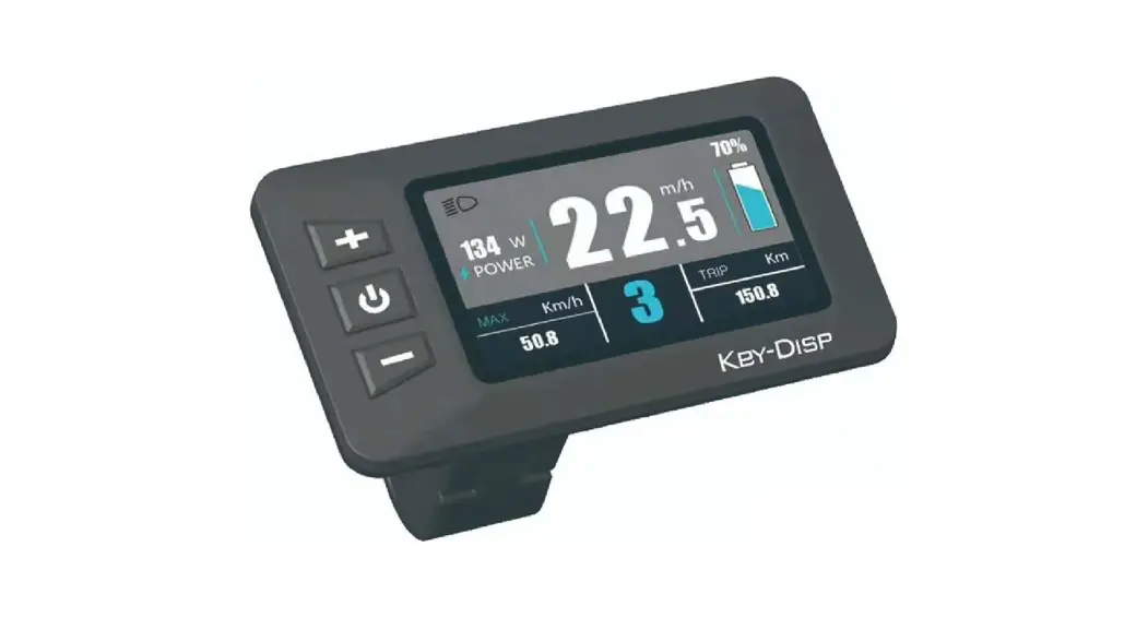
Intelligent LCD display of eBike; model: KD21C.
Specifications
- 24V/36V/48V Power Supply
- Rated working current: 10mA
- The maximum working current: 30mA
- Off leakage current: <1uA
- The supply controller working current: 50mA
- Working temperature:-20 ℃~ 60℃
- Storage temperature: -30 ℃~ 70℃
Appearance and Size
Display appearance and dimension figure (unit: mm)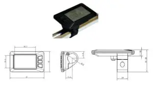
Color categories
Top shell of the display is two color options, black and white, and the bottom shell of the display is only one black.
Function Summary
KD21C can provide a lot of functions to fit the users’ needs. The indicating contents are as follows
- Smart Battery indicator
- Motor-output indication
- Assistance-level indication
- Speed indication (incl. running speed, max speed, and average speed)
- Trip distance and total distance
- The push-assistance function
- Trip time display of a single
- The Lighting On/Off
- Error Code indication
- Various Parameters Settings (e.g. wheel size, speed-limited, battery level bar, assistance level, controller limited current, max peed, password enable, etc.)
- Recover Default Settings
Functional Area Distribution
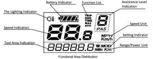
There are three buttons (M, +, – ) on the KD21C
display that represented by the following functions respectively: MODE, UP, DOWN.
General Operation
Switching the eBike System On/Off
To switch on the eBike system, hold the MODE button for 2s.
In the same way to hold the MODE button for 2s again, the eBike system will be switched off.
When switching off the eBike system the leakage current is less than 1 uA.
- When parking the eBike for more than 10 minutes, the eBike system switches off automatically.
Display Interface
After switching on the eBike system, the display shows Running Speed and Total Distance except battery indicator and assistance level. To change the indicated information, press the MODE button to show in turn as below: Running Speed (Km/h) → Trip Distance (Km) →Trip Time (Hour.) → Max Speed (Km/h) → Average Speed (Km/h) → Motor Power (W) → Running Speed (Km/h).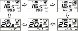
Switching Push-assistance mode On/Off
To access the push-assistance mode, hold the DOWN button always, the eBike will go on at a uniform speed of 6 Km/h, “P” is
shown on the screen at the same time. The push-assistance function switches off as soon as you release the DOWN button.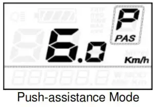
The push-assistance function may only be used when pushing the eBike. The danger of injury when the wheels of the eBike do not have ground contact while using the push-assistance function.
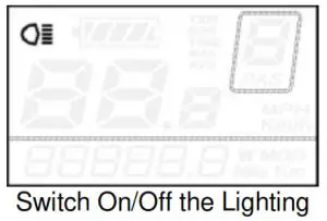
Switching the Lighting On/Off
To switch on the display backlight and headlight of the eBike, hold the UP button for 2s.
In the same way to hold the UP button for 2s again, the backlight and the headlight will be switched off.
Assistance Level Selection
Assistance levels indicate the output power of the motor. The default value is level “1”.
The default power ranges from level “0” to level “5”.The output power is zero on Level “0”. Level “1” is the minimum power. Level “5” is the maximum power. Gear to level “5” and then press the UP button, the interface shows “5” still and “5” flashing prompts top. Gear to level “0” and then press the DOWN button, the interface shows “0” still and “0” flashing prompts low.
To change the assistance level, press the UP/DOWN to increase or decrease until the desired assistance level is displayed.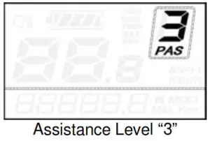
Battery Indicator
The five battery bars represent the capacity of the battery. When the battery is in low voltage, the battery frame will flash to notice that the battery needs to be recharged immediately.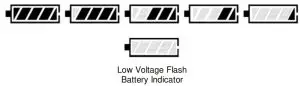
Error Code Indication
If there are errors about the electronic control system, the error code will appear automatically. Here is the message of the error code in Attached list 1. 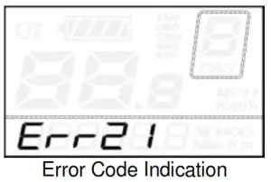
Offer the display to a Service Center when an error code appears.
General Settings
After the eBike system is switched on, to access the general settings menu, hold both the UP and DOWN button for 2s.
All the Settings are operated in the case of parking the bike.
Trip Distance Clearance
TC represents the trip distance clearance setting.
To the clear trip distance, press the UP/DOWN button to choose Y or N.
The default value is N.
To store a changed setting, press the MODE button and then access backlight contrast settings.
Various symbol definitions refer to Attached list 4.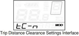
Backlight Contrast settings
bL represents backlight contrast settings. Level “1” is the low brightness. Level “2” is the middle brightness. Level “3” is high brightness.
The default value is “1”.
To modify the backlight brightness, press the UP/DOWN button to increase or decrease until the desired setting is displayed.
To store a changed setting, press the MODE button and then access unit Conversion Settings.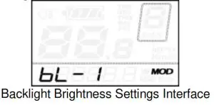
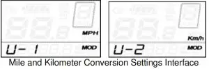
Unit km/mi Conversion
U represents unit settings, “1” is a mile, “2” is a kilometer. The default value is “2”.
To convert the unit, press the UP/DOWN button to increase or decrease until the desired setting is displayed.
To store a changed setting, press the MODE button, and then access trip distance clearance settings.
To store a changed setting, hold the MODE button for 2s and then exit general settings.
General Parameter Settings
To access the general parameter Settings interface, hold both the UP and the DOWN buttons for 2s, then hold both the DOWN and MODE buttons for 2s again.
Wheel Diameter Settings
Ld represents wheel diameter settings. Electable values are 16, 18, 20, 22, 24, 26, 700C and 28. The default value is 20 inch.
To change basic settings, press the UP/DOWN button to increase or decrease until the desired value is displayed.
To store a changed setting and access the speed-limit settings interface, press the MODE button.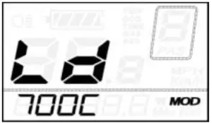
Wheel Diameter Settings Interface
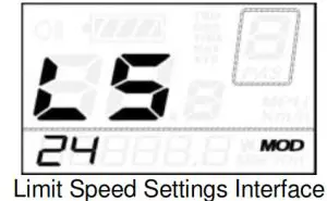
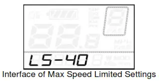
Speed-limit Settings
LS represents the limit speed settings. When the running speed is faster than the limit speed, the eBike system will switch off automatically. Limit speed ranges from 12Km/h to 40Km/h. The default value is 25Km/h.
To change basic settings, press the UP/DOWN button to increase or decrease until the desired value is displayed.
To store a changed setting and exit General Parameter Settings, hold the MODE button for 2s.
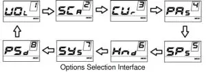
Personalized Parameter Settings
Personalized Parameter Settings can match a variety of requirements in use. There are 8 Settings items, such as Battery Power Bar Settings, Power assistant level Settings, Over-current Cut Settings, Power Assistant Sensor Settings, Speed Sensor Settings, Throttle Function Settings, System Settings, and Power-on Password Settings. Please refer to the Attached list 2. To access the Personalized Parameter Settings items option page, hold both the UP and DOWN button for 2s, then hold both the UP and DOWN button again.
To access the corresponding settings page, press the UP/DOWN button to increase or decrease until the desired item is displayed, and press the MODE button again.

Battery Power Bar Settings
VOL represents voltage settings. Each bar represents a voltage value. 5 bars voltage values must be entered one by one. For example, VOL 1 is the first bar voltage value, the default value is 31.5.
To set the battery power bar, press the UP/DOWN button to increase or decrease the number.
To store a changed setting and access the second bar, press the MODE button. By analogy, after 5 bars of voltage values are entered, hold the MODE button to confirm and return to the previous menu.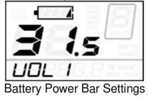
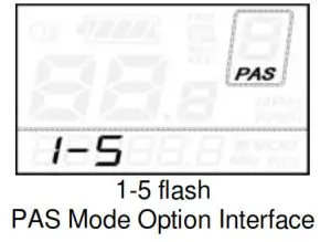
Assistance Level Settings
Assistance Level option
In assistance level settings, there are 8 modes to select: 0-3, 1-3, 0- 5, 1-5, 0-7, 1-7, 0-9, 1-9. The default value is 0-5.
To select the mode of assistance level, press the UP/DOWN button to increase or decrease until the desired setting is displayed. To store the changed setting and access the PAS ratio settings page, press the MODE button.
PAS Ratio Settings
To modify the value of the PAS ratio can match the different requirements. For example, the range is “45-55 percent” of “1” level, the bottom value can be modified, and the default value is 50 percent.
To store the modified setting, press the MODE button and turn to the next PAS ratio settings. After all PAS ratio inputted, hold the MODE button for 2s to confirm and then return to the previous menu. Please refer to Attached list 3.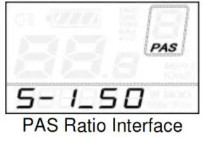
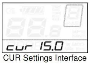
Controller Over-Current Cut Settings
CUR represents controller over-current cut settings. CUR value can be changed from 7.0A to 22.0A. The default value is 15A.
To change basic settings, press the UP/DOWN button to increase or decrease the value of the current.
To store a changed setting, hold the MODE button and then return to the previous menu.
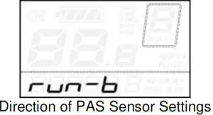
Power Assistant Sensor Settings
The Direction of Power Assistant Sensor Settings
PAS represents power assistant sensor settings. “run-F” means forward direction, while “run-b” means back direction. The default value is “run-F”.
To change The Direction of Power Assistant Sensor Settings, press the UP/DOWN button to select F or b. To store a changed setting, press the MODE button and then access the settings mode of PAS sensitivity.
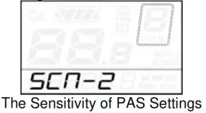
The Sensitivity of PAS Settings
SCN represents the sensitivity of PAS settings. The sensitivity value ranges from “2” to “9”. “2” is the strongest, “9” is the weakest. The default value is “2”. To change the sensitivity of PAS settings, press the UP/DOWN button o to select the sensitivity value. To store a changed setting, press the MODE button and then access magnet disk settings mode.
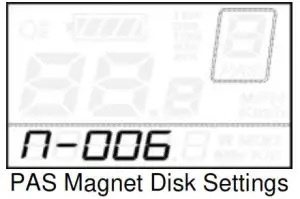
Magnet quantity Settings
N represents magnet numbers of PAS disk. The default value is 6. To change magnet numbers To store a changed setting, hold the MODE button and then return to the previous menu.
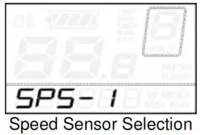
Speed Sensor option
SPS represents speed sensor settings. The default value is 1 To change speed sensor settings, press the UP/DOWN button to elect the quantity of magnet head (the range is from 1 to 9).
To store a changed setting, hold the MODE button and then return to the previous menu.
Throttle Definition
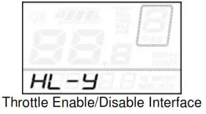
Throttle Push-assistance Enable/Disable
HL represents the throttle push-assistance function. HL-N represents throttle assistance push function is disabled. HL-y represents throttle assistance push function is enabled. The default value is N. To change the throttle push-assistance function, press the UP/DOWN button to select Y. To store a changed setting, press the MODE button. Otherwise, to select N and then access Throttle Level Enable Settings.
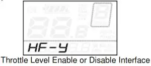
Throttle Level Enable/Disable
HF-y represents throttle level is enabled. HF-N represents throttle level is disabled. The default value is N. To change the throttle level function, press the UP/DOWN button to select Y or N.
To store a changed setting, press the MODE button and then access the Throttle Enable Settings page. To return to the previous menu, hold the MODE button for 2s.
 System Settings
 System Settings
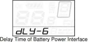
Delay time settings of battery power
DLY represents the delay time of battery power settings. The default value is 3s.
To change delay time settings, press the UP/DOWN button to select delay time 3s, 6s, 12s.
To store a changed setting, press the MODE button and then access the max speed limited.
Max speed limited
MAX SPD represents max speed limited settings. The default value is 40Km/h.
To change Max speed limited setting, press the UP/DOWN button to set the max speed from 25Km/h to 40 Km/h.
To store a modified setting, press the MODE button and then access Button PAS Settings.
This setting is the priority version. The speed is the maximum set by the manufacturer.
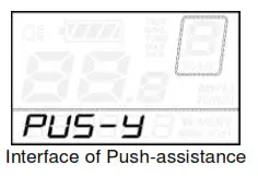
Button Push-assistance Enable/Disable
PUS represents button push-assistance settings. Y represents button push is enabled, N represents button push is disabled. The default value is Y.
To change button push-assistance settings, press the UP/DOWN button to choose Y or N.
To store a changed setting, press the MODE button and then access PAS speed settings.
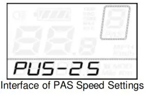
PAS Speed Settings
To change PAS speed settings, press the UP/DOWN button to adjust from 20% to 35%,
To store a modified setting, press the MODE button and then access slowly startup.
The default value is 25%.
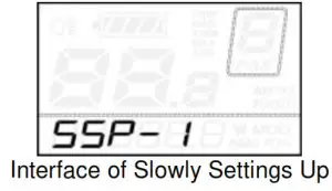
Slowly Startup Settings
SSP represents slowly start-up. The range is “1-4”, “4” is the slowest. The default value is “1”.
To change slowly startup settings, press the UP/DOWN button to select the desired value.
To store a changed setting, press the MODE button and then turn to the Delay time settings of the battery power page.
To return to the previous menu, hold the MODE button for 2s.
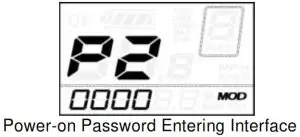
Power-on Password Settings
P2, 0000 on the screen means power-on password settings. The default value is 2222.
To access the power-on password settings, press the UP/DOWN button to modify the value and then press the MODE button to confirm digit one by one until the correct 4-digit password is completed, and then press the MODE button to access the power-on password enable settings interface, otherwise stay on the password input state.
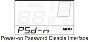
Power-on Password Enable/Disable
To change power-on password enable/disable settings, press the UP/DOWN button to select Y or N.
If it is Y, press the MODE button and then access the power-on password modify the interface, otherwise exit the power-on password settings interface. The default value is N. Y is power-on password enable N is power-on password disable
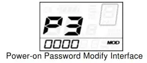
Power-on Password Modify
When the display shows P3, 0000, to set a new power-on password, press the UP/DOWN button to modify the value and then press the MODE button to confirm digits one by one until the new 4-digit password is completed.
To store the new power-on password, hold the MODE button for 2s and then exit settings.
When switching the eBike system on next time, the display will show P1,0000, please input the new password to power on.
Exit settings
In the settings state, pressing the MODE button is to confirm the input. Holding the MODE button is to store the settings, and then exit the current settings. Holding the DOWN button is to cancel the operating but not storing settings data, and then return to the previous menu.
If there is not no operations in one minute, the display will exit the settings state.
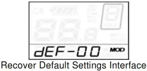
Recover default settings
dEF represents recover default settings. The default value is N. To access recover default settings, hold both the UP and MODE
button for 2s and press the UP/DOWN button to choose Y or N again. N means that do not recover default settings. Y means that recovers default settings.
When it is Y, hold the MODE button for 2s to recover default settings, the display shows DEF-00 at the same time, and then returns to the general display state.
Operation Cautions
Be careful of safe use. Don’t attempt to release the connector when the battery is on power.
- Try to avoid hitting.
- Don’t modify system parameters to avoid parameters disorder.
- Make the display repaired when the error code appears.
Quality assurance and warranty scope
Ⅰ Warranty
- The warranty will be valid only for products used in normal usage and conditions.
- The warranty is valid for 24 months after the shipment or delivery to the customer.
Ⅱ Other items
The following items do not belong to our warranty scope:
- The display is demolished.
- The damage to the display is caused by the wrong installation or operation.
- The shell of the display is broken when the display is out of the factory.
- The wire of the display is broken.
- Beyond the Warranty period.
- The fault or damage of the display is caused by the force majeure (e.g., fire, earthquake, etc.).
Connection layout
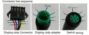
Line sequence table
| Line sequence | Color | Function |
| 1 | Red(VCC) | + |
| 2 | Blue(K) | Lock |
| 3 | Black(GND) | – |
| 4 | Green(RX) | RX |
| 5 | Yellow(TX) | TX |
Some wires use the water-proof connector, users can not see the inside color.
Attached list 1:Error code definition
| Error Code | Definition |
| 21 | Current Abnormality |
| 22 | Throttle Abnormality |
| 23 | Motor Abnormality |
| 24 | Motor Hall Signal Abnormality |
| 25 | Brake Abnormality |
| 30 | Communication Abnormality |
Attached list 2: Personality Parameter settings
| No. | Settings item | Screen display |
| 1 | Battery Power Bar Settings | 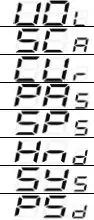 |
| 2 | Power assistant level Settings | |
| 3 | Over-current Cut Settings | |
| 4 | Power Assistant Sensor Settings | |
| 5 | Speed Sensor Settings | |
| 6 | Throttle Function Settings | |
| 7 | System Settings | |
| 8 | Power-on Password Settings |
Attached list 3:Power assist table
| Level/ Level Item | 1 | 2 | 3 | 4 | 5 | 6 | 7 | 8 | 9 |
| 0-3/ 1-3 | 50% | 74% | 92% | — | — | — | — | — | — |
| 0-5/ 1-5 | 50% | 61% | 73% | 85% | 96% | — | — | — | — |
| 0-7/ 1-7 | 40% | 50% | 60% | 70% | 80% | 90% | 96% | — | — |
| 0-9/ 1-9 | 25% | 34% | 43% | 52% | 61% | 70% | 79% | 88% | 96% |
Attached list 4:symbol definition
| No. | Symbol | Definition |
| 1 | 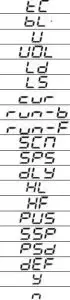 | Trip distance clearance |
| 2 | Backlight | |
| 3 | Unit | |
| 4 | Voltage | |
| 5 | Wheel diameter | |
| 6 | Speed limit | |
| 7 | Controller over-current cut | |
| 8 | Backward | |
| 9 | Forward | |
| 10 | Sensitivity of PAS | |
| 11 | Speed sensor | |
| 12 | Power delayed time | |
| 13 | Throttle power assist walk | |
| 14 | Throttle-changing | |
| 15 | Button push | |
| 16 | Slowly startup | |
| 17 | Password | |
| 18 | Recover default | |
| 19 | Yes | |
| 20 | No |


