CMACEWHEEL YL91F-V Electric Bike Display
Product Name and Model Number
Smart LCD display for electric bicycle; Model: YL91F-V.
Specification
- 36V/48V/52V power supply
- Display rated current 15mA
- Display maximum current 30mA
- Shutdown leakage current <1uA
- Supplied current to the controller 50mA
- Operating temperature -20~60℃
- Storage temperature -30 to 70°C3.
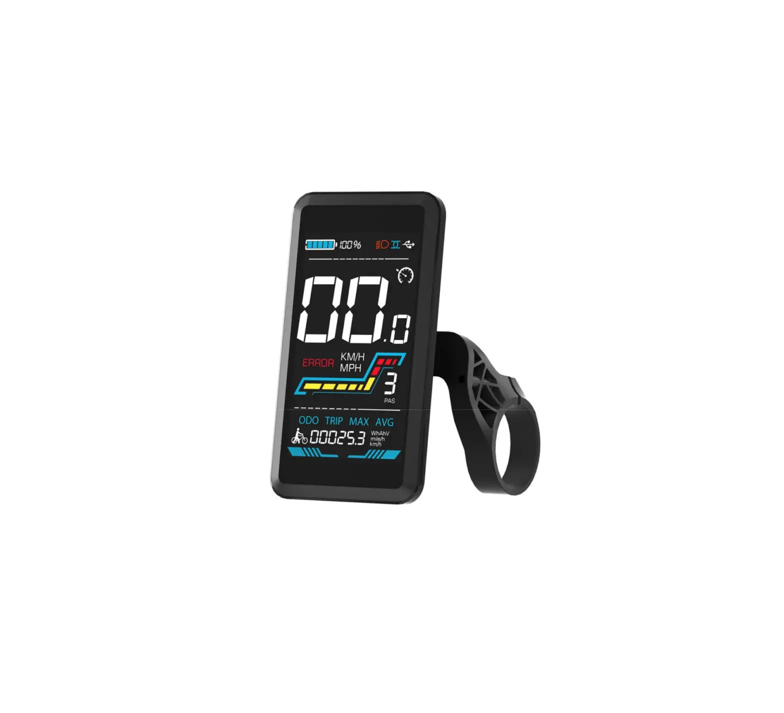
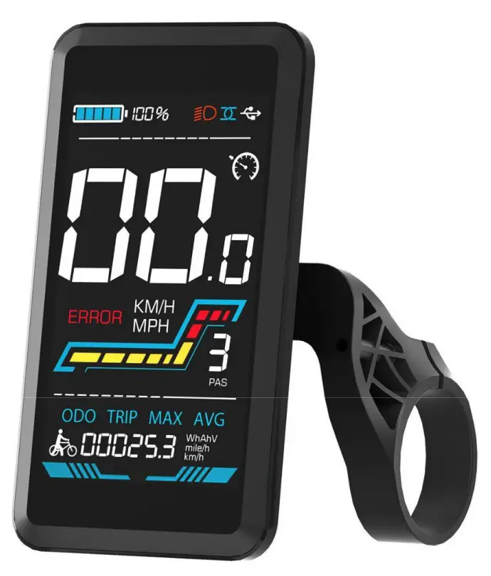
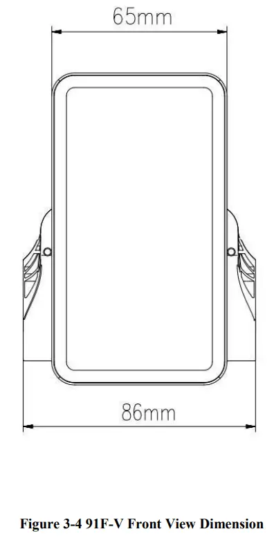
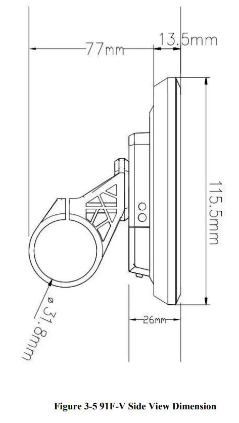
Appearance and Size
Figure 3-1 Physical picture of the YL91F-V display
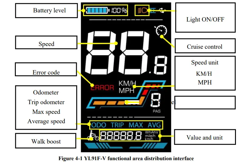
Function overview and Functional areas
Functional overview
The YL91F-V display offers a variety of features to suit your riding needs, including
- Battery level indicator
- Pedal assist (PAS) level indicator
- Speed (current speed, maximum speed, average speed)
- Mileage display (single and total mileage)
- Walk boost mode
- Light ON/OFF
- Error code indicator
- Motor power indicator (optional)
- USB connection indicator (optional)
- Cruise control indicator (optional)
- Bluetooth connection indicator (optional)
- Personalized parameter settings (e.g. wheel diameter, speed limit, battery power setting and PAS parameter setting, password setting, controller current limit setting, etc.).
- Factory default parameter recovery function
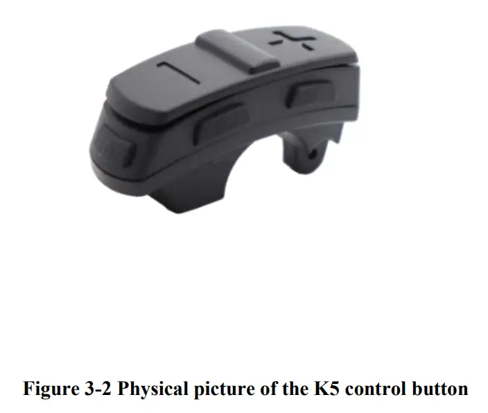
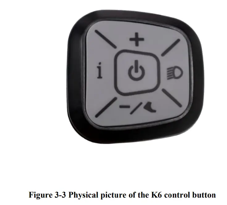
Functional areas
The YL91F-V display is equipped with five buttons on the corresponding operating unit: power on/off ![]() , plus
, plus ![]() ,minus
,minus ![]() , light
, light ![]() and toggle
and toggle ![]() .
.
Routine operation
Power on/off
Long press ![]() to power on/off the display. When the display is off, it will not use the battery power and the leakage current is less than 1uA.
to power on/off the display. When the display is off, it will not use the battery power and the leakage current is less than 1uA.
![]() The display will automatically shut off if it is not used for more than 10 minutes.
The display will automatically shut off if it is not used for more than 10 minutes.
Display interface switching
When the display is powered on, it will show the Current Speed (km/h) and Odometer (km) by default. Short press ![]() to switch between Odometer (km), Trip Odometer(km), Maximum Speed (km/h), and Average Speed (km/h).
to switch between Odometer (km), Trip Odometer(km), Maximum Speed (km/h), and Average Speed (km/h).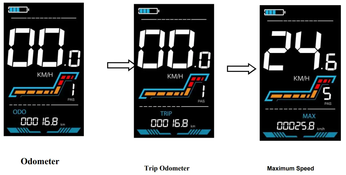
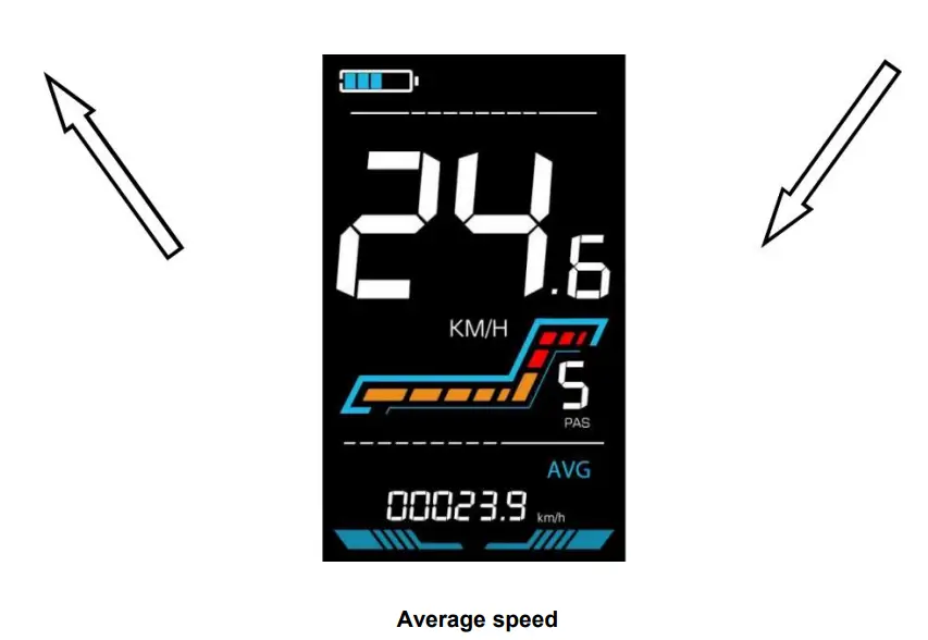
Figure 5-1 Display Interface Switching
Walk boost mode
Long Press and hold ![]() , the electric bicycle enters the walk boost mode. The electric bicycle will walk at a fixed speed of 6 km per hour and the display shows
, the electric bicycle enters the walk boost mode. The electric bicycle will walk at a fixed speed of 6 km per hour and the display shows ![]() state before walk boost. . Release the button to stop the power output immediately and restore to the state before walk boost.
state before walk boost. . Release the button to stop the power output immediately and restore to the state before walk boost.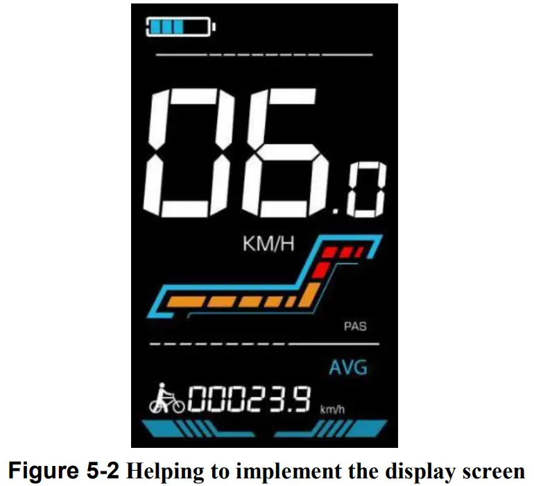
![]() The walk boost mode can only be used when pushing the electric bicycle, please do not use it while riding.
The walk boost mode can only be used when pushing the electric bicycle, please do not use it while riding.
Turning on/off lights
Press the ![]() to make the controller turn on the lights and the display backlight becomes dim. Press
to make the controller turn on the lights and the display backlight becomes dim. Press ![]() again to make the controller turn off the lights and the backlight restore brightness.
again to make the controller turn off the lights and the backlight restore brightness.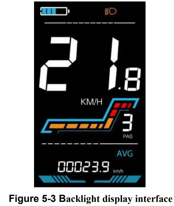
PAS level selection
Press ![]() /
/ ![]() to switch PAS level of electric bicycle, thus changing the motor output power.
to switch PAS level of electric bicycle, thus changing the motor output power.
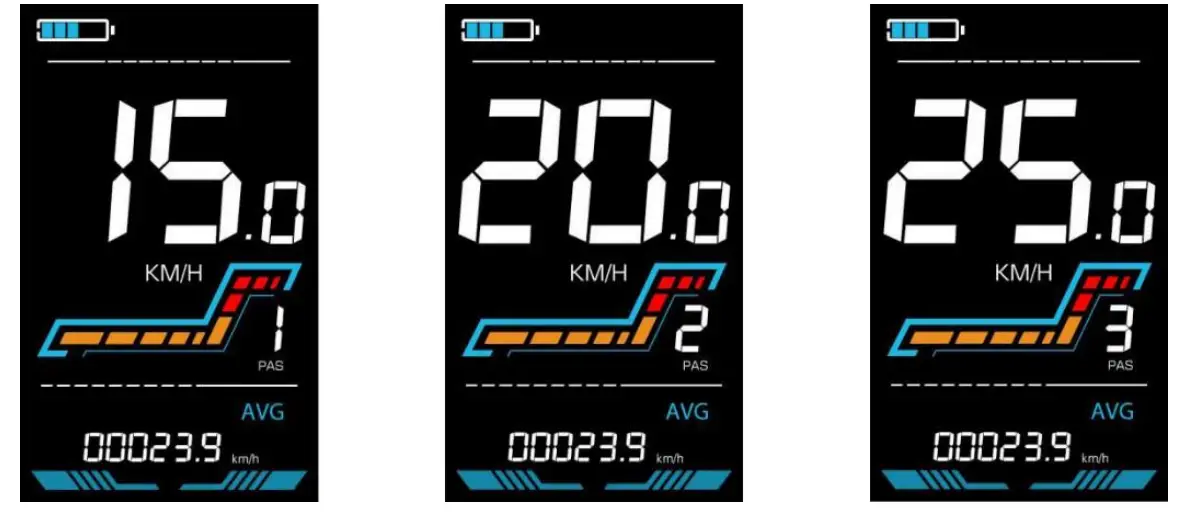
Figure 5-4 PAS level display interface
Battery level display
The Battery level is shown as 5 bars. When the battery is full charged, all of the 5 bars lighten up. When the battery is fully depleted, the bar will begin to flash, warning the user to charge the battery as soon as possible.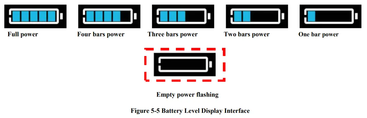
Error code display
If there is a fault occurs in the electronic system of the electric bicycle, the display will automatically show an error code, see Schedule 1 for a detailed definition of the error code.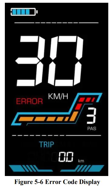
![]() When the error code appears on the display, please troubleshoot the problem in time, the electric bicycle will not be able to drive normally after the problem occurs.
When the error code appears on the display, please troubleshoot the problem in time, the electric bicycle will not be able to drive normally after the problem occurs.
Personalized parameter settings
![]() Each setting needs to be done with the bicycle stationary.
Each setting needs to be done with the bicycle stationary.
The personalized parameter setting procedure is as follows:
When the display is ON and the speed shows 0,
- Press and hold

 simultaneously for more than 2 seconds to enter the personalized parameter setting interface.
 - Press / changing state. to toggle between the personalized parameter setting interface, and press
 to enter the parameter
 - Press / to select the parameter, long pres for addition operation, long press for subtraction operation.
- Press to save the parameter settings and return to the personalized parameter setting interface.
- Long Press to save the parameter settings and exit the personalized parameter setting interface. The following options are available on the personalized parameter setting interface:
Metric and Imperial setting
P1 is the metric and imperial setting, 00 for metric and 01 for imperial.
Press to enter the parameter changing state. Press the ![]() /
/![]() to select the parameter and press
to select the parameter and press ![]() to save the parameter setting and return to the personalized parameter setting interface.
to save the parameter setting and return to the personalized parameter setting interface.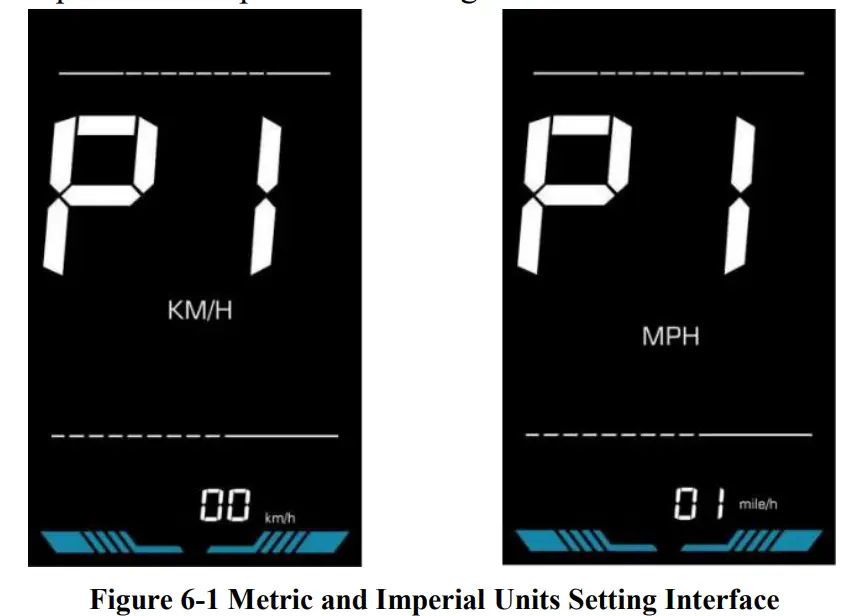
Rated voltage setting
P2 is the rated voltage setting. The available rated voltage range is: 24V, 36V, 48V, 52V.
Press ![]() to enter the parameter changing state. Press the
to enter the parameter changing state. Press the ![]() /
/ ![]() to select the parameter and press
to select the parameter and press ![]() to save the parameter setting and return to the personalized parameter setting interface.
to save the parameter setting and return to the personalized parameter setting interface.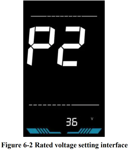
PAS level setting
P3 is the Pedal assist (PAS) level setting. The available Pedal assist level settings are: 0~3, 1~3, 0~5, 1~5, 1~7, 0~7, 0~9, 1~9.
Press ![]() to enter the parameter changing state. Press the
to enter the parameter changing state. Press the ![]() /
/ ![]() to select the parameter and press to save the parameter setting and return to the personalized parameter setting interface.
to select the parameter and press to save the parameter setting and return to the personalized parameter setting interface.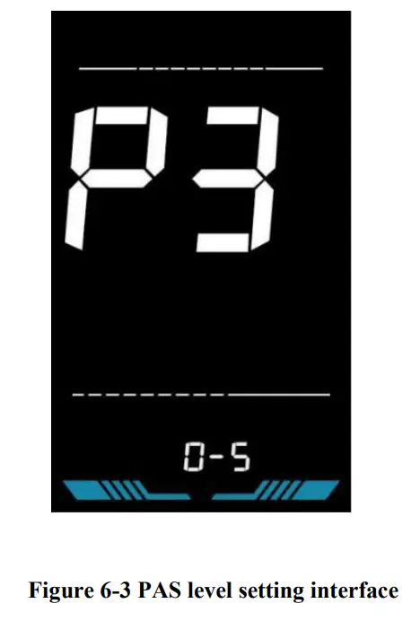
Wheel diameter setting
P4 is the wheel diameter setting. The adjustable wheel diameter range is: 1~50inch.
Press ![]() to enter the parameter changing state. Press the
to enter the parameter changing state. Press the ![]() /
/![]() to select the parameter and press
to select the parameter and press ![]() to save the parameter setting and return to the personalized parameter setting interface.
to save the parameter setting and return to the personalized parameter setting interface.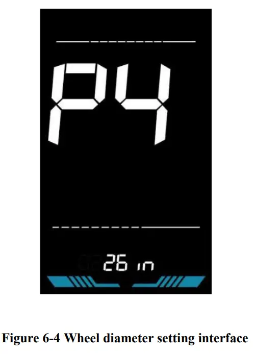
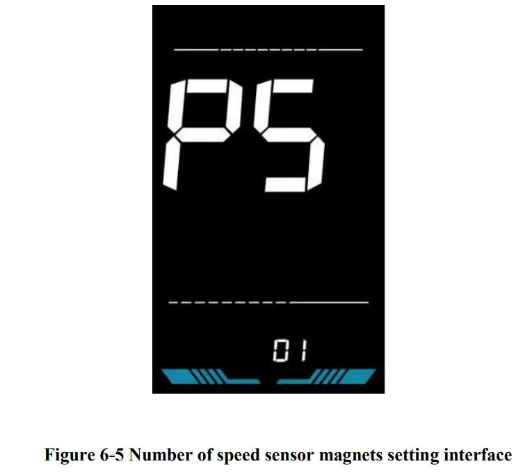
Number of speed sensor magnets setting
P5 is the speed sensor magnet number setting. The adjustable speed sensor magnet number range is: 1 ~ 100 pcs.
Press ![]() to enter the parameter changing state. Press the
to enter the parameter changing state. Press the ![]() /
/![]() to select the parameter and press
to select the parameter and press ![]() to save the parameter setting and return to the personalized parameter setting interface.
to save the parameter setting and return to the personalized parameter setting interface.
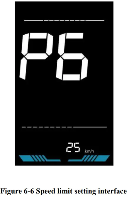
Speed Limit Setting
P6 is the speed limit setting. The adjustable speed limit range is: 1~100km/h. (The maximum adjustable speed limit varies by different protocols)
Press ![]() to enter the parameter changing state. Press the
to enter the parameter changing state. Press the ![]() /
/![]() to select the parameter and press
to select the parameter and press ![]() to save the parameter setting and return to the personalized parameter setting interface.
to save the parameter setting and return to the personalized parameter setting interface.
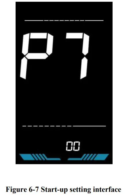
Start-up setting
P7 is the start-up setting. The display can choose the following start modes: 00zero start, 01non-zero start.
Press ![]() to enter the parameter changing state. Press the
to enter the parameter changing state. Press the ![]() /
/![]() to select the parameter and press
to select the parameter and press ![]() to save the parameter setting and return to the personalized parameter setting interface.
to save the parameter setting and return to the personalized parameter setting interface.
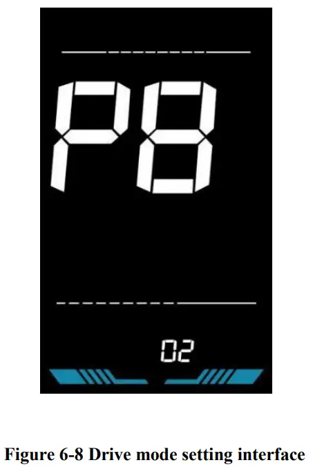
Drive mode setting
P8 is the drive mode setting. The available drive modes are: 00→Pedal assist only, 01→Electric only, 02→Both Pedal assist and electric.
Press ![]() to enter the parameter changing state. Press the
to enter the parameter changing state. Press the ![]() /
/![]() to select the parameter and press to save the parameter setting and return to the personalized parameter setting interface.
to select the parameter and press to save the parameter setting and return to the personalized parameter setting interface.
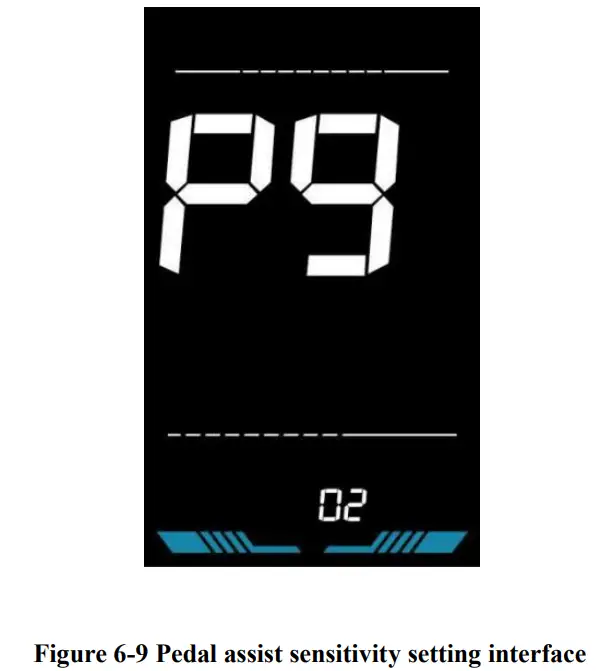
Pedal assist sensitivity setting
P9 is the pedal assist sensitivity setting. When set to higher numbers, it will take more crank rotations to activate the motor. On lower numbers, it will take little crank rotation to activate the motor. The adjustable range is: 1~24.
Press ![]() to enter the parameter changing state. Press the
to enter the parameter changing state. Press the ![]() /
/![]() to select the parameter and press
to select the parameter and press ![]() to save the parameter setting and return to the personalized parameter setting interface.
to save the parameter setting and return to the personalized parameter setting interface.
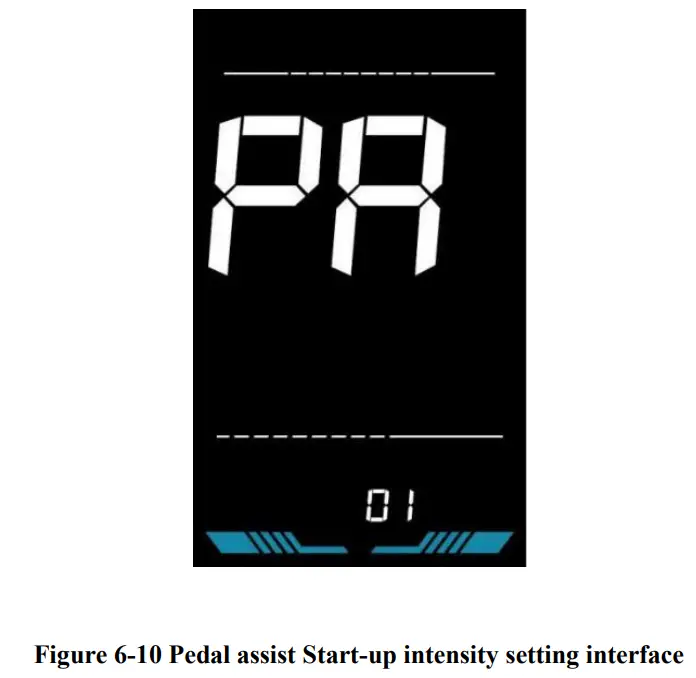
Pedal assist strength setting
PA is the Pedal assist strength setting. The Pedal assist strength is the relative strength of the PWM signal from the controller when start to activate pedal assist. The adjustable range is 0 ~ 5. 0 is the weakest strength and 5 is the strongest.
Press ![]() to enter the parameter changing state. Press the
to enter the parameter changing state. Press the ![]() /
/![]() to select the parameter and press
to select the parameter and press ![]() to save the parameter setting and return to the personalized parameter setting interface.
to save the parameter setting and return to the personalized parameter setting interface.
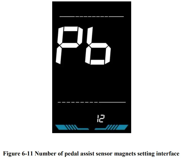
Number of pedal assist sensor magnets setting
Pb is the number of pedal assist sensor magnets setting. The adjustable range: 1~15 pcs.
Press ![]() to enter the parameter changing state. Press the
to enter the parameter changing state. Press the ![]() /
/![]() to select the parameter and
to select the parameter and ![]() press parameter setting and return to the personalized parameter setting interface.
press parameter setting and return to the personalized parameter setting interface.
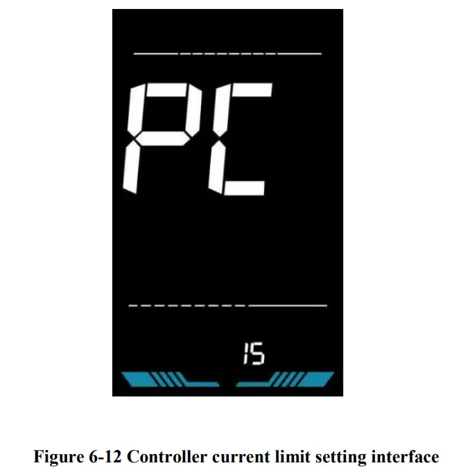
Controller Current Limit Setting
PC is the controller current limit setting. The adjustable range is: 1~50A.
Press ![]() to enter the parameter changing state. Press the
to enter the parameter changing state. Press the ![]() /
/![]() to select the parameter and press
to select the parameter and press ![]() to save the parameter setting and return to the personalized parameter setting interface.
to save the parameter setting and return to the personalized parameter setting interface.
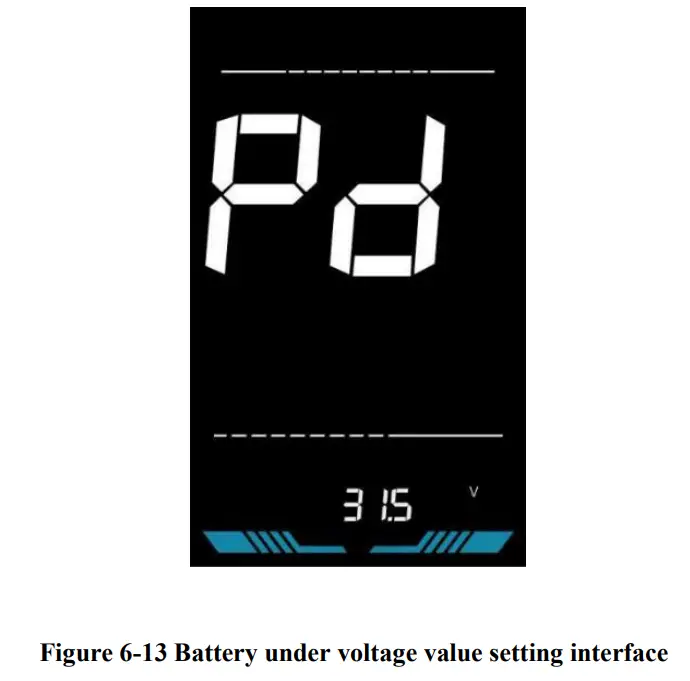
Battery under voltage value setting
Pd is the battery under voltage setting. The value can be adjusted based on the current rated voltage.
Press ![]() to enter the parameter changing state. Press the
to enter the parameter changing state. Press the ![]() /
/![]() to select the parameter and press
to select the parameter and press ![]() to save the parameter setting and return to the personalized parameter setting interface.
to save the parameter setting and return to the personalized parameter setting interface.
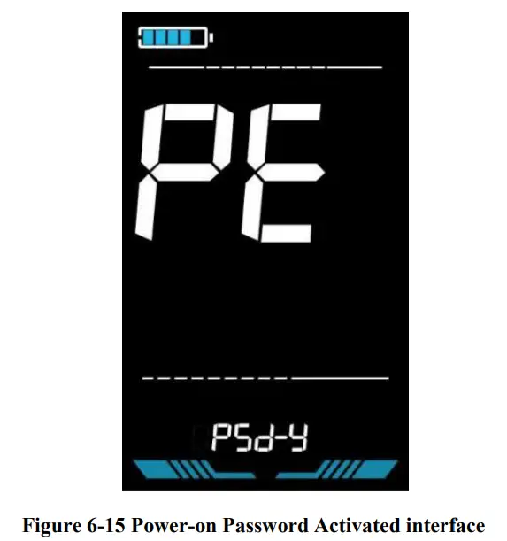
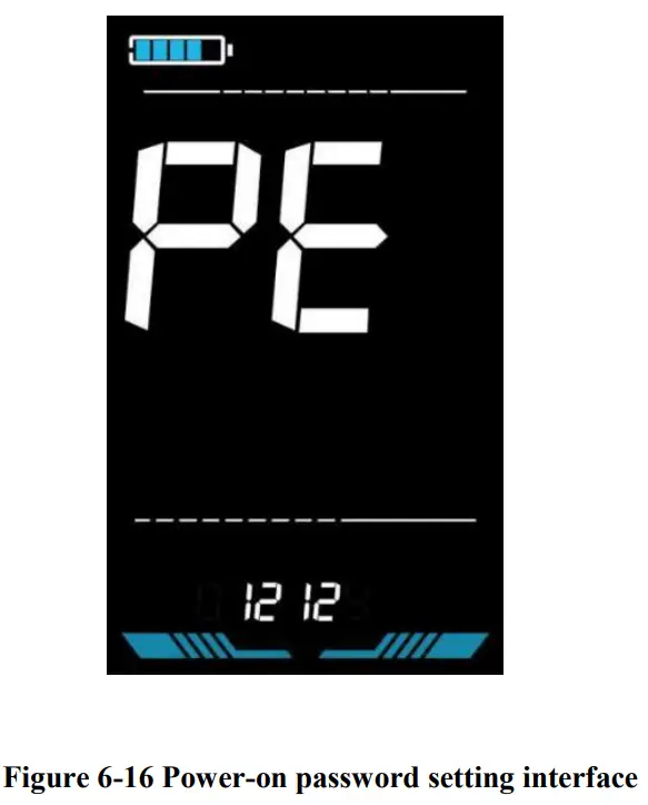
Power-on password setting
PE is the power-on password setting. The power-on password is not activated by default but users can activate it from setting PSd-y. The factory default password is 1212. Users can set other four-digit password. Please keep the password in mind after changing it, otherwise you will not be able to use the display.
Press ![]() to enter the parameter changing state. Press the
to enter the parameter changing state. Press the ![]() /
/![]() to select the parameter. PSd-y means the power-on password is activated while PSd-n is off. Press
to select the parameter. PSd-y means the power-on password is activated while PSd-n is off. Press ![]() to confirm the mode and enter the state of setting the four digits power-on password or exit to the personalized parameter setting interface.
to confirm the mode and enter the state of setting the four digits power-on password or exit to the personalized parameter setting interface.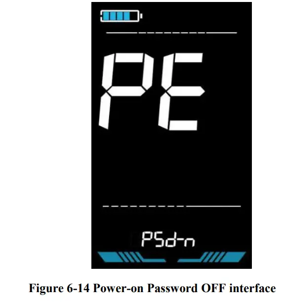
In the password setting mode, the adjustable digit will flash. Press the ![]() /
/![]() to select the parameter and press
to select the parameter and press ![]() to save the numbers and go to the next digit setting. Long press
to save the numbers and go to the next digit setting. Long press ![]() to save the parameter setting and return to the personalized parameter setting interface after finishing setting the four digits in turn.
to save the parameter setting and return to the personalized parameter setting interface after finishing setting the four digits in turn.
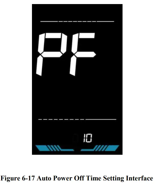
Auto Sleep Time Setting
PF is the auto sleep time setting. To save the battery power and reach higher range, this display will be turned off after it has not been used for a time. The adjustable range is: 1~60min, 00 means no auto shutdown. The factory default setting is 10 minutes.
Press ![]() to enter the parameter changing state. Press the
to enter the parameter changing state. Press the ![]() /
/![]() to select the parameter and press
to select the parameter and press ![]() to save the parameter setting and return to the personalized parameter setting interface.
to save the parameter setting and return to the personalized parameter setting interface.
Shortcut operation
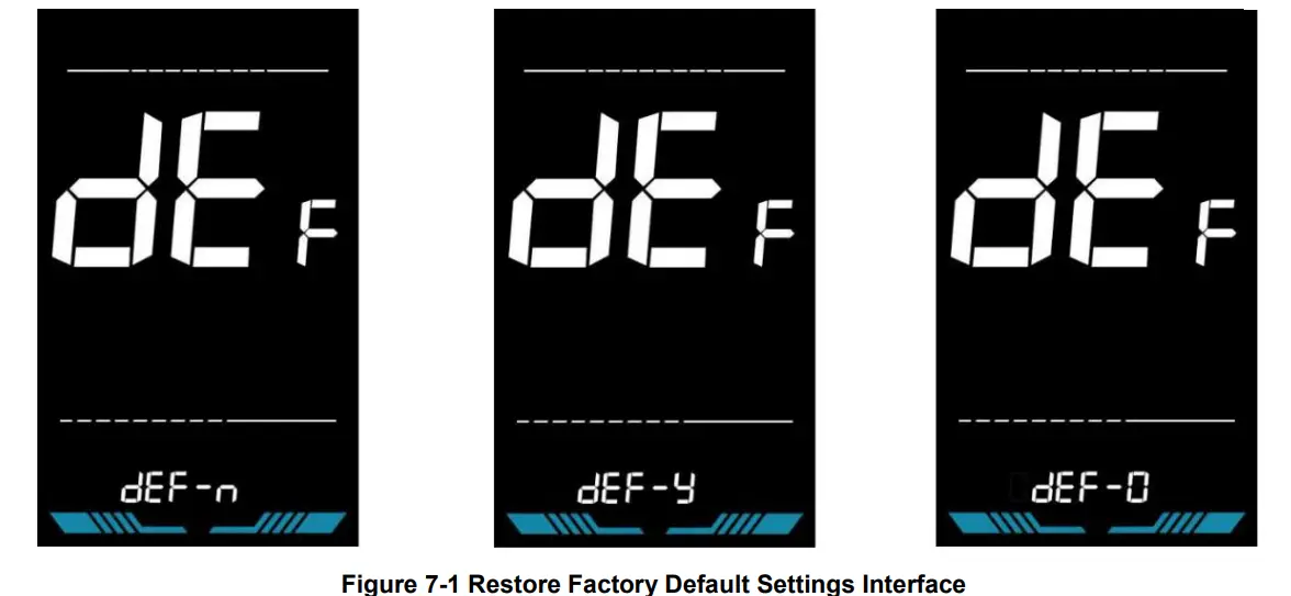
Restore factory settings operation
dEF is the restore factory default parameter settings. dEF-Y is to restore the factory default settings, and dEF-N is not to restore.
Enter into the main setting interface and keep the speed at 0, press and hold ![]() and
and ![]() simultaneously for 2s to enter the restore factory default setting interface. Pressing
simultaneously for 2s to enter the restore factory default setting interface. Pressing ![]() /
/![]() to toggle to dEF-Y. Then after pressing
to toggle to dEF-Y. Then after pressing ![]() to confirm, the display will show dEF-0 for a few seconds and then automatically start to restore the factory default settings. The display will automatically exit to setting interface after the restoration.
to confirm, the display will show dEF-0 for a few seconds and then automatically start to restore the factory default settings. The display will automatically exit to setting interface after the restoration.
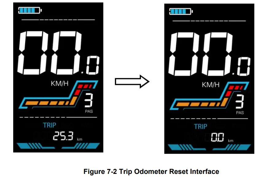
Trip odometer reset operation
The display can record trip odometer and odometer. Trip odometer is not automatically reset after turning off. The trip odometer needs to be reset manually. The odometer can not be reset.
Enter into the main setting interface and keep the speed at 0, press and hold ![]() and
and ![]() simultaneously for 2s to reset the trip odometer. The main interface will flash during the reset process.
simultaneously for 2s to reset the trip odometer. The main interface will flash during the reset process.
Quality Assurance and Warranty
Warranty info
- Yolin will offer a limited warranty for any failure caused by the product defects under normal use during the warranty period.
Warranty does not cover
- The shell is opened.
- The connector is damaged.
- Scratches on the appearance after the product is out of factory.
- Scratched or broken wires
- Failure or damage caused by force majeure (e.g. fire, earthquake, etc.) or natural disaster (e.g. lightning strike, etc.)
- Out of warranty period.
Wire connection diagram
Standard wire connection sequence
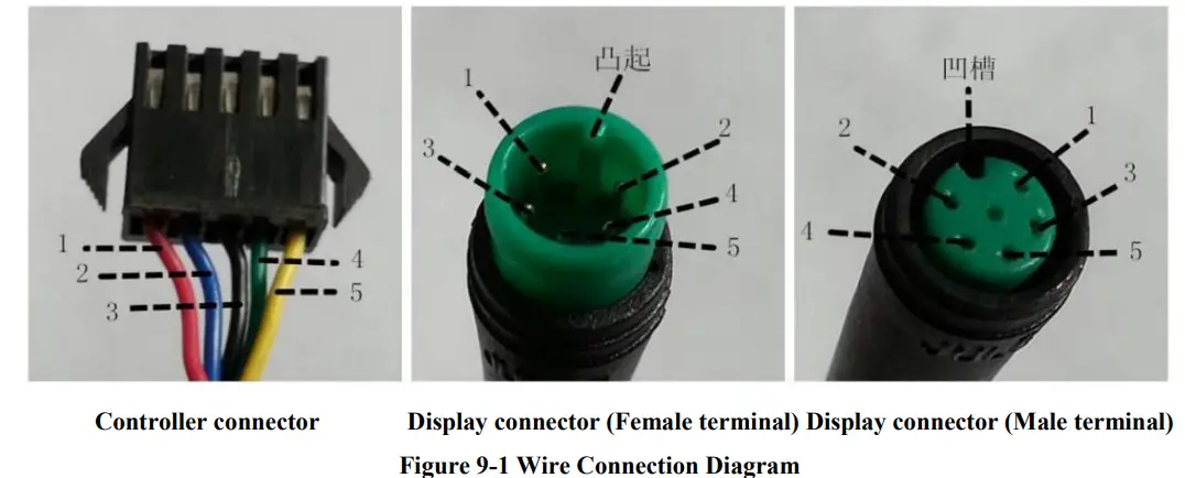
Table 9-1 Standard connector wire sequence table
Standard Wire Sequence | Standard wire color | Function |
| 1 | Red (VCC) | Display power wire |
| 2 | Blue (Kp) | Controller power wire |
| 3 | Black (GND) | Display ground wire |
| 4 | Green (RX) | Display data reception wire |
| 5 | Yellow (TX) | Display data transmit wire |
- Some models are equipped with waterproof connectors and the color inside wires can not be seen.
Precautions
Pay attention to all the general operating when using the products and do not plug and unplug the display while it is powered on.
- Avoid bumping the display as much as possible.
- Please do not change the parameter settings at will, otherwise normal riding cannot be guaranteed.
- If display does not work properly, please send it to the repair center as soon as possible.
- There may be differences between the physical products and this manual due to normal upgrade. Please refer to the physical products.
Schedule 1: Error Code Definition
YL-01, YL-02 Error codes | ||||
| Error code | Definition | Error code | Definition | |
| E001 | Controller failure | E004 | Throttle failure | |
| E002 | Communication failure breakdown | E005 | Brake failure | |
| E003 | Hall failure | E006 | Motor phase failure | |
YL-05, KDS, YL-J Error codes | ||||
| Error code | Definition | Error code | Definition | |
| E021 | Current failure | E024 | Hall failure | |
| E022 | Throttle failure | E025 | Brake failure | |
| E023 | Motor phase failure | E030 | Communication failure | |
Schedule 2: Pedal assist level default ratio value
| Level Level selection | 1 | 2 | 3 | 4 | 5 | 6 | 7 | 8 | 9 |
| 0-3/1-3 | 50% | 74% | 92% | – | – | – | – | – | – |
| 0-5/ 1-5 | 50% | 61% | 73% | 85% | 96% | – | – | – | – |
| 0-7/ 1-7 | 40% | 50% | 60% | 70% | 80% | 90% | 96% | – | – |
| 0-9/ 1-9 | 25% | 34% | 43% | 52% | 61% | 70% | 79% | 88% | 96% |
Email: [email protected]
Website: www.cmacewheel.com