Yolin YL80C E-Bike Display
Yolin YL80C E-Bike Display
YL80C-Bike Display
User Manual
Product name and model
Intelligent LCD display for e-bike; model: YL80C.
Specifications
- 36V/48V power supply
- Rated working current 15mA
- Maximum working current 30mA
- Leakage current at power-off <1uA
- Working current at the supply controller end 50mA
- Working temperature -20~60
- Storage temperature -30~70
Appearance and dimensions
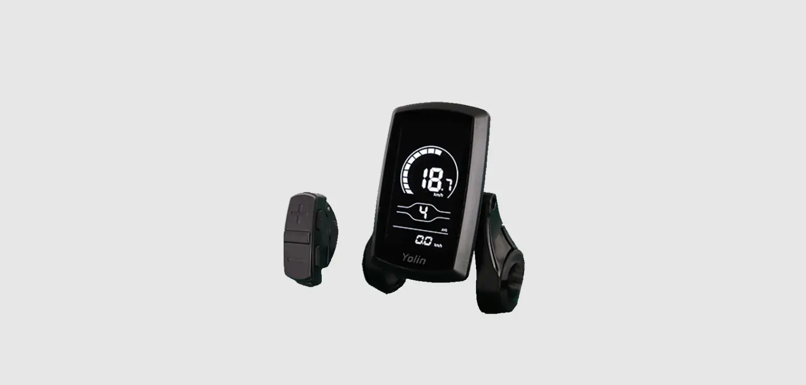
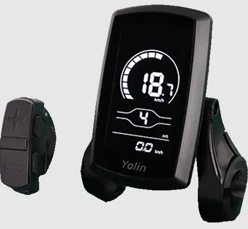
 Fig. 3-1 Picture of Display 80C
 Fig. 3-2 Picture of Display 80C Buttons
 Fig. 3-3 Front View of Display 80C Dimensions
 Fig. 3-4 Side View of Display 80C Dimensions
Function overview and the functional area layout
Function overview
- Display YL80C provides a variety of functions to meet your riding needs, including:
- Battery level indicator
- Motor power indicator
- Assist level adjustment and indication
- Speed indicator (including real-time speed, maximum speed, and average speed)
- Distance indicator (including trip distance and ODO)
- Push assistance control and indication
- Headlight control and indication
- Error code indicator
- USB connection indicator (reserved)
- Heart rate indicator (reserved)
- Bluetooth connection indicator (reserved)
- Custom parameter setting (e.g., wheel diameter, speed limit, battery level, assist level, power-on password,controller current limit, etc.)
- Reset function
Functional area layout
Fig. 4-1 Functional Area Layout Interface of Display YL80C
There are five buttons on the operating unit of display YL80C, i.e., the on/off button ![]() plus button
plus button ![]() , minus button
, minus button ![]() , headlight button
, headlight button ![]() , and switching button
, and switching button ![]() .
.
General operation
Power on/off
By pressing and holding the button ![]() , the display will start to work and the working power supply of the controller will be turned on. In the power-on state, by pressing the button
, the display will start to work and the working power supply of the controller will be turned on. In the power-on state, by pressing the button ![]() , your e-bike will be powered off. In the power-off state, the display will no longer use the battery power, and its leakage current will be less than 1uA. If your e-bike is not used for more than 10 minutes, the display will be automatically powered off.
, your e-bike will be powered off. In the power-off state, the display will no longer use the battery power, and its leakage current will be less than 1uA. If your e-bike is not used for more than 10 minutes, the display will be automatically powered off.
Display interface
After the display is turned on, the display will show the real-time speed (km/h) and the trip distance (km) by default.
By pressing the button ![]() , the information displayed will be switched between the trip distance (km), ODO (km), maximum speed (km/h), average speed (km/h), and riding power.
, the information displayed will be switched between the trip distance (km), ODO (km), maximum speed (km/h), average speed (km/h), and riding power.
Push assistance
By pressing and holding the button ![]() , the electric push assistance mode will be enabled. Your e-bike will run at a constant speed of 6km/h. The display will show
, the electric push assistance mode will be enabled. Your e-bike will run at a constant speed of 6km/h. The display will show ![]() . By releasing the button
. By releasing the button ![]() , your e-bike will immediately stop power output and return to the state before push assistance.
, your e-bike will immediately stop power output and return to the state before push assistance. Fig. 5-2 Push Assistance Indicator Interface
![]() The push assistance function can only be used when you are pushing your e-bike. Please do not use it during riding.
The push assistance function can only be used when you are pushing your e-bike. Please do not use it during riding.
Headlight on/off
By pressing the button ![]() , the controller will turn on the headlights and the display backlight will turn dark; by pressing the button
, the controller will turn on the headlights and the display backlight will turn dark; by pressing the button ![]() again, the controller will turn off the headlights and the display backlight will resume its luminance.
again, the controller will turn off the headlights and the display backlight will resume its luminance. 
Fig. 5-3 Backlight-on Indication Interface
Assist level selection
By pressing the button ![]() /
/ ![]() , the e-bike assists level will be switched to change the motor output power.
, the e-bike assists level will be switched to change the motor output power. 
Battery level indicator
The battery level indicator consists of five segments. When the battery is fully charged, the five segments will be all on.
In the case of Undervoltage, the outline of the battery indicator will flash, which means the battery has to be charged immediately.
Fig. 5-5 Battery Level Indicator Interface
Motor power indicator
The display can indicate the output power of the motor, as shown in the figure below.
Fig. 5-6 Motor Power Indicator Interface
Error code indicator
When a fault occurs in the electronic control system of your e-bike, the display will automatically indicate the error code. Detailed definitions of error codes are shown in Schedule 1. 
Fig. 5-7 Error Code Indicator Interface![]() When an error code appears on the display interface, please conduct troubleshooting in time. Otherwise, your e-bike will not work normally.
When an error code appears on the display interface, please conduct troubleshooting in time. Otherwise, your e-bike will not work normally.
General setting
![]() All parameters can only be set when your e-bike stops.
All parameters can only be set when your e-bike stops.
The steps for the general setting are as follows:
In the power-on state, when the display shows the speed of 0,
- Press and hold the buttons
 and
and  at the same time for more than 2 seconds to enter the selection interface of general setting options;
 - Press the button / to switch the selection interface of general setting options, and press the button
 to enter the parameter modification interface;
 - Press the button / for parameter selection;
- Press the button to save the parameter and return to the selection interface of general setting options;
- Press and hold the button to save the parameter and exit the selection interface of general setting options.
The following selection interfaces of general setting options are available:
Trip distance reset
TC refers to the trip distance reset of the item. TC-n means not to reset the trip distance, and tC-y means to reset the trip distance.
Press the button ![]() to enter the parameter modification interface. Press the button
to enter the parameter modification interface. Press the button ![]() /
/ ![]() for parameter selection.
for parameter selection.
Press the button ![]() to save the parameter and return to the selection interface of general setting options.
to save the parameter and return to the selection interface of general setting options.
Fig. 6-1 Trip Distance Reset Interface
6.2 Backlight luminance setting
bL refers to the backlight luminance setting option. Parameters bL-1, bL-2 and bL-3 are available, which represent the backlight luminance, 1 for the minimum luminance, 2 for the standard luminance, and 3 for the maximum luminance.
Press the button ![]() to enter the parameter modification interface. Press the button
to enter the parameter modification interface. Press the button ![]() /
/![]() for parameter selection.
for parameter selection.
Press the button ![]() to save the parameter and return to the selection interface of general setting options.
to save the parameter and return to the selection interface of general setting options. 
Fig. 6-2 Backlight Luminance Setting Interface
Metric/imperial system setting
Un refers to the metric/imperial system setting option. U-1 represents the imperial system, and U-2 represents the metric system.
Press the button ![]() to enter the parameter modification interface. Press the button
to enter the parameter modification interface. Press the button ![]() /
/![]() for parameter selection.
for parameter selection.
Press the button ![]() to save the parameter and return to the selection interface of general setting options.
to save the parameter and return to the selection interface of general setting options.
Fig. 6-3 Imperial System Setting Interface
Fig. 6-4 Metric System Setting Interface
General parameter setting
The steps for general parameter setting are as follows:
In the power-on state, when the display shows the speed of 0,
- Press and hold the buttons / at the same time for more than 2 seconds to enter the selection interface of the general setting options;
- Press and hold the buttons and at the same time for more than 2 seconds to enter the selection interface of general parameter setting options;
- Press the button / to switch the function, and press the button to enter the parameter modification interface;
- Press the button / for parameter selection;
- Press the button to save the parameter and enter the next selection interface of general parameter setting options;
- Press and hold the button to save the parameter and exit the selection interface of general parameter setting options.
Wheel diameter setting
Ld refers to the wheel diameter setting option. Available parameters include: 8-26, 700C, 28-30 inches.
Press the button ![]() to enter the parameter modification interface. Press the button
to enter the parameter modification interface. Press the button ![]() /
/![]() to select the wheel diameter corresponding to your e-bike (to ensure the accuracy of the speed and distance indication of the display). Press the button
to select the wheel diameter corresponding to your e-bike (to ensure the accuracy of the speed and distance indication of the display). Press the button ![]() to save the parameter and enter the next selection interface of general parameter setting options.
to save the parameter and enter the next selection interface of general parameter setting options.
Fig. 7-1 Wheel Diameter Setting Interface
Speed limit setting
LS refers to the speed limit setting option. By modifying this value, you can set the maximum riding speed of your e-bike. The selectable range of the maximum speed setting value is 12km/h-40km/h.
Press the button ![]() to enter the parameter modification interface. Press the button
to enter the parameter modification interface. Press the button ![]() /
/![]() to select the maximum riding speed. Press the button
to select the maximum riding speed. Press the button ![]() to save the parameter and enter the next selection interface of general parameter setting options.
to save the parameter and enter the next selection interface of general parameter setting options.
Fig. 7-2 Speed Limit Setting Interface
Custom setting
In order to meet the individual requirements of customers, custom setting options are available, including battery level setting of the display, assistance parameter setting, current limit setting, assistance sensor setting, speed sensor setting, handlebar function setting, system setting, and power-on password setting, totally eight setting options. Not all protocols support the custom setting options of display YL80C. Some protocols only support part of the setting options. 
Fig. 8-1 Selection Interface of Custom Setting Options
The steps for custom setting are as follows: in the power-on state, when the display shows the speed of 0,
- Press and hold the buttons and at the same time for more than 2 seconds to enter the selection interface of general setting options;
- Press and hold the buttons and at the same time for more than 2 seconds to enter the selection interface of custom setting options;
- Press the button / to switch the function, and press the button to enter the parameter modification interface;
- Press the button / for parameter selection;
- Press the button to save the parameter and enter the next parameter setting interface, or press and hold the button to save the parameter and return to the selection interface of custom setting options; or press and hold the button for more than 2 seconds to cancel the current operation without saving the current data and return to the selection interface of custom setting options;
- Press and hold the button to save the parameter and exit the selection interface of custom setting options.
![]() If no operations are performed within one minute, the display will automatically exit the setting interface.
If no operations are performed within one minute, the display will automatically exit the setting interface.
Battery level setting
VOL refers to the battery level setting option. You’ll be required to input the voltage values of sections 1-5 one by one.
Press the button ![]() to enter the parameter modification interface. Take the first battery level value of 36V as an example. “1” shown on the display means the first voltage value, and “31.5” means the first battery level value. Press the button
to enter the parameter modification interface. Take the first battery level value of 36V as an example. “1” shown on the display means the first voltage value, and “31.5” means the first battery level value. Press the button ![]() /
/![]() to change the value, and press the button
to change the value, and press the button ![]() to confirm the setting and enter the battery level parameter setting interface of the next section. After the 5 battery level values are all set, press the button
to confirm the setting and enter the battery level parameter setting interface of the next section. After the 5 battery level values are all set, press the button ![]() to confirm the settings and return to the selection interface of custom setting options.
to confirm the settings and return to the selection interface of custom setting options.
Fig. 8-2 Battery Level Setting Interface
Assistance parameter setting (option)
SCR refers to the assistance parameter setting option. Press the button ![]() to enter the parameter modification interface.
to enter the parameter modification interface.
8.2.1 Assist level selection
The assist levels available for the display include: levels 0-3, levels 1-3, levels 0-5, levels 1-5, levels 0-7, levels 1-7, levels 0-9, and levels 1-9.
Press the button ![]() /
/![]() to switch the level. Press the button
to switch the level. Press the button ![]() to confirm the level mode and enter the 8.2.2 assistance ratio setting option, or press and hold the button
to confirm the level mode and enter the 8.2.2 assistance ratio setting option, or press and hold the button ![]() to confirm the setting and return to the selection interface of custom setting options.
to confirm the setting and return to the selection interface of custom setting options.
Fig. 8-3 Assist Level Selection Interface
8.2.2 Assistance ratio setting option
By setting the assistance ratio, the speed of each level can be adjusted to meet the needs of different cyclists. Refer to Schedule 2 for details.
Taking level 1 as an example, “45-55%” refers to the assistance ratio range of level 1, and “50%” is the default value of level 1, which is adjustable.
Press the button ![]() /
/![]() to modify the parameter. Press the button
to modify the parameter. Press the button ![]() to confirm the setting and enter the parameter setting interface of the next level. After the parameters of all levels are set, press the button
to confirm the setting and enter the parameter setting interface of the next level. After the parameters of all levels are set, press the button ![]() again to return to the selection interface of custom setting options.
again to return to the selection interface of custom setting options.
Fig. 8-4 Assistance Ratio Setting Interface
Current limit setting
CUr refers to the current limit setting option. The current limit can be set in the range of 7.0-25.0A.
Press the button ![]() to enter the parameter modification interface. Press the button
to enter the parameter modification interface. Press the button ![]() /
/![]() for parameter selection. Modify the maximum current of the controller and press the button
for parameter selection. Modify the maximum current of the controller and press the button ![]() to save the setting and return to the selection interface of custom setting options.
to save the setting and return to the selection interface of custom setting options.
Fig. 8-5 Current Limit Setting Interface
Assistance sensor setting (option)
PAS refers to the assistance sensor setting option. Press the button ![]() to enter the parameter modification interface.
to enter the parameter modification interface.
8.4.1 Assistance sensor direction setting
run refers to the assistance sensor direction setting option. Run-F/b is displayed on the screen. run-F represents the forward direction, and run-b represents the backward direction.
Press the button ![]() /
/![]() to select an assistance sensor direction. Press the button
to select an assistance sensor direction. Press the button ![]() to confirm the parameter and enter the 8.4.2 assistance sensor sensitivity setting option, or press and hold the button
to confirm the parameter and enter the 8.4.2 assistance sensor sensitivity setting option, or press and hold the button ![]() to confirm the parameter and return to the selection interface of custom setting options.
to confirm the parameter and return to the selection interface of custom setting options.
Fig. 8-6 Assistance Sensor Direction Setting Interface
8.4.2 Assistance sensor sensitivity setting
SCN refers to the assistance sensor sensitivity setting option. The setting range is 2-9, where 2 means the maximum sensitivity and 9 means the minimum sensitivity.
Press the button ![]() /
/![]() to select the assistance sensor sensitivity. Press the button
to select the assistance sensor sensitivity. Press the button ![]() to confirm the parameter and enter the 8.4.3 steel magnet number setting option for assistance magnetic disk, or press and hold the button
to confirm the parameter and enter the 8.4.3 steel magnet number setting option for assistance magnetic disk, or press and hold the button ![]() to confirm the parameter and return to the selection interface of custom setting options.
to confirm the parameter and return to the selection interface of custom setting options.
Fig. 8-7 Assistance sensor sensitivity setting interface
8.4.3 Steel magnet number setting for assistance magnetic disk
n- refers to the steel magnet number setting option for assistance magnetic disk. The setting range is 5-9, 12, and 24.
Press the button ![]() /
/![]() to select the corresponding number of steel magnets for assistance, and press the button
to select the corresponding number of steel magnets for assistance, and press the button ![]() to confirm the parameter and return to the selection interface of custom setting options.
to confirm the parameter and return to the selection interface of custom setting options.
Fig. 8-8 Steel Magnet Number Setting Interface for Assistance Magnetic Disk
Speed sensor setting
SPS refers to the speed sensor setting option, which can be set according to the number of magnetic heads installed on the wheels of your e-bike. The setting range is 1-15. Press the button ![]() to enter the parameter modification interface. Press the button
to enter the parameter modification interface. Press the button ![]() /
/![]() for parameter selection. Press the button
for parameter selection. Press the button ![]() to confirm the parameter and return to the selection interface of custom setting options.
to confirm the parameter and return to the selection interface of custom setting options.
Fig. 8-9 Steel Magnet Selection Interface for Speed Sensor
Handlebar function setting (option)
Hnd refers to the handlebar function setting option. Press the button ![]() to enter the parameter modification interface.
to enter the parameter modification interface.
8.6.1 Handlebar push assistance enables setting
HL refers to the handlebar push assistance enabling the setting. HL-N means that the push assistance function of the handlebar is enabled, and HL-Y means that the same is disabled, which means by turning the handlebar, the push assistance mode will be on.
Press the button ![]() /
/![]() to select a parameter. If you select HL-Y, press the button
to select a parameter. If you select HL-Y, press the button ![]() to confirm the parameter and return to the selection interface of custom setting options. If you select HL-N, press the button
to confirm the parameter and return to the selection interface of custom setting options. If you select HL-N, press the button ![]() to confirm the parameter and enter the 8.6.2 handlebar assist level enable setting option, or press and hold the button
to confirm the parameter and enter the 8.6.2 handlebar assist level enable setting option, or press and hold the button ![]() to confirm the parameter and return to the selection interface of custom setting options.
to confirm the parameter and return to the selection interface of custom setting options.
Fig. 8-10 Handlebar Push Assistance Setting Interface
8.6.2 Handlebar assist level enables setting
HF-Y refers to the handlebar assist level enabling the option. HF-N means that the assist level function of the handlebar is disabled. If HF-Y is selected, it means that when you turn the handlebar, the maximum speed can only reach the value corresponding to the assist level shown on the display. If HF-N is selected, it means that when you turn the handlebar, your e-bike can reach the rated maximum speed without being restricted by the assist level shown on the display.
Press the button ![]() /
/![]() to select the handlebar assists level status, and press the button
to select the handlebar assists level status, and press the button ![]() to confirm the parameter and return to the selection interface of custom setting options.
to confirm the parameter and return to the selection interface of custom setting options. 
Fig. 8-11 Handlebar Assist Level Enable Setting Interface
System setting (option)
SYS refers to the system setting option. Press the button ![]() to enter the parameter modification interface.
to enter the parameter modification interface.
8.7.1 Battery delay time setting
dLY refers to the battery delay time setting option. There are 3 parameters available for the battery delay time: 3s/6s/12s. Press the button ![]() /
/![]() for parameter selection.
for parameter selection.
Press the button ![]() to confirm the parameter and enter the 8.7.2 button push assistance to enable the setting option, or press and hold the button
to confirm the parameter and enter the 8.7.2 button push assistance to enable the setting option, or press and hold the button ![]() to confirm the parameter and return to the selection interface of custom setting options.
to confirm the parameter and return to the selection interface of custom setting options.
Fig. 8-12 Battery Delay Time Selection Interface
8.7.2 Button push assistance enables setting
PUS refers to the button push assistance that enables the setting interface. Y represents enable and N represents disable.
Press the button ![]() /
/![]() for parameter selection, and press the button
for parameter selection, and press the button ![]() to confirm the parameter and return to the selection interface of custom setting options.
to confirm the parameter and return to the selection interface of custom setting options.
Fig. 8-13 Button Push Assistance Enable Setting Interface
Power-on password setting (option)
PSd refers to the power-on password setting option.
P2 represents the power-on password setting option. The default power-on password is 1212. Press the button ![]() to enter the power-on password setting interface. Press the button
to enter the power-on password setting interface. Press the button ![]() /
/![]() for parameter selection, and press the button
for parameter selection, and press the button ![]() to move the cursor. After the 4-digit password is input, press the button
to move the cursor. After the 4-digit password is input, press the button ![]() to confirm the parameter. If the password is correct, the display will enter the 8.8.1 power-on password enable setting option; otherwise, it will stay in the password input interface.
to confirm the parameter. If the password is correct, the display will enter the 8.8.1 power-on password enable setting option; otherwise, it will stay in the password input interface.
Fig. 8-14 Power-on Password Input Setting Interface
8.8.1 Power-on password enable setting
By inputting the password, you can enter the password and enable the setting option. PSd-Y means that a power-on password is required, and PSd-N means that no power-on passwords are required.
Press the button ![]() /
/![]() for parameter selection.
for parameter selection.
If you select PSd-N, press the button ![]() to confirm the parameter and return to the selection interface of custom setting options. If you select PSd-Y, press the button
to confirm the parameter and return to the selection interface of custom setting options. If you select PSd-Y, press the button ![]() to enter the 8.8.2 power-on password modification setting option, or press and hold the button
to enter the 8.8.2 power-on password modification setting option, or press and hold the button ![]() to confirm the parameter and return to the selection interface of custom setting options.
to confirm the parameter and return to the selection interface of custom setting options. 
Fig. 8-15 Password Enable Confirmation Interface
8.8.2 Power-on password modification setting
P3 refers to the power-on password modification setting option. Press the button ![]() for cursor movement and the button
for cursor movement and the button ![]() /
/![]() for parameter selection. After the modification, press and hold the button
for parameter selection. After the modification, press and hold the button ![]() to save and confirm the parameter and return to the selection interface of custom setting options. If the display is rebooted, it will show P1, 0000, and it will not work normally until you enter the correct password.
to save and confirm the parameter and return to the selection interface of custom setting options. If the display is rebooted, it will show P1, 0000, and it will not work normally until you enter the correct password.
Fig. 8-16 Password Modification Interface
Restore default settings
dEF refers to the setting option of restoring default parameters. dEF-Y means that the default settings need to be restored, and dEF-N means that there is no need to restore the default settings. In the normal display interface, press and hold the buttons ![]() and
and ![]() at the same time for more than 2 seconds to enter the restore default settings interface. Switch the parameter by pressing the button
at the same time for more than 2 seconds to enter the restore default settings interface. Switch the parameter by pressing the button ![]() /
/![]() . If you choose Y, press and press the button
. If you choose Y, press and press the button ![]() to confirm the parameter.
to confirm the parameter.
The display will indicate dEF-0 and automatically start to restore the default settings. After the restoration is completed, it will automatically exit and return to the normal display interface.
Fig. 9-1 Interface of Restore Default Settings
Quality commitments and warranty scope
Warranty information:
- For the faults caused by the quality of the product under normal use, the Company will be responsible for providing a limited warranty during the warranty period.
- The warranty period of the product is within 12 months from delivery.
Non-warranty scope
- The enclosure is opened
- The connector is damaged
- The enclosure is scratched or damaged after delivery
- The outgoing line of the display is scratched or broken
- Faults or damage caused by force majeure (such as fires, earthquakes, etc.) or natural disasters (such as lightning strikes, etc.)
- The warranty period has expired
Outgoing line connection diagram
Wiring sequence of standard connector
Fig. 8-1 Outgoing Line Connection Diagram
Table 8-1 Wiring Sequence of Standard Connector
| Standard wiring sequence | Standard wire color | Function |
| 1 | Red (VCC) | The power cord of the display |
| 2 | Blue (Kp) | The power control line of the controller |
| 3 | Black (GND) | The ground wire of the display |
| 4 | Green (RX) | Data receiving line of the display |
| 5 | Yellow (TX) | The data transmission line of the display |
![]() The outgoing lines of some products adopt waterproof connectors, and users cannot see the outgoing line color inside the wire harnesses.
The outgoing lines of some products adopt waterproof connectors, and users cannot see the outgoing line color inside the wire harnesses.
Considerations
- Please use it safely, and do not plug or unplug the display when it is powered on.
- Please avoid bumping as far as possible.
- Please do not alter the background parameter settings of the display at will, otherwise, normal riding cannot be guaranteed.
- If the display fails to work normally, it should be repaired as soon as possible.
- Due to product upgrades of the Company, part of the displayed contents or functions of the product you bought may be different from the manual, depending on the actual model.
Schedule 1 Error Code Definitions
| Fault codes for protocols YL-01 and YL-02: | ||||
| Fault code | Fault description | Fault code | Fault description | |
| E001 | Controller failure | E004 | Handlebar failure | |
| E002 | Communication failure | E005 | Brake lever failure | |
| E003 | Hall element failure | E006 | Default phase of the motor | |
| Fault codes for protocols YL-05, KDS and YL-J: | ||||
| Fault code | Fault description | Fault code | Fault description | |
| E021 | Abnormal current | E024 | Hall element failure | |
| E022 | Handlebar failure | E025 | Brake failure | |
| E023 | Default phase of the motor | E030 | Communication failure | |
Schedule 2: Assist Level Ratio Default Values
| Assist level→ Assist level selection ↓ | 1 | 2 | 3 | 4 | 5 | 6 | 7 | 8 | 9 |
| 0-3/1-3 | 50% | 74% | 92% | — | — | — | — | — | — |
| 0-5/ 1-5 | 50% | 61% | 73% | 85% | 96% | — | — | — | — |
| 0-7/ 1-7 | 40% | 50% | 60% | 70% | 80% | 90% | 96% | — | — |
| 0-9/ 1-9 | 25% | 34% | 43% | 52% | 61% | 70% | 79% | 88% | 96% |
Tel: 022-86838795
Fax: 022-86838795
Email: [email protected]
Website: www.yolintech.com
Address: Plant 52-1, Yougu Xinke Park, East of Jingfu Road, Pharmaceuticals and Medical Equipment
Industrial Park, Beichen Economic Development Zone, Beichen District, Tianjin
DOWNLOAD RESOURCES
- Yolin YL80C E-Bike Display [pdf] User Manual YL80C E-Bike Display, YL80C, E-Bike Display
- Read more: https://#manualsee.com/yolin/yl80c-e-bike-display-manual#ixzz7d7kSrKcp
FAQ’S
Please check the power supply voltage is correct, if not, please adjust it.
You’ll find most road eBikes have a screen positioned at the front of the bike, usually in the middle of the handlebars. This screen is essentially your electric bike’s brain and is there to display important stats and information about your bike ride. From here, you can see: The current speed of your bike.
This method is also known as the handy method and will only work if the specific model of eBike allows it.
Remove the sensor and magnet from the eBike.
Find the pedal bracket of your electric bike, and attach the magnet to it.
Move the sensor by turning it to face the magnet. That’s it!
System you can actually customize the mode output and you do that via an app and of course with an app you actually need the display.
Please check your controller is correct, if not, please adjust it.
The displays are generally developed paired with a specific motor controller and for a specific set of kit functions, and it’s very rare that you can switch to a different make of motor controller and have it work with your display, or conversely that you could find an alternate display for your particular controller.
We’re going to press the m button until we see p16 on top of the display. Now we’re going to press the up arrow key and hold on to it for a while until we see 0 on the bottom.
You’ll find most road eBikes have a screen positioned at the front of the bike, usually in the middle of the handlebars. This screen is essentially your electric bike’s brain and is there to display important stats and information about your bike ride. From here, you can see: The current speed of your bike.
LCD display first turn on your battery. Then press the middle function button for three seconds. This brings up the first of three information displays about showing information about your ebike.
If required uncoil the wiring harness to gain better access to the connection. Point next we will unscrew the clamps that secure the display to the handlebars using the three millimeter allen.
To change your yolin display’s units from km to mi (or vice versa), hold down the “-” button and tap the Power button once.
Please check your phone is correct, if not, please adjust it.
www://yolintech.com/


