![]()
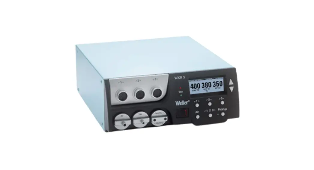
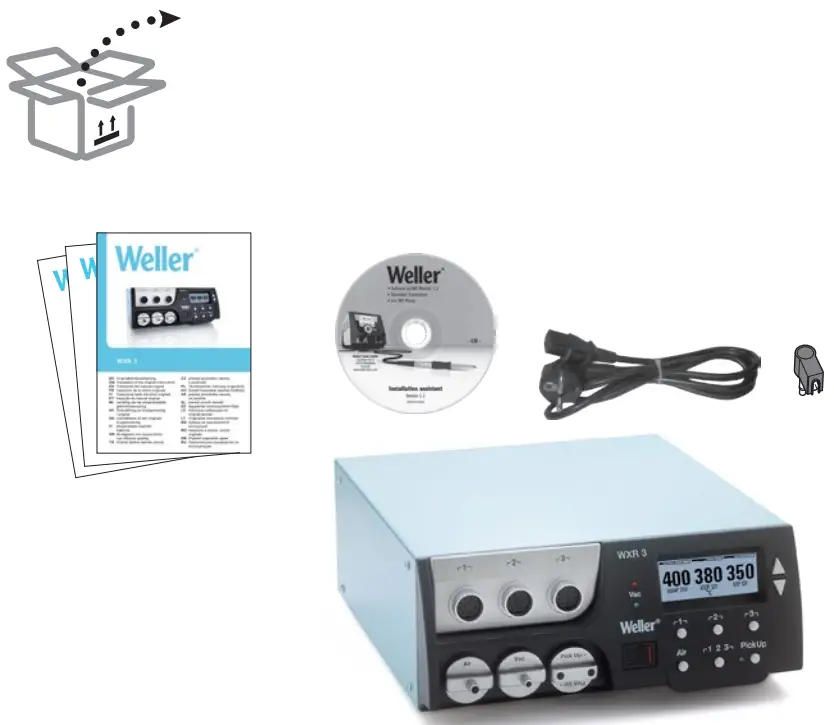
WXR 3 3 Channel Power Unit
Instruction Manual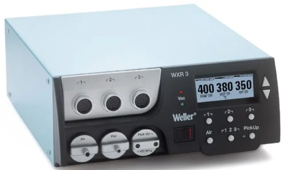
WXR 3
Translation of the original instructions
WXR 3 3 Channel Power Unit


Quick Reference WXR 3
Open Menu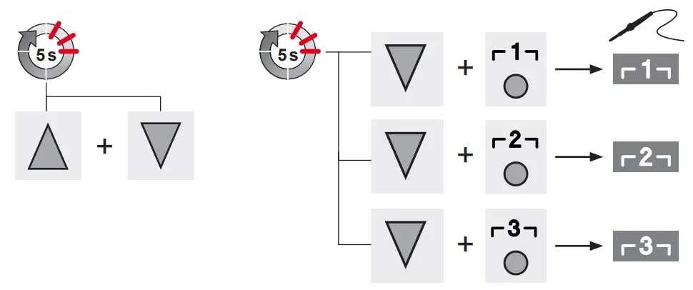
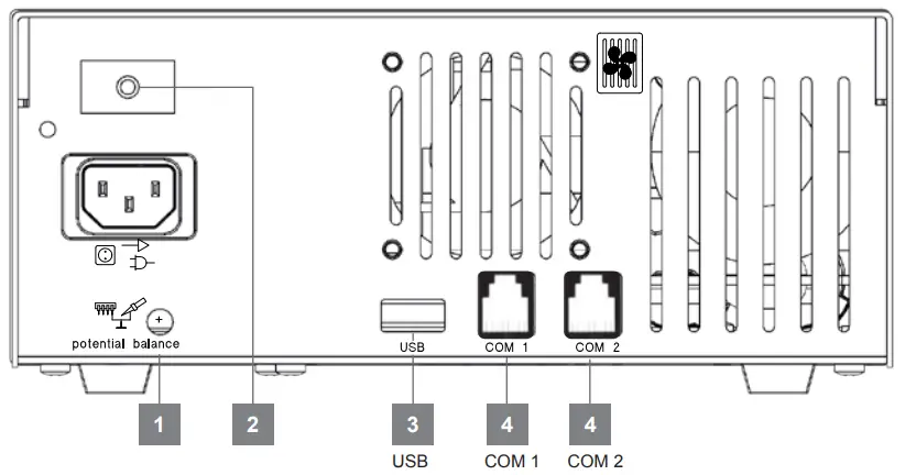
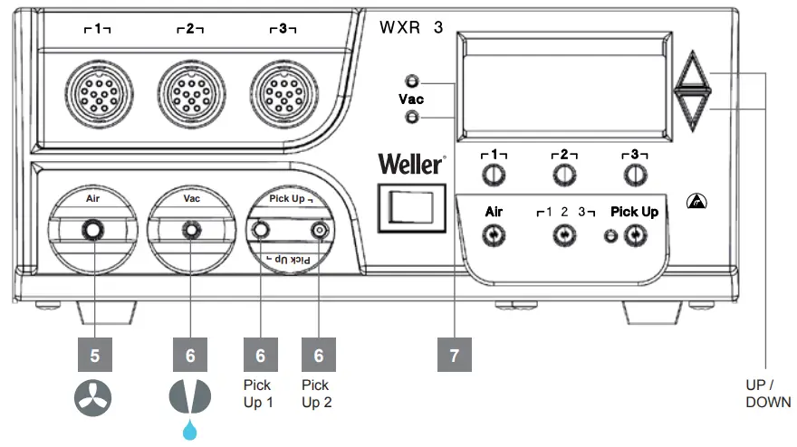
- Equipotential bonding
- Mains fuse
- USB port
- Interface

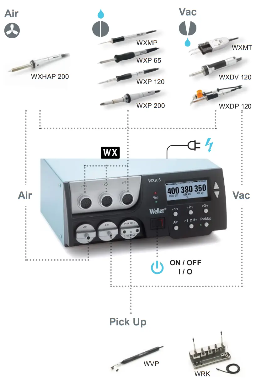
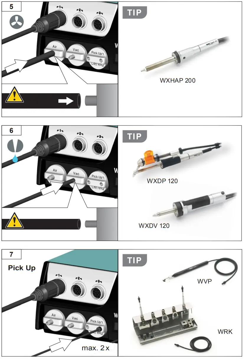
- Air connection nipple for hot air tools
- Vacuum connection
- Vacuum LED
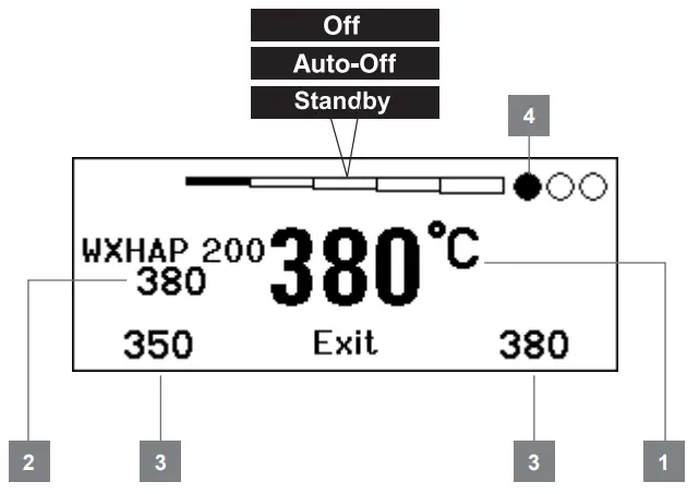
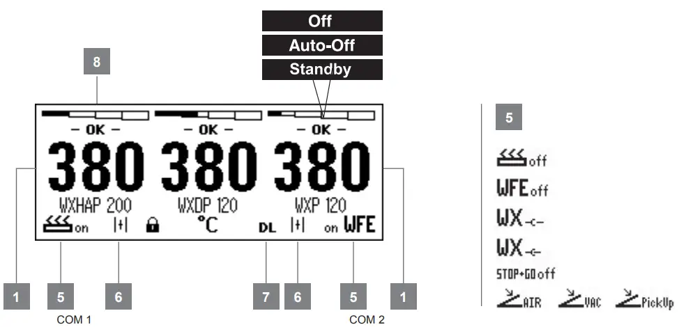
- Actual temperature / nominal temperature
- Nominal temperature
- Fixed temperature
- Active channel

- Interface COM 1 / COM 2
- WFV 60A
Status indication - DATA LOGGER (DL) active
- 2 CH 1, 2, 3 Switching output indicator Starting up the device
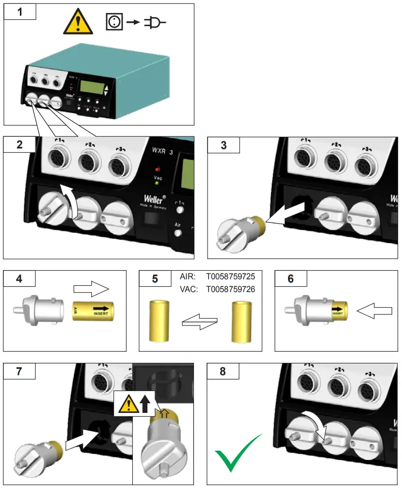
Filter change
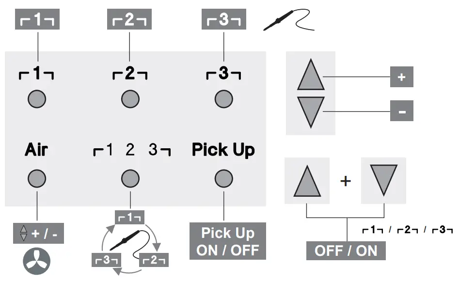
Select channel
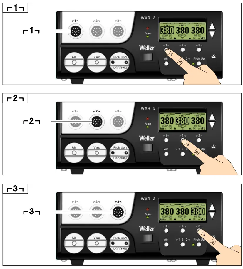 Change channel
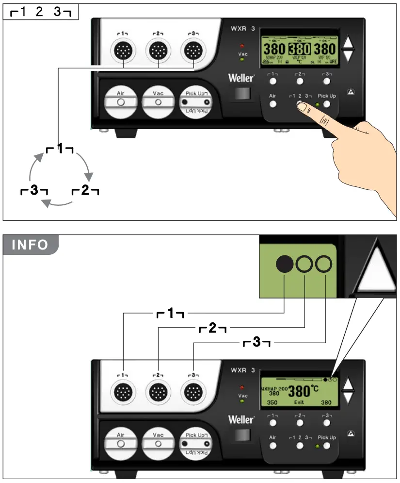
Hot air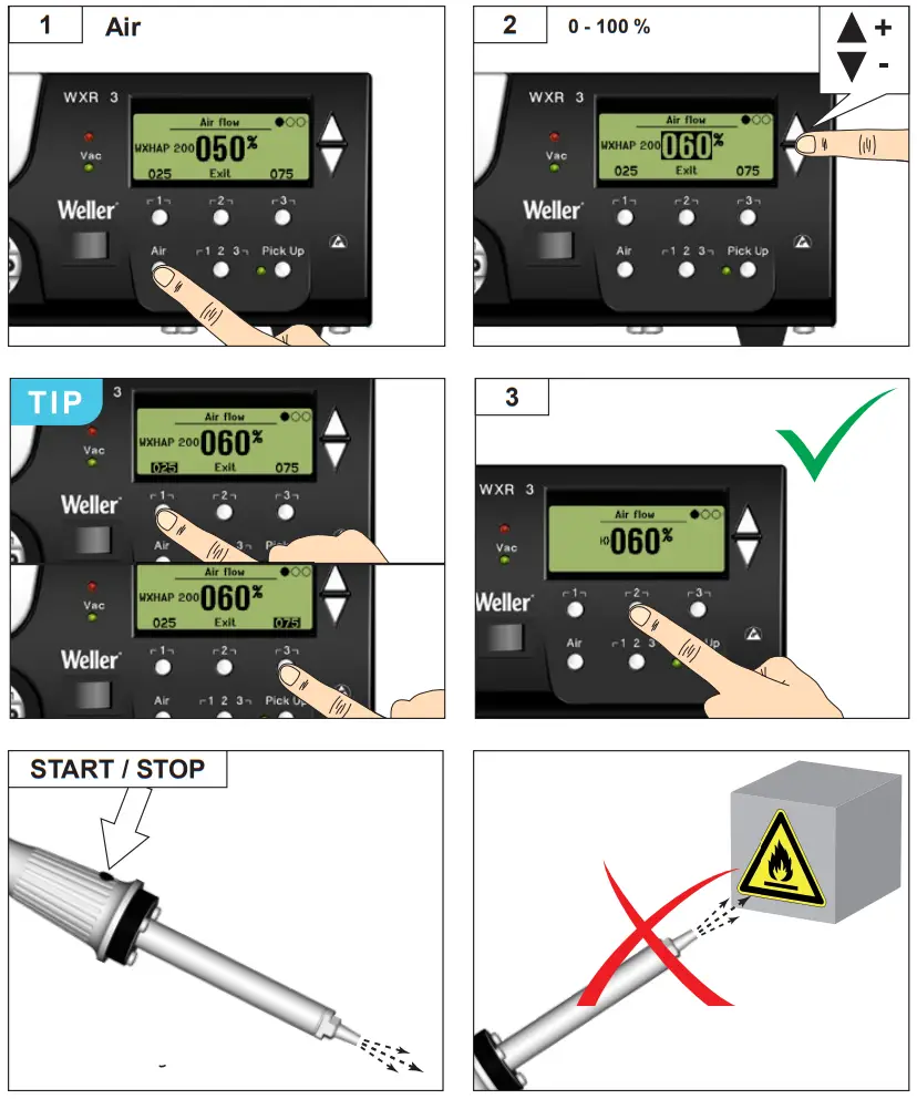
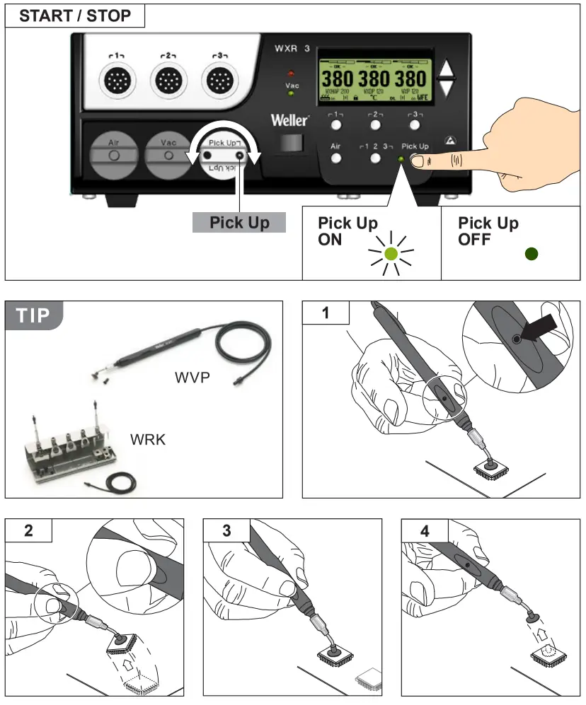
Pick Up vacuum
Switching the channel on/ off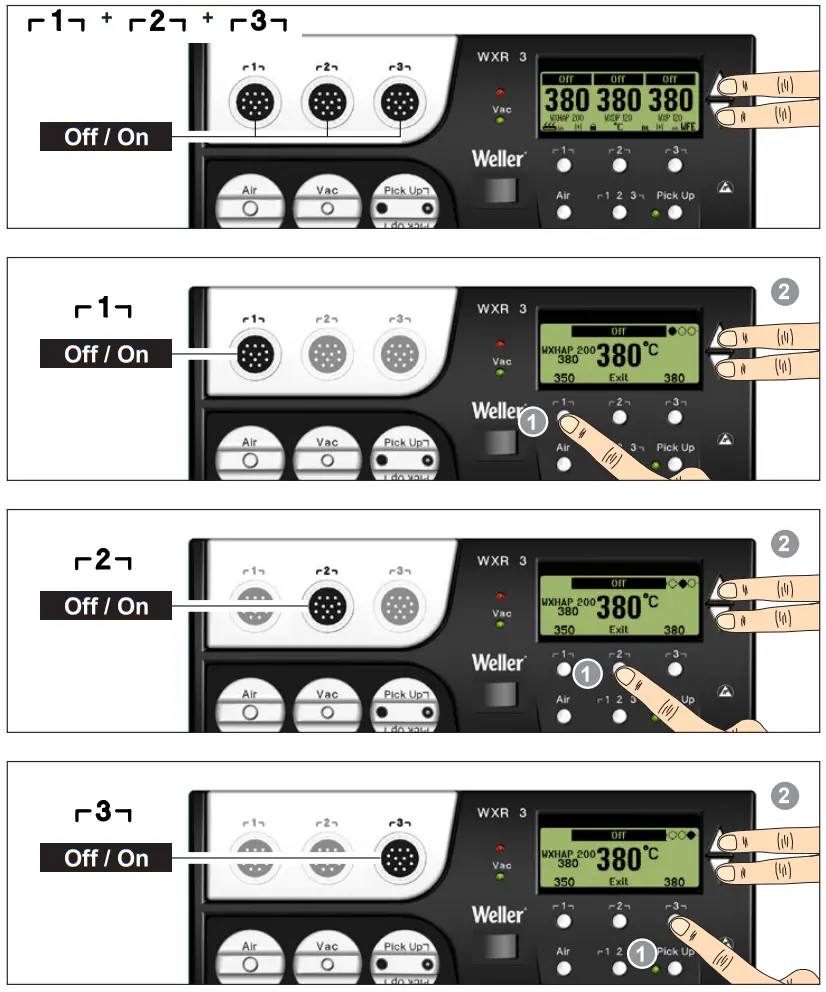
Nominal temperature
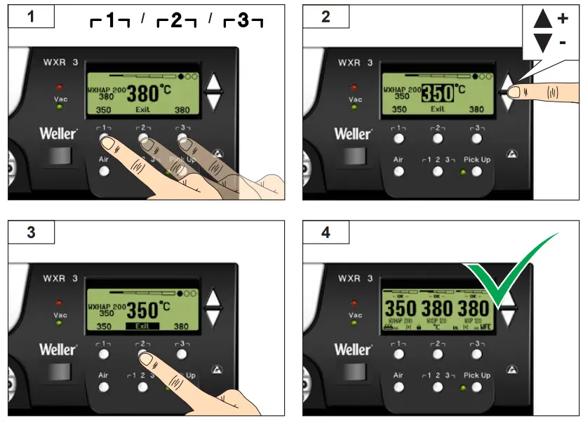
Select ixed temperature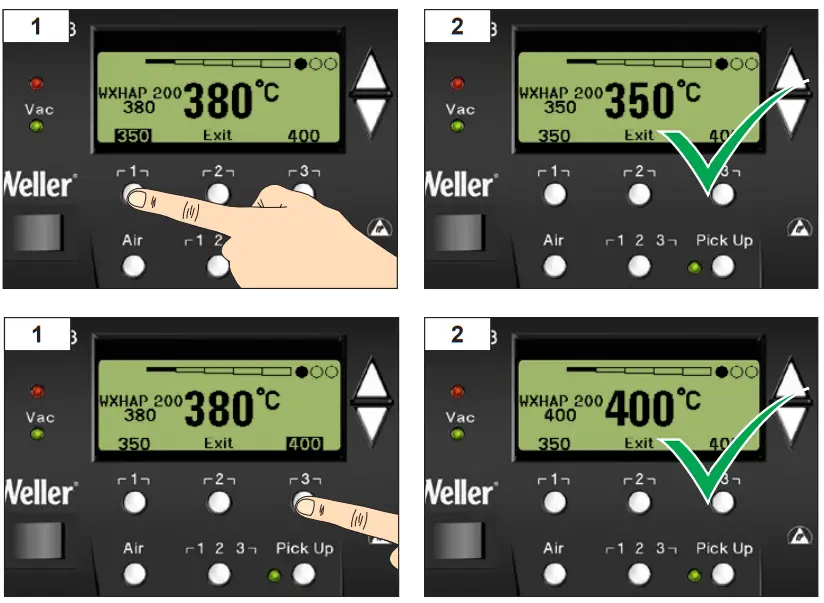
Set and save fixed temperature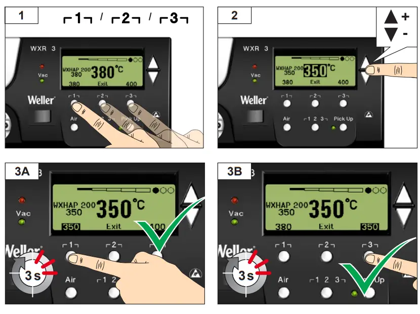 Open Parameter menu
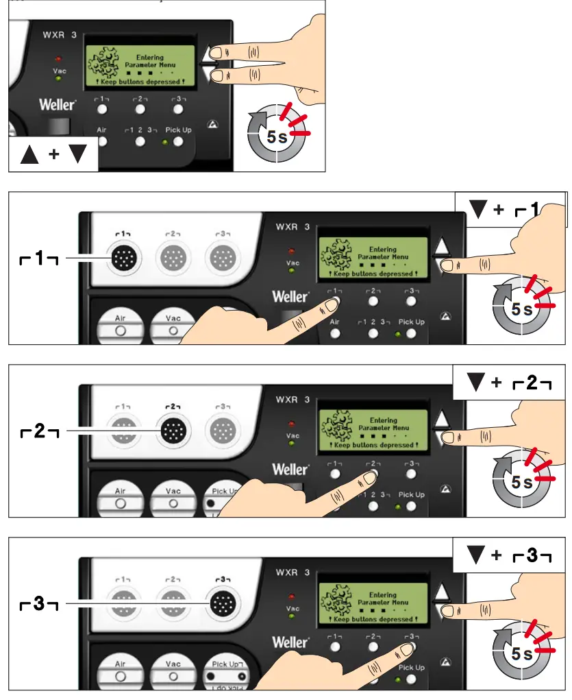 Select/set value
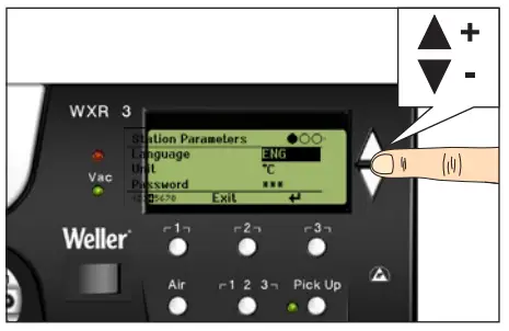
Exit parameter menu
For your safety
Thank you for the confidence you have shown in buying this device.
The device has been manufactured in accordance with the most rigorous quality standards which ensure that it operates perfectly.![]() Read these instructions and the accompanying safety information carefully before starting up the device and starting work with the device.
Read these instructions and the accompanying safety information carefully before starting up the device and starting work with the device.
Keep these instructions in a place that is accessible to all users.
These instructions contain important information which will help you to start up, operate and service the device safely and correctly as well as to eliminate simple faults and malfunctions yourselves.
The device has been manufactured in accordance with state-of-the-art technology and acknowledged regulations concerning safety.
There is nevertheless the risk of personal injury and damage to property if you fail to observe the safety information set out in the accompanying booklet and the warnings given in these instructions.
Safety information
For safety reasons, children and youths under the age of 16, as well as persons who are not familiar with these operating instructions, may not use the device. Children should be supervised in order to ensure that they do not play with the tool.
This device is not intended for use by persons (including children) with limited physical, sensory or mental aptitude, or by persons who lack knowledge or experience in handling the device.
![]() Warning! Electrical shock
Warning! Electrical shock
Connecting the control unit incorrectly poses a risk of injury due to electric shock and can damage the device.
- Carefully read the attached safety information, the safety information accompanying these operating instructions as well as the operating instructions for your control unit before putting the control unit into operation and observe the safety precautions specified therein.
- Only connect WELLER WX tools.
- Never use the USB port as a power supply for third-party devices.
If the device is faulty, active electrical conductors may be bare or the PE conductor may not be functional.
- Repairs must always be referred to a Weller-trained specialist.
- If the electrical tool‘s power supply cord is damaged, this must be replaced with a specially prefabricated power supply cord available through the customer service organization.
Warning! Risk of burns![]() Risk of burns from the soldering tool while the control unit is operating. Tools may still be hot long after they have been switched off.
Risk of burns from the soldering tool while the control unit is operating. Tools may still be hot long after they have been switched off.
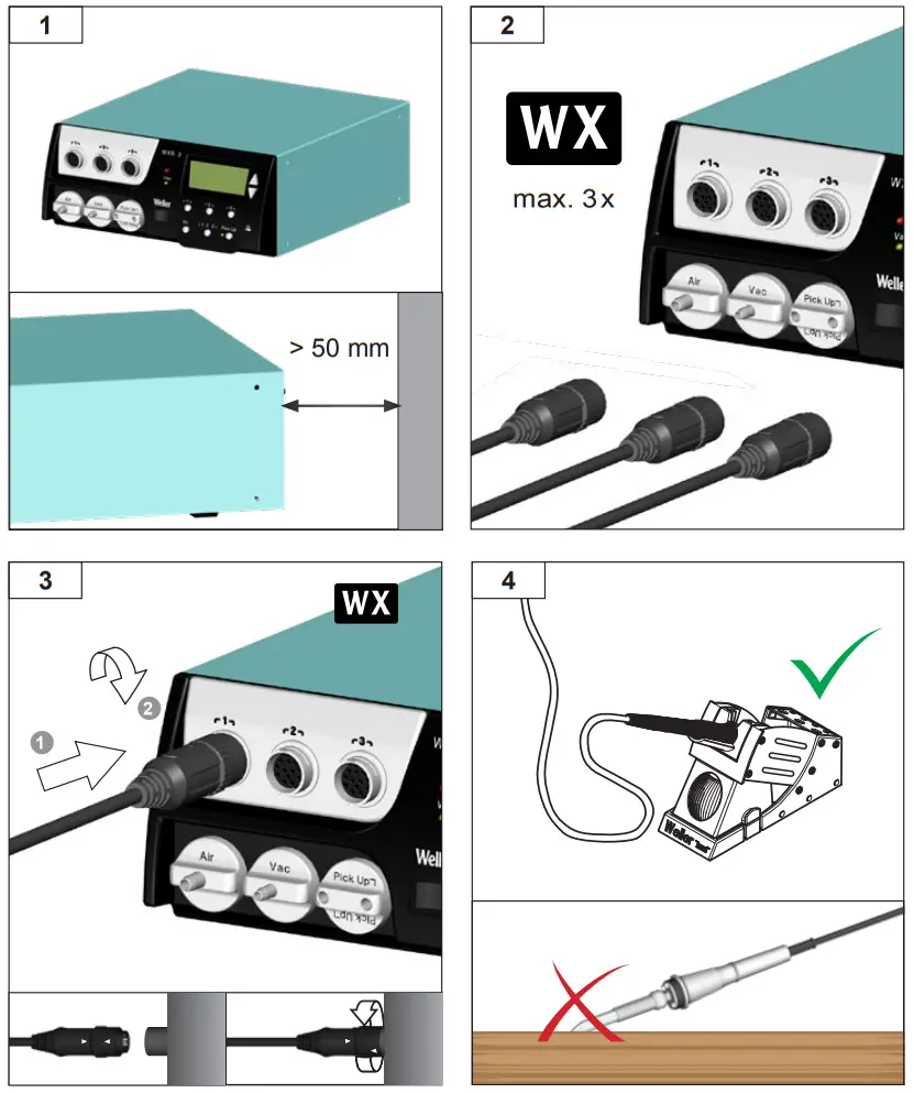
- Always place the soldering tool in the safety rest while not in use.
- Only connect the vacuum and hot air at the designated points.
- Do not direct hot air soldering tools at people or inflammable objects.
Warning! Fire and explosion hazard!![]() Hot tools represent a fire hazard
Hot tools represent a fire hazard
- Always place the soldering tool in the safety rest while not in use.
- Do not direct hot air soldering tools at people or inflammable objects.
- Keep explosive and flammable objects well away from the device.
- Do not cover the device.
Specified Conditions Of Use
Supply unit for WELLER WX soldering tools.
Use the repair station only for the purpose indicated in the operating instructions of soldering and disordering under the conditions specified herein.
![]() Flammable gases and liquids may not be extracted.
Flammable gases and liquids may not be extracted.
The device may only be used with correctly fitted and suitable filter cartridges.
Replace filter cartridges when full.
Only use the device indoors. Protect against moisture and direct sunlight.
Intended use of the soldering station/ disordering station also includes the requirement that you
- adhere to these instructions,
- observe all other accompanying documents,
- comply with national accident prevention guidelines applicable at the place of use.
The manufacturer will not be liable for unauthorized modifications to the device.
User groups
Due to differing degrees of risk and potential hazards, several work steps may only be performed by trained experts.
| Work step | User groups |
| Default soldering parameters | Specialist personnel with technical training |
| Replacing electrical replacement parts | Electricians |
| Default maintenance intervals | Safety |
| Operation Filter change | Non-specialists |
| Operation Filter change Replacing electrical replacement parts | Technical trainees under the guidance and supervision of a trained expert |
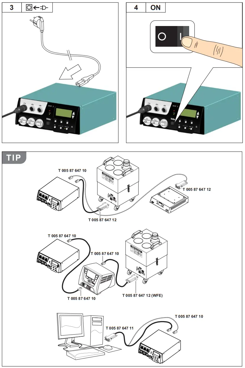
Starting up the device
Caution!
Please adhere to the operating instructions of the connected devices.
Put the tool into operation as described in the chapter „Placing into operation“.
![]() Check to see if the mains voltage matches the ratings on the nameplate.
Check to see if the mains voltage matches the ratings on the nameplate.
Make sure the machine is switched off before plugging in.
After switching on the device, the microprocessor carries out a self- test and reads out the values of the parameters stored in the tool.
The set-point temperature and fixed temperatures are stored in the tool. The actual temperature value increases to the set-point temperature (= soldering tool is heated up).
Soldering and disordering
Carry out soldering work as directed in the operating instructions of your connected soldering tool.
Handling the soldering tips
- Coat the selective and tenable soldering tip with solder when heating it up for the first time. This removes oxide coatings which have formed during storage and impurities from the soldering tip.
- Make sure that the soldering tip is well coated with solder during breaks between soldering work and prior to storage of the device.
- Do not use aggressive fluxing agents.
- Always make sure that the soldering tips are fitted properly.
- Select as low a working temperature as possible.
- Select the largest possible soldering tip shape for the application. Rule of thumb: the soldering tip should be roughly as large as the soldering pad.
- Coat the soldering tip well with solder to ensure that there is efficient heat transfer between the soldering tip and the soldering area.
- Prior to extended breaks between soldering work, switch off the soldering system or use the Weller function to reduce the temperature when the soldering equipment is not in use.
- Coat the tip with solder prior to storage if you do not intend to use the soldering iron for an extended period of time.
- Apply solder directly to the soldering area, not to the soldering tip.
- Change the soldering tips using the designated tool.
- Do not apply mechanical force to the soldering tip.
Notice
The control units have been adapted to hold a medium-sized soldering tip. Discrepancies may occur if the tip is changed or a different shaped tip is used.
Overload cut-out
To avoid overloading the station, power output is automatically reduced in the event of an overload.
Equipotential bonding
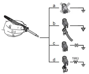
Four variants are possible by connecting the 3.5 mm jack socket differently:
| a | Hard-grounded | supplied without plug. |
| b | Equipotential bonding | with plug, equalizer at center contact. |
| c | Floating | with plug |
| d | Soft-grounded | with plug and soldered resistor. Grounded through selected resistor. |
Carrying out a firmware update
Notice
The station must not be switched off while the firmware update is running.
Switch off station 1.
2. Insert the memory stick into the USB port.
Switch on station 3.
The firmware update is performed automatically.
If you have a more already installed more recent firmware on your station, this will not be changed.
Care and maintenance
| Warning! Before doing any work on the machine, pull the plug out of the socket. | |
 | Warning! Use original replacement parts only. |
| Warning! Risk of burns „ Only replace solder tips when cold „ Replace and clean suction nozzles only when hot and using the suitable tool „ Only replace hot air nozzles using the suitable tool „ Only clean or replace solder collection tubes when cold |
Clean the operator panel, if dirty, using a suitable cleaning cloth.
Filter change
Check the filter regularly for contamination, and replace it if necessary.
Warning!
Failure to use a filter will cause irreparable damage to the vacuum pump.
„ Check before starting soldering whether a main filter is inserted.
Contaminated filters must be treated as special waste.
Dispose of replaced equipment parts, filters or old devices in accordance with the rules and regulations applicable in your country. Wear suitable protective gear.
Parameter menu
Standby Temp. ![]() Menu access ▶ Tool parameters
Menu access ▶ Tool parameters
The soldering tools have a usage detection device (sensor) in the handle which automatically initiates cooling to Standby temperature when the soldering tool is not in use.
Standby time (temperature deactivation)
When the soldering tool is not in use, the temperature is reduced to Standby temperature on expiration of the set Standby time. The display reads „Standby“.
Press control key to exit Standby mode. The sensor integrated tool detects the change in state and deactivates Standby mode as soon as the tool is moved.
| Option | Description |
| OFF | standby time is deactivated (factory setting) |
| 1-999 min | standby time, individually adjustable |
| — | The tool is not supported |
AUTO OFF time (automatic switch-off time)
When the soldering tool is not in use, the soldering tool heater is switched off when the AUTO OFF time expires.
Temperature deactivation is performed independently of the set standby function. The actual temperature is indicated and serves as a residual heat display. The display reads „AUTO OFF“.
| Option | Description |
| OFF | AUTO OFF function is deactivated (factory setting) |
| 1-999 min | AUTO-OFF time, can be set individually. |
Sensitivity
| Option | Description |
| low | Non-sensitive – Reacts to heavy (long) movement |
| normal | standard (factory setting) |
| high | Sensitive – Reacts to light (short) movement |
| — | The tool is not supported |
Max. hot air duration WXHAP
The on-time of the hot air flow of the WXHAP can be limited in increments of 1 to between 0 and 300 sec. The factory default is 0 s („OFF“), i.e. air flows only as long as the button on the hot air tool or the optional footswitch is pressed.
| Option | Description |
| OFF | No duration defined (factory setting) |
| 1-300 s | Individually |
Offset (Temperature-Offset)
The actual soldering-tip temperature can be adapted by entering a temperature offset around ± 40 °C (± 72 °F).
Perform. Mode
The function determines the heating characteristics of the soldering tool to achieve the set tool temperature.
| Option | Description |
| standard | adapted (medium) heating (factory setting) |
| min. | slow heating |
| max. | rapid heating |
Button lock WXHAP
This function can be used to adjust the factory button presets of the WXAHP tool.
| Option | Description |
| OFF | – |
| ON | The WXHAP is switched on the first time the button is pressed and switched off the next time the button is pressed. |
Process window
The temperature range set in the process window determines the signal response of the floating switching output.
Notice
On tools with an LED ring light (e.g. WXDP 120), the process window defines the illumination characteristics of the LED ring light.
If the LED is continuously illuminated, this means that the preselected temperature has been reached or that the temperature is within the predetermined process window.
A flashing LED indicates that the system is heated or that the temperature is outside the process window.
Language
| CHN | 中文 |
| DEN | Dansk |
| ENG | English |
| ESP | Español |
| FIN | Suomi |
| FRA | Français |
| GER | Deutsch |
| HUN | Magyar |
| ITA | Italiano |
| POR | Português |
| RUS | Pусский |
| SWE | Svenska |
| TUR | Türkçe |
| JPN | 日本語 |
| POL | Polski |
| KOR | 한국말 |
| CZE | Český |
Temperature version °C/°F (temperature units)
| Option | Description |
| ° C | Celsius |
| ° F | Fahrenheit |
Password (lock function)
After switching the lock function on, only the fixed temperature keys can be operated on the soldering station.
All other settings are disabled until the repair station is unlocked again.
Notice
If you want only one temperature value to be selectable, the control keys fixed temperature keys) must be set to the same temperature value.
Locking the soldering station
Set the desired three-digit locking code (between 001 and 999) using the UP / DOWN buttons. Confirm the code with the Enter key. The lock is active (the display shows a lock symbol).
- Call up the parameter menu. If the lock function is active, the password menu item opens automatically. Threestars (***)areshownon the display.
- Set the three-digit locking code using the UP /DOWN buttons.
- Confirm the code with the Enter key.
Single-channel display
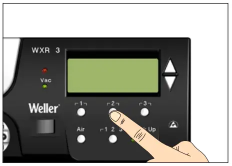
To obtain more straightforward readings, the display mode from can switched from 3-channel display to 1-channel display.
If single-channel display is selected, the device does not reset automatically to 3-channel display after setting the temperature of a tool channel. The display mode can be reset using ┌ 2 ┐.
| Option | Description |
| OFF | Automatic reset to 3-channel display (factory setting) |
| ON | No automatic reset to 3-channel display |
Vacuum pre-feed
In order to prevent the pump from starting prematurely or to ensure a defined soldering-joint preheating time, it is possible to set an ON delay.
| Option 0 sec | Description |
| 0 sec | OFF: vacuum pre-feed function is OFF (factory setting) |
| 1-10 sec | ON: vacuum pre-feed time, individually |
Vacuum run-on
| Option | Description |
| 0 sec | OFF: vacuum run-on function is OFF (factory setting) |
| 1-10 sec | ON: vacuum run-on time, individually adjustable |
Pressure gauge threshold
This function can be used to define the maintenance interval of the disordering tool. This is done by setting the value in mbar at which the electric pressure gauge issues a warning signal when the intake system is contaminated (LED of the vacuum pump switches from green to red). The set value is dependent on the suction nozzles used.
Adjustable -400 mbar to -800 mbar factory setting -600 mbar
- The system (tips and filter) must be free.
- Select the menu item „Pressure gauge threshold“ in the menu.
- Set the „Pressure gauge threshold“ pressure value with the UP or DOWN button. The status LED switches back and forth between red and green. Use the UP button to increase vacuum by 50 to 80 mbar, then pinch the vacuum tube and check whether the LED switches from green to red.
- Adopting the set change.
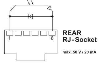
Interface COM 1 / 2
| Option | Description |
| RS232 | Serial communication with PC or other compatible Weller devices (factory setting). |
| Air | The COM 1 port is configured as a foot switch input for activating the air flow. |
| Vic | The COM 1 port is configured as a foot switch input for activating the vacuum. |
| Pickup | The COM 1 port is configured as a foot switch input for activating the PickUp vacuum. |
| Stop Go | The COM 1 port is used to drive an optional opt transmitter so that a KHE–P control unit can be activated via an optical fibre. The output is activated when a tool is used. In addition, the floating switched output is closed. The output is off in the Standby, Auto Off or Off positions, or if no tool is inserted. |
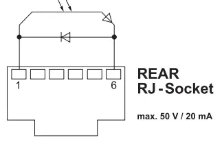
Floating switching output 1
Floating switching output 1 is located at the COM 1 port.
| Option | Description |
| OFF | (factory |
| Zero Smog | The floating switching output is closed when a tool is in use. Selected Zero Smog extraction systems can be connected using an optional adaptor (WX HUB). The rear RS 232 port remains functional. Switching output is open in the Standby, Auto Off or Off positions, or if no tool is inserted. |
Notice
If the COM 1 port is also configured for „Stop Go“ use, the „Filter full“ message is evaluated by the WX HUB and, where applicable, a message appears on the display .
Floating switching output 2
Floating switching output 2 is located at the COM 2 port.
| Option | Description |
| OFF | (factory setting) |
| CH 1 | Tool channel 1 controls the switching output |
| CH 1+2 | Tool channel 1 + 2 controls the switching output |
| CH 1+2+3 | Tool channel 1 + 2 + 3 controls the switching output |
Notice
If the robot is at working temperature, the display will show – ok –.
Technical Data
| Repair station | WXR 3 |
| Dimensions LxWxH | 273 x 235 x 102 mm (10,75 x 9,25 x 4,02 inch) |
| Weight | ca. 6,7 kg |
| Mains supply voltage | 230 V, 50 Hz 10053500699 120 V, 60 Hz WXR 3 100 V 50/60 Hz 10053500199 |
| Power consumption | 420 W (600 W) |
| Safety class | I, antistatic housing III, Soldering tool |
| Fuse | Overcurrent release 230 V; 2,0 A 120 V; 4,0 A |
| Temperature range | Celsius: 100 – 450°C (550°C) Fahrenheit: 200 – 850°F (999°F) Controllable temperature range is tool-dependent |
| Temperature accuracy | ± 9 °C (± 17 °F) Tool dependent (WXHAP 200 ±30 °C / ±80 °F) |
| Temperature stability | ± 2 °C (± 4 °F) |
| Equipotential bonding | Via 3.5 mm pawl socket on back of unit |
| Display | 240 x 88 dots / Backlighting |
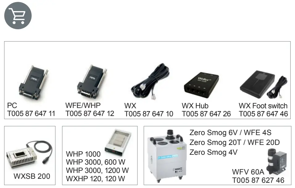
| USB port | The control unit comes with a USB port for installing firmware updates, configuration and monitoring. |
| Pump (Intermittent mode (30/30) s) | Max. vacuum 0,7 bar Max. delivery rate 18 Cumin Max. hot air 15 l/min |
| Additional vacuum pump | Max. vacuum0,5 bar Max. delivery rate 1,7 Cumin |
Error messages and error clearance
| Message/symptom | Possible cause | Remedial measures |
| Display: „- – – | „ Tool has not been detected „ Tool defective | „ Check connection of tool to device „Check connected tool |
| No display function (display OFF) | „ No mains supply voltage | „ Turn on mains power switch „ Check mains supply voltage „ Check device fuse |
| No vacuum at disordering tool | „ Vacuum not connected „ DE soldering nozzle clogged „ Pump faulty | „ Connect vacuum hose to vacuum connection „ Service disordering nozzle using cleaning tool |
| Insufficient vacuum at disordering tool | „ Filter cartridge on disordering tool full „ Main filter full | „ Change filter cartridge on disordering tool full „ Change the main filter element on the soldering station |
| Hot air tool has no air | „ Air hose not connected „ Main filter full | „ Connect or check air hose „ Change main filter cartridge on soldering station |
Symbols
| Caution! | |
| Read the operating instructions! | |
 | Before performing work of any kind on the unit, always disconnect the power plug from the socket. |
 | ESD-compatible design and ES Compatible workstation |
 | Equipotential bonding |
 | Fuse |
 | Safety |
| CE | |
| British | |
| Soldering | |
 | DE soldering |
 | Hot air |
Disposal![]() Do not dispose of electric tools together with household waste material! In observance of European Directive 2012/19/ EU on waste electrical and electronic equipment and its implementation in accordance with national law, electric tools that have reached the end of their life must be collected separately and returned to an environmentally compatible recycling facility. Dispose of replaced equipment parts, filters or old devices in accordance with the rules and regulations applicable in your country.
Do not dispose of electric tools together with household waste material! In observance of European Directive 2012/19/ EU on waste electrical and electronic equipment and its implementation in accordance with national law, electric tools that have reached the end of their life must be collected separately and returned to an environmentally compatible recycling facility. Dispose of replaced equipment parts, filters or old devices in accordance with the rules and regulations applicable in your country.
Disposal – UK![]() Do not dispose of electric tools together with household waste material! In observance of British Directive 2013 No. 3113 on waste electrical and electronic equipment and its implementation in accordance with national law, electric tools that have reached the end of their life must be collected separately and returned to an environmentally compatible recycling facility.
Do not dispose of electric tools together with household waste material! In observance of British Directive 2013 No. 3113 on waste electrical and electronic equipment and its implementation in accordance with national law, electric tools that have reached the end of their life must be collected separately and returned to an environmentally compatible recycling facility.
Warranty
Claims by the buyer for physical defects are time-barred after a period of one year from delivery to the buyer. This does not apply to claims by the buyer for indemnification in accordance with §§ 478, 479 BGB (German Federal Law Gazette).
We shall only be liable for claims arising from a warranty furnished by us if the quality or durability warranty has been furnished by use in writing and using the term „Warranty“.
The warranty shall be void if damage is due to improper use and if the device has been tampered with by unauthorized persons.
Subject to technical alterations and amendments.
For more information please visit www.weller-tools.com.
WXR 3
EC declaration of conformity
We hereby declare that the products described herein comply with the following guidelines:
UK declaration of conformity
We hereby declare that the products described herein comply with the following guidelines:
2004/108/EG, 2011/65/EU (RoHS), 2006/42/EG![]() Besigheim, 2022-12-12
Besigheim, 2022-12-12

Philippe Building
Managing director
Authorized to compile technical documentation.
2008 No.1597, SI 2012 No.3032, SI 2016 No.1091
Besigheim, 2022-12-12

Philippe Building
Managing director
Weller Tools GmbH
Carl-Benz-Straße 2, 74354 Besigheim, Germany
Authorised to compile technical documentation.
Apex tool Group (UK Operations) Limited
Piccadilly, Tamworth
Staffordshire B78 2ER
Product Registration
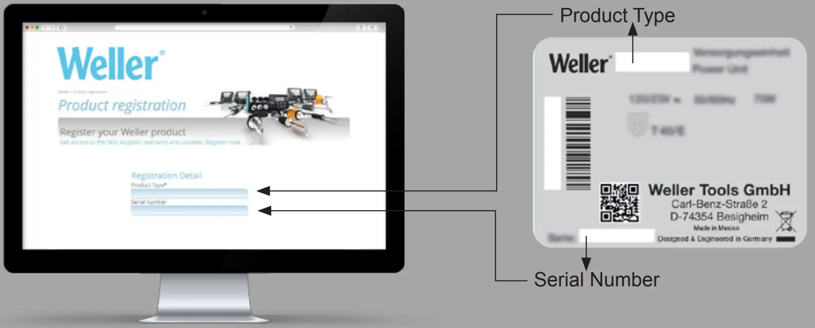
www.weller-tools.com/registration

http://www.weller-tools.com/registration
| GERMANY Weller Tools GmbH Carl-Benz-Straße 2 74354 Besigheim Tel: +49 (0)7143 580-0 Fax: +49 (0)7143 580-108 | USA Apex Tool Group, LLC. Weller Professional Tools Division1000 Lufkin Road Apex, NC 27539 +1 919-362-8381 [email protected] | CHINA Apex Tool Group Room 302A, NO 177 Bubo Road Shanghai, 201202 Tel: +86 (21) 60880288 Fax: +86 (21) 60880289 | GREAT BRITAIN Apex tool Group (UK Operations) Limited Piccadilly, Tamworth Staffordshire B78 2ER |
![]()
www.weller-tools.com
© 2022, Apex Tool Group, LLC.
Weller® is a registered Trademark and registered Design of Apex Tool Group, LLC.


