Munic C4D-4MUSAB V8 OBD Dongle Installation Guide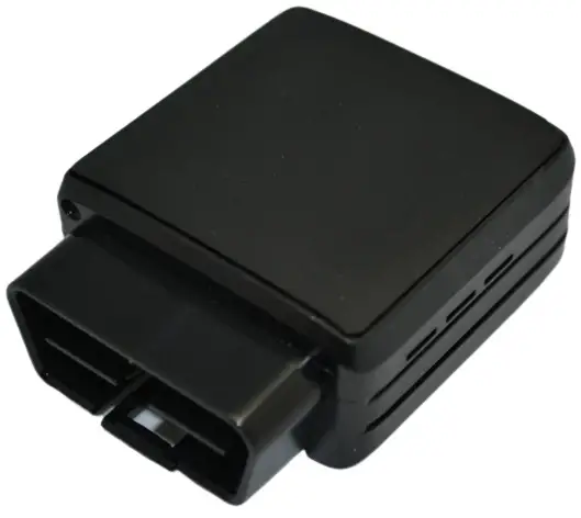
Preface
The information contained in this installation guide is subject to changes in order to improve the reliability, design or features without prior notice. MUNIC Car Data reserves the right to make changes in the content without obligation to notify any person or organisation of such changes or improvements. MUNIC Car Data can in no event be held liable for technical or editorial errors or omissions herein, nor for incidental, special or consequential damages from the furnishing, performance or use of this installation guide.
Please contact our technical support for current updates and supplemental information concerning the use and operation of this or other MUNIC Car Data products.
Warnings and notices
![]() The exclamation point within an equilateral triangle is intended to alert the user
The exclamation point within an equilateral triangle is intended to alert the user
to the presence of important operating and maintenance (servicing) instructions in the literature accompanying the product.
Please read the installation guidelines, as well as the safety and operating instructions before operating your device. Follow all instructions and heed all warnings in the installation guide.
There is a risk of explosion if the battery is replaced by a wrong battery type. Please discard empty battery according to local regulations.
Dispose of used batteries according to the instructions.
FCC Regulations
This device complies with part 15 of the FCC Rules. Operation is subject to the following two conditions:
- This device may not cause harmful interference, and
- this device must accept any interference received, including interference that may cause undesired operation.
This device has been tested and found to comply with the limits for a Class B digital device, pursuant to Part 15 of the FCC Rules. These limits are designed to provide reasonable protection against harmful interference in a residential installation. This equipment generates, uses and can radiated radio frequency energy and, if not installed and used in accordance with the instructions, may cause harmful interference to radio communications. However, there is no guarantee that interference will not occur in a particular installation If this equipment does cause harmful interference to radio or television reception, which can be determined by turning the equipment off and on, the user is encouraged to try to correct the interference by one or more of the following measures:
- Reorient or relocate the receiving antenna.
- Increase the separation between the equipment and receiver.
- Connect the equipment into an outlet on a circuit different from that to which the receiver is connected.
- Consult the dealer or an experienced radio/TV technician for help.
Caution: Changes or modifications not expressly approved by the party responsible for compliance could void the user‘s authority to operate the equipment.
FCC RF Exposure Information (SAR)
This device is designed and manufactured not to exceed the emission limits for exposure to radio frequency (RF) energy set by the Federal Communications Commission of the United States.
During SAR testing, this device is set to transmit at its highest certified power level in all tested frequency bands and placed in positions that simulate RF exposure in usage near the body with the separation of 15 mm. Although the SAR is determined at the highest certified power level, the actual SAR level of the while operating can be well below the maximum value. This is because the device is designed to operate at multiple power levels to use only the power required to reach the network. In general, the closer you are to a wireless base station antenna, the lower the power output.
The exposure standard for wireless employs a unit of measurement known as the Specific Absorption Rate, or SAR. The SAR limit set by the FCC is 1.6 W/kg.
The FCC has granted an Equipment Authorization for this model device with all reported SAR levels evaluated as in compliance with the FCC RF exposure guidelines. SAR information on this model device is on file with the FCC and can be found under the Display Grant section of www.fcc.gov/oet/ea/fccid after searching on FCC ID: A6GC4D-4MUSABV8.
For this device, the highest reported SAR value for usage near the body is 0.94 W/kg.
While there may be differences between the SAR levels of various devices and at various positions, they all meet the government requirement.
SAR compliance for body operation is based on a separation distance of 15mm between the unit and the human body.
Hardware features
| OBD Dongle | ||
| Performance | Processor | ARM A7 |
| RAM | 2 Gbytes | |
| NAND Flash | 2 Gbytes | |
| Power supply | External power supply range | 8-18V |
| External voltage measurement | ● | |
| Li-pol battery | 450mAh | |
| Communication | Modem | LTE Cat M1 & EGPRS Module (BG96) |
| Bands | LTE: band 2, 4, 12 GSM: band 850 MHz , 1900 MHz | |
| Modem antenna | Internal | |
| SIM | Micro SIM clot | |
| Positioning | GNSS receiver | U-blox M8 (GPS, GLONASS) |
| GNSS antenna | Internal | |
| Interface & Telematics features | IMU | Accelerometer 3 axis ±2/4/8/16 G |
| OBD protocols | CAN, KWP2000, VPW, PWM | |
| CAN interface | Single CAN coprocessor | |
| Leds | 1 bicolor LED | |
| Environmental | Connectors | OBD connector Micro USB type B connector |
| Operating temperature | -20°C/+50°C with Battery | |
| Dimensions | With OBD connector: 27x50x61 mm Without OBD connector: 27x50x49 mm | |
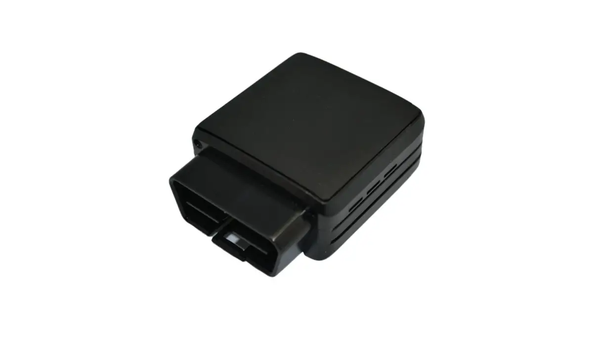
Hardware description
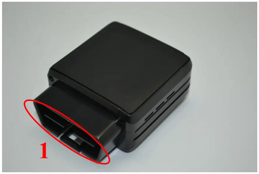
External view
- 1: OBD connector

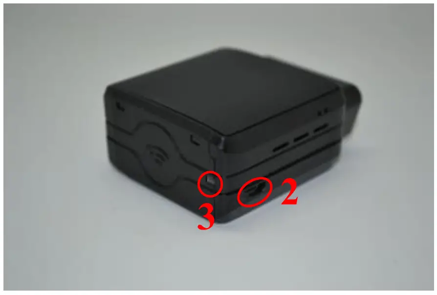
- 2: micro USB connector
- 3: bicolor led

Internal view
- 5: GNSS antenna
- 6: micro SIM holder
- 7: Internal battery*

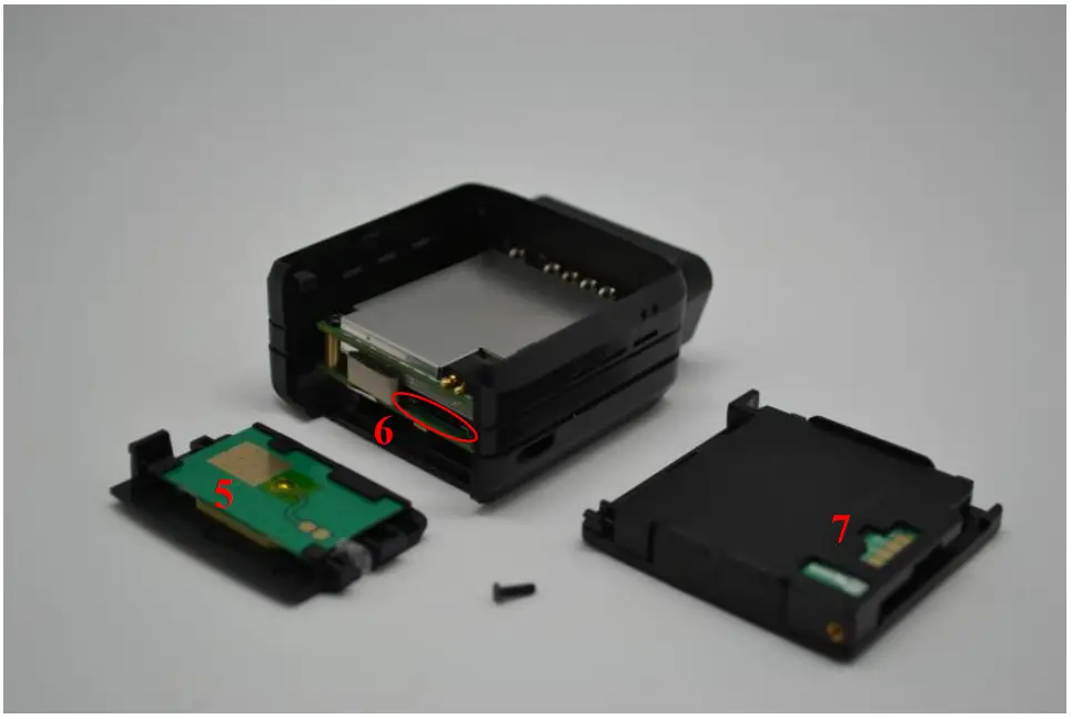
Please read warnings section at the beginning of the installation guide
OBD connector pin out
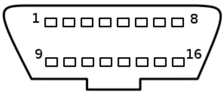
| Pin # | Comment |
| 1 | OEM specific |
| 2 | J1850+ (PWM/VPW) |
| 3 | OEM specific |
| 4 | Chassis ground |
| 5 | Signal ground |
| 6 | CAN High |
| 7 | K line |
| 8 | OEM specific |
| 10 | J1850- (PWM) |
| 11 | OEM specific |
| 14 | CAN low |
| 15 | L line |
| 16 | Battery voltage |
OBD adapter wires
This adapter is only used to connect the OBD to a computer (laptop/desktop).
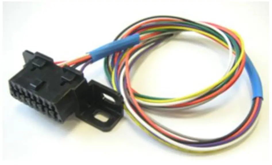
| Pin # | Wire color |
| 2 | Yellow |
| 4 | Black |
| 5 | Grey |
| 6 | Green |
| 7 | Blue |
| 10 | Violet |
| 14 | Orange |
| 15 | White |
| 16 | Red |
Preparing/installing the device
Those operations may need the use of specific tools like :
- Small cross-head screwdriver for the screw.
- Small slotted screwdriver to remove the cover.
- Thin tweezers to insert/remove the SIM card.
Open the device
Remove the screw using Small cross-head screwdriver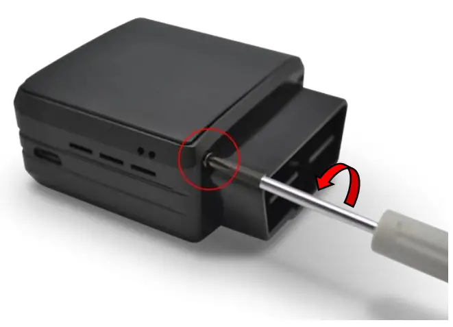
Insert slotted screwdriver to pop-out the top cover and extract it.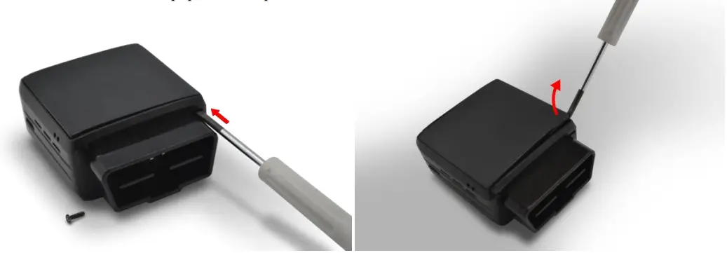
Move apart the side of the device first and then pull the back cover out of his spot.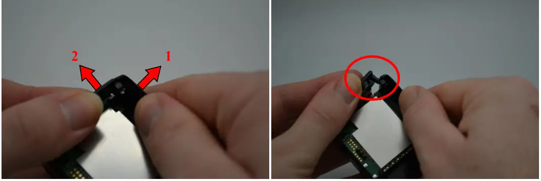
Device is now open
Insert the SIM card
The micro SIM card slot is located between the two electronic cards.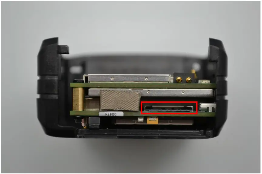
Insert the card with contact on bottom into the slot and push it as far as it will go.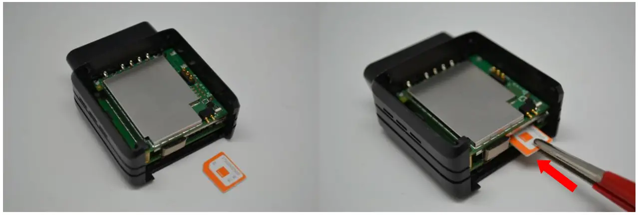
Once inserted the SIM card looks like this: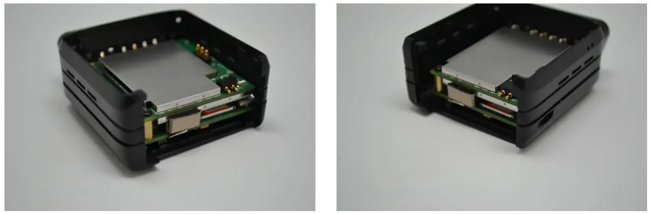
Properly close the device
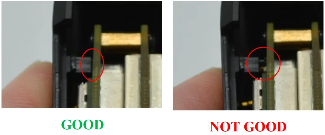
First, check that the hole of the electronic card is correctly inserted in the plastic part.
If it’s not inserted please move smoothly the electronic cards right and left to place it in correct position.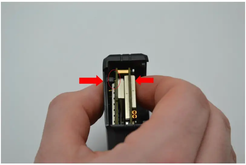
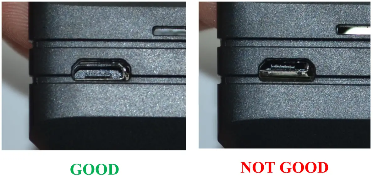
Second, check that the micro USB port is correctly inserted on its place.
If it’s not inserted please move smoothly the electronic cards to place it in correct position.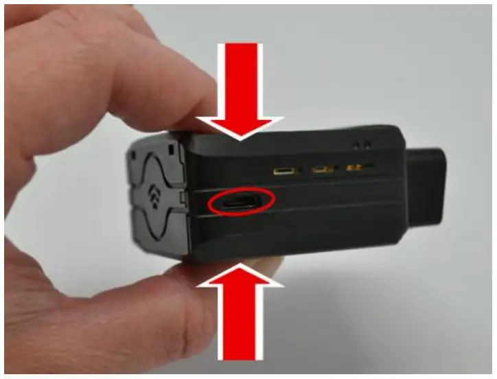
insert the GPS antenna as shown below.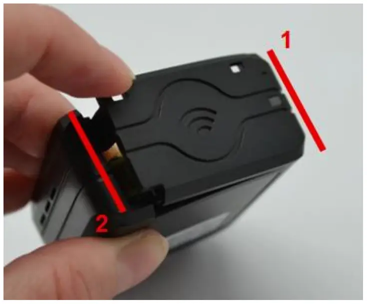
Finally, insert the battery and place the screw.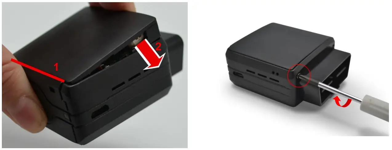
Install the OBD Dongle
Connect the OBD Dongle on your vehicle OBD connector.
LED sequences
The Dongle has a two-coloured LED, green and red.
When both colours are brightened, you can see an orange light.
| Green LED | Red LED | ||
| Sequence | Meaning | Sequence | Meaning |
| Dongle OFF | OFF | ||
| No Modem /No GNSS | 3 times (50ms ON/100ms OFF) 3550ms OFF | Ext. Power/Run | ON |
| No Modem /Fix GNSS | 2 times (50ms ON/100ms OFF) 3700ms OFF | ||
| Modem OK /No GNSS | 1 time (50ms ON/100ms OFF) 3850ms OFF | ||
| Modem OK /Fix GNSS | 2000ms ON 2000ms OFF | ||
| Shutdown/Hibern ate | 30ms ON / 1 s OFF | ||
| Idle/Sleep | 30ms ON / 1 s OFF | ||
Support
For all questions not related in this installation guide, please contact the support team by email at [email protected]