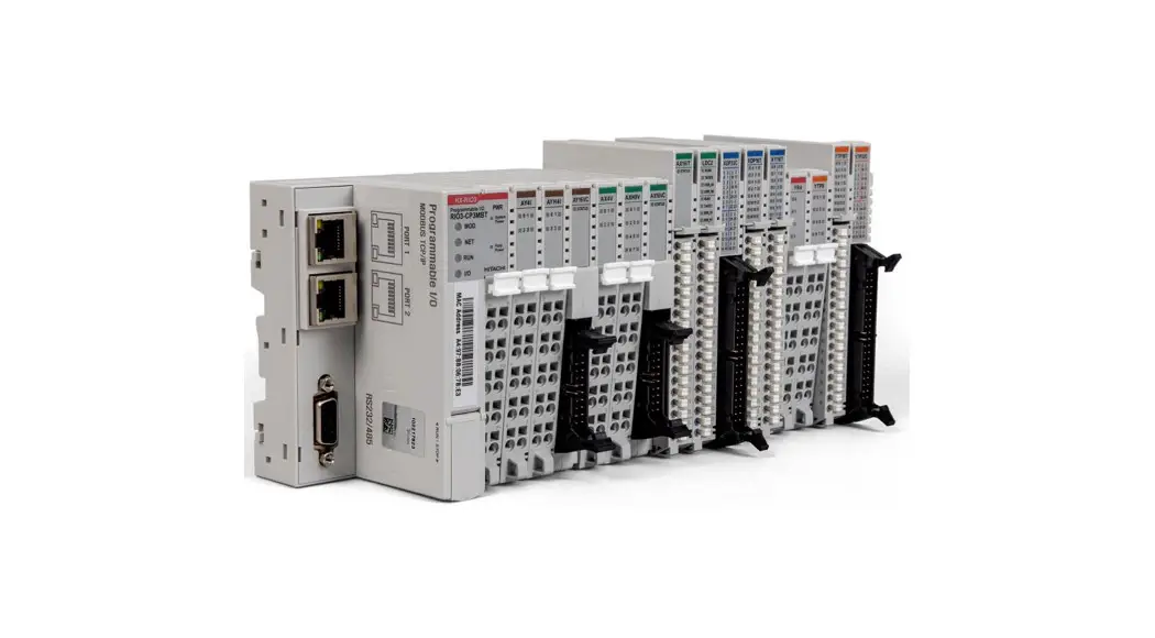
![]() HX-RIO3 Series Special IO Module
HX-RIO3 Series Special IO Module
User Manual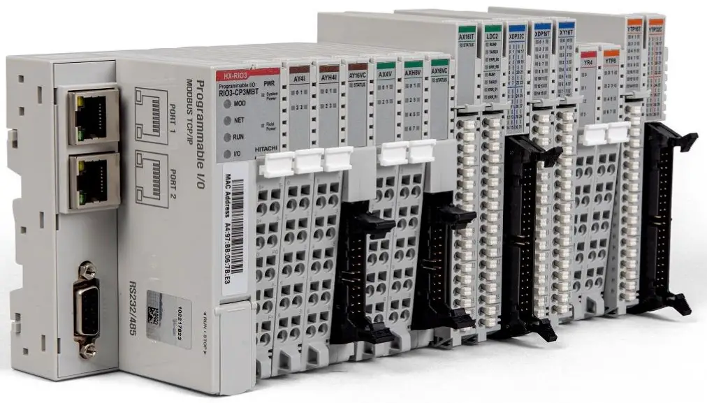
HX-RIO3 Series Special IO Module
| DOCUMENT REVISION | ||||
| REV | PAGE | REMARKS | DATE | EDITOR |
| 1.00 | New Document | Nov 2020 | (OPR), (PF) | |
| 1.00 | 17 | Remove product list table and add a reference | Aug 2021 | (PF) |
| 1.02 | 10 | Typo correction (B’ 1011 ( 0xB ), B’ 1100 ( 0xC )) | Jan 2022 | (PF) |
Important Notes
Solid state equipment has operational characteristics differing from those of electromechanical equipment. Safety Guidelines for the Application, Installation and Maintenance of Solid-State Controls describes some important differences between solid state equipment and hard-wired electromechanical devices.
Because of this difference, and because of the wide variety of uses for solid state equipment, all persons responsible for applying this equipment must satisfy themselves that each intended application of this equipment is acceptable.
In no event will HITACHI be responsible or liable for indirect or consequential damages resulting from the use or application of this equipment.
The examples and diagrams in this manual are included solely for illustrative purposes. Because of the many variables and requirements associated with any installation, HITACHI cannot assume responsibility or liability for actual use based on the examples and diagrams.
Warning!
✓ If you don’t follow the directions, it could cause a personal injury, damage to the equipment or explosion
✓ Do not assemble the products and wire with power applied to the system. Else it may cause an electric arc, which can result into unexpected and potentially dangerous action by field devices. Arching is explosion risk in hazardous locations. Be sure that the area is non-hazardous or remove system power appropriately before assembling or wiring the modules.
✓ Do not touch any terminal blocks or IO modules when system is running. Else it may cause the unit to an electric shock or malfunction.
✓ Keep away from the strange metallic materials not related to the unit and wiring works should be controlled by the electric expert engineer. Else it may cause the unit to a fire, electric shock or malfunction.
Caution!
✓ If you disobey the instructions, there may be possibility of personal injury, damage to equipmentor explosion. Please follow below Instructions.
✓ Check the rated voltage and terminal array before wiring. Avoid the circumstances over 50℃ of temperature. Avoid placing it directly in the sunlight.
✓ Avoid the place under circumstances over 85% of humidity.
✓ Do not place Modules near by the inflammable material. Else it may cause a fire.
✓ Do not permit any vibration approaching it directly.
✓ Go through module specification carefully, ensure inputs, output connections are made with the specifications. Use standard cables for wiring.
✓ Use Product under pollution degree 2 environment.
1.1 Safety Instruction
1.1.1 Symbols
| DANGER | Identifies information about practices or circumstances that can cause an explosion in a hazardous environment, which may lead to personal injury or death property damage, or economic loss. |
| IMPORTANT | Identifies information that is critical for successful application and understanding of the product. |
| ATTENTION | Identifies information about practices or circumstances that can lead to personal injury, property damage, or economic loss. Attentions help you to identity a hazard, avoid a hazard, and recognize the consequences |
1.1.2 Safety Notes
| DANGER | The modules are equipped with electronic components that may be destroyed byelectrostatic discharge. When handling the modules, ensure that the environment (persons, workplace and packing) is well grounded. Avoid touching conductive components, RBUS Pin. |
1.1.3 Certification
UL Listed Industrial Control Equipment, certified for U.S.
See UL File E196687
CE Certificate
EN 61000-6-2; Industrial Immunity
EN 61000-6-4; Industrial Emissions
Reach, RoHS (EU, CHINA), EAC
Specification
2.1 RIO3-CU24L
2.1.1 Wiring Diagram
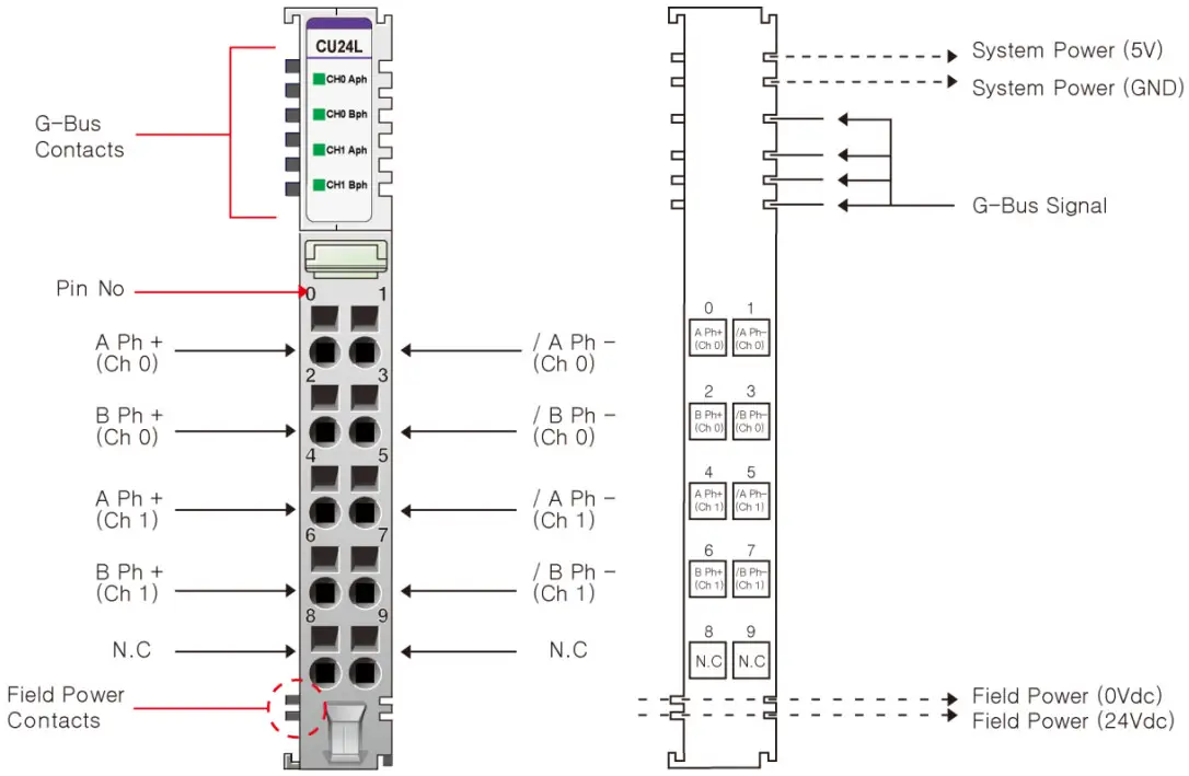
| Pin No. | Signal Description | Signal Description | Pin No. |
| 0 | A Ph Input+ Ch# 0 | A Ph Input- Ch# 0 | 1 |
| 2 | B Ph Input+ Ch# 0 | B Ph Input- Ch# 0 | 3 |
| 4 | A Ph Input+ Ch# 1 | A Ph Input- Ch# 1 | 5 |
| 6 | B Ph Input+ Ch# 1 | B Ph Input- Ch# 1 | 7 |
| 8 | Shield | Shield | 9 |
2.1.2 LED Indicator 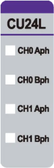
| LED No. | LED Function / Description | LED Color |
| 0 | Aph Input Ch# 0 | Green |
| 1 | Bph Input Ch# 0 | Green |
| 2 | Aph Input Ch# 1 | Green |
| 3 | Bph Input Ch# 1 | Green |
2.1.3 Channel Status LED
| Status | LED is | To indicate |
| No Signal | Off | Normal Operation |
| On Signal | Green | Normal Operation |
2.1.4 Specification
| Items | Specification |
| Input specification | |
| Number of channels | 2 channels – Encoder, High Speed Counter, Frequency measurement Pulse width & Period measurement |
| Indicators | 4 green terminal input |
| Input voltage | 24Vdc nominal (Max 28.8Vdc) |
| Input current | 3mA @ 24Vdc |
| Min on-state voltage | ≥16.5Vdc |
| Input frequency | 0~750kHz Encoder Mode 0~300kHz Counting Mode |
| Counting mode | 1- Input Mode: Up,Down 2- Input Mode: Encoder 4x, Encoder 2x, Up/Inhibit, Up/Reset, Down/Inhibit, Down/Reset, UP/Down, Clock/Direction, Frequency Measurement, Pulse Width & Period measurement |
| Counter size | 32bit-wide/channel |
| General specification | |
| Power dissipation | Max. 65mA @ 5Vdc |
| Isolation | I/O to Logic: Photocoupler isolation |
| UL field power | Supply Voltage: 24Vdc nominal, Class 2 |
| Field power | Not used Field power bypass to next expansion module |
| Wiring | I/O Cable Max. 2.0mm2 (AWG 14) |
| Torque | 0.8Nm (7 lb-in) |
| Weight | 60g |
| Module size | 12mm x 99mm x 70mm |
| Environment condition | Refer to ‘3. Environment Specification’ |
2.1.5 Mapping data into the image table
Input Image Data – 8byte
| Byte | Bit 7 | Bit 6 | Bit 5 | Bit 4 | Bit 3 | Bit 2 | Bit 1 | Bit 0 |
| 0 | Counter Value Ch#0 LL | |||||||
| 1 | Counter Value Ch#0 LH | |||||||
| 2 | Counter Value Ch#0 HL | |||||||
| 3 | Counter Value Ch#0 HH | |||||||
| 4 | Counter Value Ch#1 LL | |||||||
| 5 | Counter Value Ch#1 LH | |||||||
| 6 | Counter Value Ch#1 HL | |||||||
| 7 | Counter Value Ch#1 HH | |||||||
- Each channel has 4-byte Input
- Counter value represents counter, frequency (Hz), pulse width (0.1usec) or pulse period (0.1usec).
Output Image Data – 2byte
| Byte | Bit 7 | Bit 6 | Bit 5 | Bit 4 | Bit 3 | Bit 2 | Bit 1 | Bit 0 |
| 0 | CR 0 | CS 0 | — | — | Count Mode ch#0 | |||
| 1 | CR 1 | CS 1 | — | — | Count Mode ch#1 | |||
- CR 0,1: Counter Reset for Ch#0, Ch#1
- CS 0,1: Counter Stop (Inhibit Input) for Ch#0, Ch#1
- Count Mode Ch#0,1: Count Mode for Ch#0, Ch#1 respectively
Count Mode Ch#0, Ch#1
| Value | Count Mode | Description |
| B’ 0000 (0x0) | Up | Up Counter – Aph Input acts as Up Clock – Bph Input is not used |
| B’ 0001 (0x1) | Down | Down Counter – Aph Input acts as Down Clock – Bph Input is not used |
| B’ 0010 (0x2) | – | – |
| B’ 0011 (0x3) | – | – |
| B’ 0100 (0x4) | Up Clock & Inhibit | Up Counter with Inhibit – Aph Input acts as Up Clock Input – Bph Input acts as Inhibit function for Up Clock Input |
| B’ 0101 (0x5) | Up Clock & Reset | Up Counter with Reset – Aph Input acts as Up Clock Input – Bph Input acts as Reset function to Counter |
| B’ 0110 ( 0x6 ) | Down Clock & Inhibit | Down Counter with Inhibit – Aph Input acts as Down Clock Input – Bph Input acts as Inhibit function for Down Clock Input |
| B’ 0111 ( 0x7 ) | Down Clock & Reset | Down Counter with Reset – Aph Input acts as Down Clock Input – Bph Input acts as Reset function to Counter |
| B’ 1000 ( 0x8 ) | Up Clock & Down Clock | Up & Down Counter – Aph Input acts as Up Clock Input – Bph Input acts as Down Clock Input |
| B’ 1001 ( 0x9 ) | Clock & Direction | Up & Down with Direction – Aph Input acts as Clock Input – Bph Input acts as Direction Input ( Low = Up Count, High = Down Count ) |
| B’ 1010 ( 0xA ) | Encoder 1x (*1) | Encoder 1x – Aph Input acts as Encoder’s A phase Input – Bph Input acts as Encoder’s B phase Input |
| B’ 1011 ( 0xB ) | Encoder 2x | Encoder 2x – Aph Input acts as Encoder’s A phase Input – Bph Input acts as Encoder’s B phase Input |
| B’ 1100 ( 0xC ) | Encoder 4x | Encoder 4x – Aph Input acts as Encoder’s A phase Input – Bph Input acts as Encoder’s B phase Input |
| B’ 1101 ( 0xD ) | Frequency Measurement 1sec Update (*2) | Simple Frequency Measurement, updated by 1sec, Hz Unit – Aph Input acts as Frequency Input – Bph Input is not used |
| B’ 1110 ( 0xE ) | Pulse Width Measurement (*3) | Simple Pulse Width Measurement, 0.1usec Unit – Pulse Width(32bit), if 1234, then Pulse High(On) width is 123.4usec (*3) – Aph Input acts as Pulse Input – Bph Input is not used |
| B’ 1111 ( 0xF ) | Pulse Width & Period Measurement (*4) | Simple Pulse Width & Period Measurement, 0.1usec Unit, – Available in case of Pulse Input >= 200Hz(<= 2.5msec, Pulse On Width) – Pulse Width(16bit, Low Word) + Pulse Period(16bit, High Word) (*4) – Aph Input acts as Pulse Input – Bph Input is not used |
- Frequency Range of the Encoder x1 mode is the same as the counting mode.
- Frequency, B’1101 (0xD) can’t be used with other channel’s Count Mode = 0x0, 0x1, 0x4 ~ 0x9
- Pulse Width, B’1110 (0xE) measures Aph Input’s High (On) Pulse Width(32bit) in 0.1usec unit.
- Pulse Width & Period, B’1111 (0xF) measures Aph’s Pulse High (On) Width (16bit) & Period (16bit) in 0.1usec unit.
2.1.6 Configuration Parameter Data – 4byte
| Byte | Bit 7 | Bit 6 | Bit 5 | Bit 4 | Bit 3 | Bit 2 | Bit 1 | Bit 0 |
| 0 | Reserved | |||||||
| 1 | Reserved | |||||||
| 2 | Reserved | |||||||
| 3 | Reserved | |||||||
Environment Specification
| Environmental specification | |
| Operating Temperature | -20℃ ~ 70℃ |
| UL Temperature | -20℃ ~ 60℃ |
| Storage Temperature | -40℃ ~ 85℃ |
| Relative Humidity | 5% ~ 90% non-condensing |
| Mounting | DIN rail |
| General specification | |
| Shock Operating | IEC 60068-2-27: 2008/15g, 11ms |
| Vibration Resistance | Based on IEC 60068-2-6 DNVGL-CG-0039: Vibration Class B, 4g |
| Industrial Emissions | EN61000-6-4: 2007 +A1: 2011 |
| Industrial Immunity | EN61000-6-2: 2005 |
| Installation Position | Vertical and horizontal installation is possible |
| Product Certifications | CE, UL, EAC |
Dimension
4.1 10-Pts. Spring Type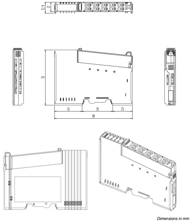
Mounting
Caution!
Hot surface!
The surface of the housing can become hot during operation. If the device was operated at high ambient temperatures, allow it to cool off before touching it.
Notice!
Perform work on devices only if they are de-energized!
Working on energized devices can damage them. Therefore, turn off the power supply before working on the devices.
5.1 I/O Inserting and Removing Devices
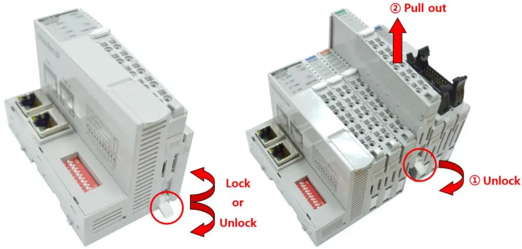
As above figure in order to safeguard the RIO3-Module from jamming, it should be fixed onto the DIN rail with locking lever. To do so, fold on the upper of the locking lever.
To pull out the RIO3-Module, unfold the locking lever as below figure.
5.2 RTB (Removable Terminal Block)
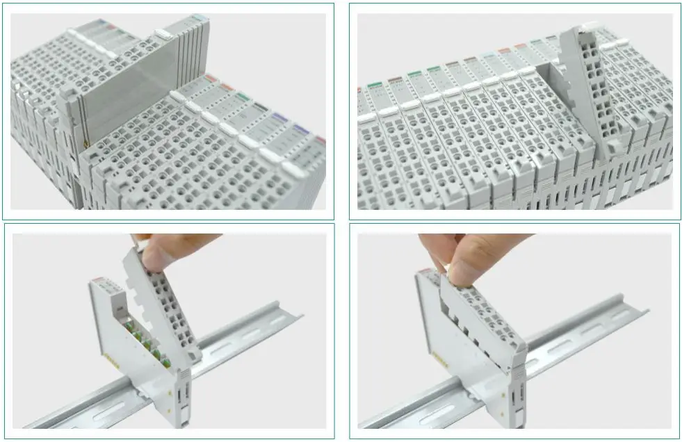 Whole terminal block can be combined and removed for the convenience if its maintenance.
There is a locking switch on the RTB for the easy combination and easy removal.
Easy combination and easy removal for IO modules on the din rail through One Touch Locking Switch.
G-Bus Pin Description
Communication between the Network Adapter and the expansion module as well as system/field power supply of the bus modules is carried out via the internal bus. It is comprised of 6 data pin and 2 field power pin.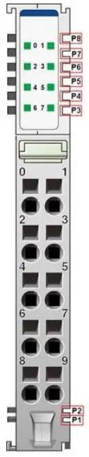 *Please refer to the table below regarding the pin description from P1 to P8.
| No. | Description |
| P1 | Field Power (VCC) |
| P2 | Field Power (GND) |
| P3 | GBUS CLK |
| P4 | GBUS MISO |
| P5 | GBUS MOSI |
| P6 | GBUS Token |
| P7 | System Power (GND) |
| P8 | System Power (VCC) |
| DANGER | Do not touch data and field power pins in order to avoid soiling and damage by ESD noise. |
APPENDIX A
7.1 Product List
Please refer the separate HX-RIO3 product list document
7.2 Glossary
System Power: The power for starting up CPU.
Field Power: The power for input and output line.
Terminator Resistor: Resistor for prevention reflected wave.
EDS: Electronic Data Sheet.
Sink: The method of in/output power supply if a device has no power source.
Source: The method of in/output power supply if a device has the power source.
![]() Version 1.02
Version 1.02


