![]() life.augmented
life.augmented
UM3030
User manual
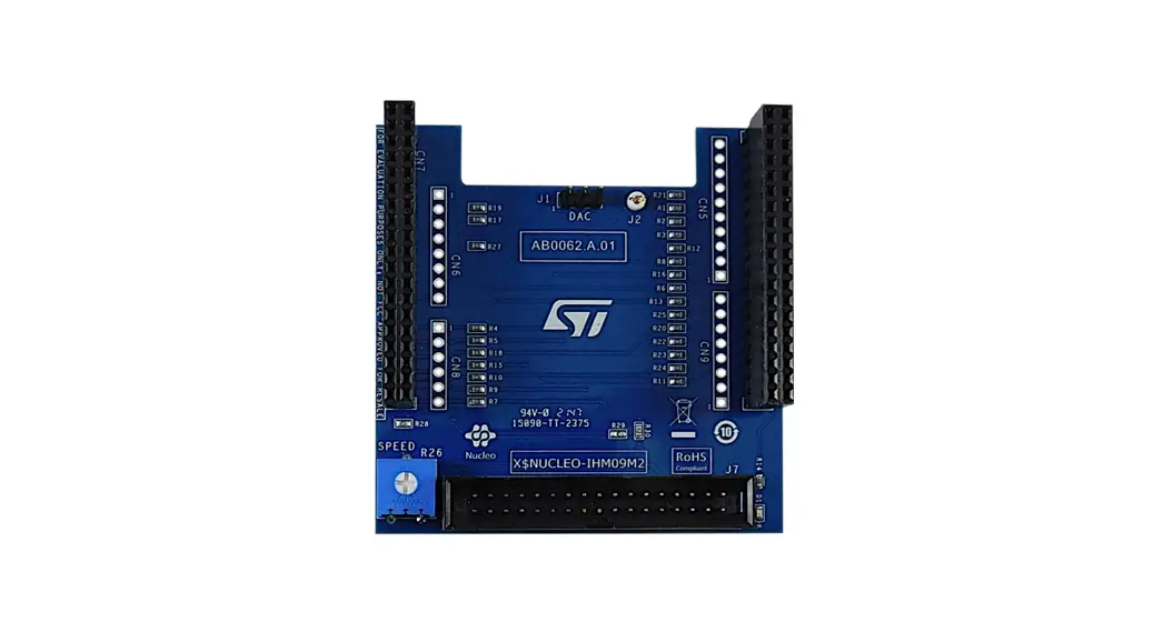
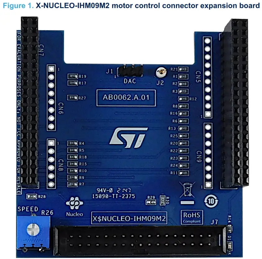
Getting started with the X-NUCLEO-IHM09M2 motor control connector expansion board for STM32 Nucleo
Introduction
The X-NUCLEO-IHM09M2 is a motor control connector expansion board for STM32 Nucleo. It provides an easy way to evaluate motor control solutions for three-phase motors by connecting the STM32 Nucleo development board to an external ST motor control power board, thanks to the ST morpho and motor control connector.
The 34-pin motor control connector is compatible with all major ST motor control power boards, which require an external digital section (MCU) to drive a three-phase motor.
The DAC connector supports the user code development and testing with easy access to the MCU peripherals. An LED is available for fault condition signaling or status indication. The X-NUCLEO-IHM09M2 is fully compatible with the ST six-step and field-oriented control (FOC) firmware library.
System Overview
1.1 Main characteristics
The X-NUCLEO-IHM09M2 expansion board is designed for three-phase motor driver applications. It features:
- ST motor control connector (34 pins) compatible with ST motor control power boards
- STM32 Nucleo compatibility, thanks to ST morpho connectors
- Compatible with the ST six-step and FOC motor control firmware library
- Debug connector for DAC, GPIOs, etc.
- Fully populated board with test points
- LED for fault signaling or status indication
- Potentiometer available (for speed reference)
- PCB type and size:
– PCB material – FR-4
– layout – double layer
– copper thickness – 35 μm
– overall board dimensions – 70 mm x 70 mm - RoHS compliant
Getting started
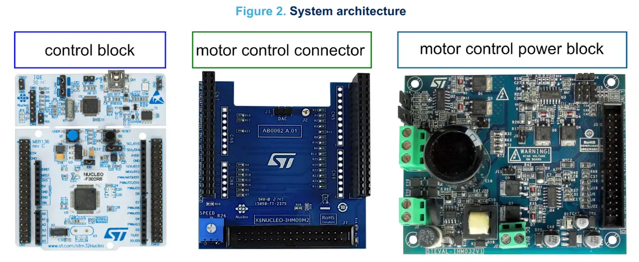
2.1 System architecture
A generic motor control system consists of the following major blocks:
- Control block, which accepts the user commands and provides motor control signals to drive a motor. The X-NUCLEO-IHM09M2 adapter connects an STM32 Nucleo development board to a power board that requires an external digital section.
- Power block, which is normally in a three-phase inverter topology. It contains all the necessary active power
- Motor, which is a three-phase brushless motor.
2.2 Building the system
The X-NUCLEO-IHM09M2 expansion board adapts the STM32 Nucleo development board to the ST motor control power boards, which require an external digital section to control a three-phase PMSM/BLDC motor. For the regular board operation, plug the expansion board onto the top of the development board (control block) via the ST morpho connector, as shown below.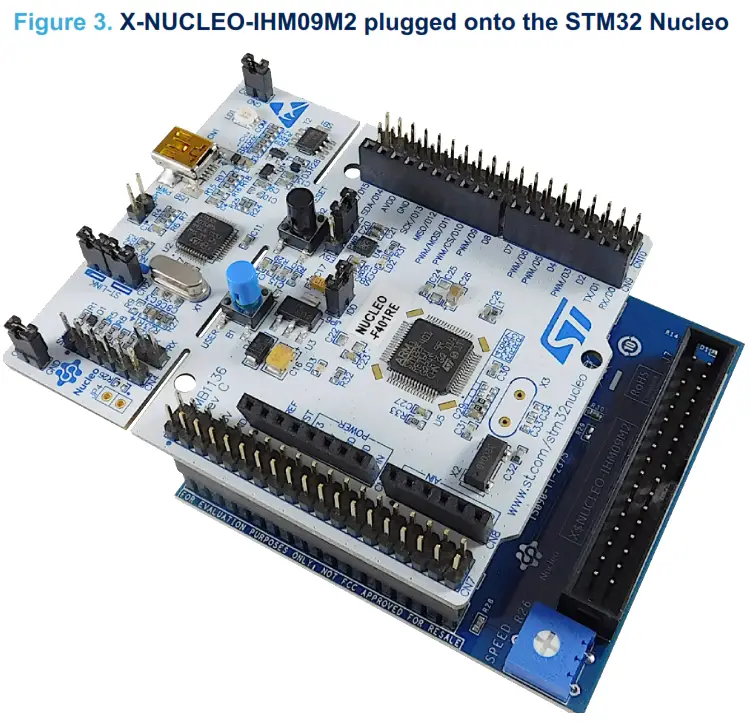 The interconnection between the two boards is fully compatible with a wide range of STM32 Nucleo development boards. No solder bridge modification is required. The stacked solution is ready to operate with a compatible power board via a standard 34-pin flat cable.
2.2.1 Hardware settings
Set the X-NUCLEO-IHM09M2 J1 jumper off.
Table 1. Jumper, connectors, and LED
| Jumper/connector | Description |
| J7 | 34-pin motor control connector |
| J1 | DAC/GPIO output |
| CN7 | ST morpho connector |
| CN6 | Arduino UNO R3 connector |
| CN8 | Arduino UNO R3 connector |
| CN10 | ST morpho connector |
| CN5 | Arduino UNO R3 connector |
| CN9 | Arduino UNO R3 connector |
| D1 | LED for fault or status indication |
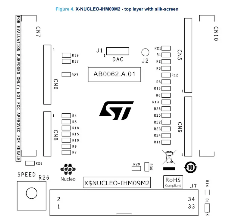
The X-NUCLEO-IHM09M2 is equipped with ST morpho connectors. The male pin headers are CN7 and CN10. These connectors are used to connect the expansion board to the STM32 Nucleo. The MCU signals and power pins are available on the morpho connector. For further details, refer to UM1724, section 5.12.
Table 2. ST morpho connector – CN7
| Pin | Default | Signal | Solder bridge |
| 1 | PC10 | NTC bypass | R17 |
| 2 | PC11 | Dissipative brake/OCP disable | R19 |
| 3 | PC12 | ||
| 4 | PD2 | ||
| 5 | VDD | ||
| 6 | E5V | ||
| 7 | BOOT0 | ||
| 8 | GND | ||
| 9 | NC/PF6 |
| 10 | NC |
| 11 | NC/PF7 | ||
| 12 | MORE | ||
| 13 | PA13 | ||
| 14 | RESET | ||
| 15 | PA14 | ||
| 16 | +3V3 | ||
| 17 | PA15 | Encoder A/Hall H1 | R27 |
| 18 | +5V | ||
| 19 | GND | ||
| 20 | GND | ||
| 21 | PB7 | ||
| 22 | GND | ||
| 23 | PC13 | ||
| 24 | VIN | ||
| 25 | PC14 | ||
| 26 | NC | ||
| 27 | PC15 | ||
| 28 | PAO | Curr fdbk_PhA | R4 |
| 29 | PHO/PFO/PDO | ||
| 30 | PA1 | VBUS_sensing | R5 |
| 31 | PH1/PF1/PD1 | ||
| 32 | PM | DAC_Ch | R18 (not mounted) |
| 33 | VLCDNBAT | ||
| 34 | PBO | VL_PWM | R15 |
| 35 | PC2 | Temperature feedback | R10 |
| 36 | PC1 or PB9 | Cur fdbk_PhB | R9 (0) |
| 37 | PC3 | Potentiometer | R28 |
| 38 | PCO or PB8 | Cur fdbk_PhC | R7 (0) |
For further details, refer to UM1724, table 9.
Table 3. ST morpho connector – CN10
| Pin | Default | Signal | Solder bridge |
| 1 | PC9 | ||
| 2 | PC8 | ||
| 3 | PB8 | ||
| 4 | PC6 | ||
| 5 | PB9 | ||
| 6 | PC5 | ||
| 7 | ADD | ||
| 8 | U5V -1 |
| Pin | Default | Stoma! | Solder bridoe |
| 9 | GND | ||
| 10 | NC | ||
| 11 | pA5 (2) | GPIOIDAC/PWM | R21 |
| 12 | PAl2 | ||
| 13 | PA6 (3) | DIAG/ENABLE/BKIN1 | R3 |
| 14 | PA11 | DIAG/ENABLE/BKIN2 | R1 |
| 15 | PA7 0) | UL_PWM | R12 |
| 16 | PB12 | ||
| 17 | PB6 | ||
| 18 | PBIIINC | ||
| 19 | PC7 | ||
| 20 | GND | ||
| 21 | PM | VH_PWM | R8 |
| 22 | PB2 | Red LED | R14 |
| 23 | PM | UH_PWM | R6 |
| 24 | PB1 | WL_PWM | R16 |
| 25 | PB10 | Encoder Z/Hall H3 | R25 |
| 26 | PB15 (4) | ||
| 27 | PB4 | PVVM/DEBUG | R20 |
| 28 | PB14 (3) | DIAG/ENABLE/BKIN1 | R2 |
| 29 | PB5 | GPIO/DAC/PWM | R23 |
| 30 | PB13 (2) | GPIO/DAC/PWM | R22 |
| 31 | PB3 | Encoder B/Hall H2 | R24 |
| 32 | AGND | ||
| 33 | PA10 | WH_PWM | R11 |
| 34 | PC4 | ||
| 35 | PA2 | ||
| 36 | NC/PF5 | ||
| 37 | PA3 | ||
| 38 | NC/PF4 |
- U5V is the 5 V power from the ST-LINK/V2-1 USB connector and it rises above +5 V.
- For NUCLEO-F302R8 only: pin PA5 is on CN10/pin 30 and PB13 is on CN10/pin 11.
- For NUCLEO-F302R8 only: pin PA6 is on CN10/pin 28 and PB14 is on CN10/pin 13.
- For NUCLEO-F302R8 only: pin PA7 is on CN10/pin 26 and PB15 is on CN10/pin 13.
2.2.2 Pinout of the motor control connector
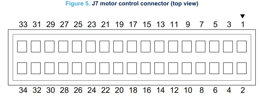
The X-NUCLEO-IHM09M2 expansion board supports motor control via the J7 34-pin connector. This connector provides all the required control and feedback signals to and from an ST motor power-drive board. The available signals include the emergency stop, speed or position feedback, three-phase motor current, bus voltage, and heatsink temperature.
Table 4. J7 pin assignments
| Pin | Default | Function |
| 1 | PA6/PA11 | DIAG/ENABLE/BKIN1 |
| 2 | GND | Dissipative brake/OCP disable |
| 3 | PM | UH_PWM |
| 4 | GND | |
| 5 | PA7/PB15 | UL_PWM |
| 6 | GND | |
| 7 | PM | VH_PWM |
| 8 | GND | |
| 9 | PBO | VL_PWM |
| 10 | GND | |
| 11 | PA10 | WH_PWM |
| 12 | GND | |
| 13 | PB1 | WL_PWM |
| 14 | PA1 | VBUS_sensing |
| 15 | PM | Curr fdbk PhA |
| 16 | Not connected | |
| 17 | PC1 | Curr fdbk_PhB |
| 18 | Not connected | |
| 19 | PCO | Curr folk PhC |
| 20 | Not connected | |
| 21 | PC10 | NTC bypass |
| 22 | Not connected | |
| 23 | PC11 | Dissipative brake/OCP disable |
| Pin | Default | Function |
| 24 | Not connected | |
| 25 | E5V | |
| 26 | PC2 | Temperature feedback |
| 27 | Not connected | |
| 28 | Not connected | |
| 29 | Not connected | |
| 30 | Not connected | |
| 31 | PA15 | Encoder A/Hall H1 |
| 32 | Not connected | |
| 33 | PB3 | Encoder B/Hall H2 |
| 34 | PB10 | Encoder Z/HaII H3 |
2.2.3 DAC settings for debug
For debugging purposes, you can use the DAC peripheral and configure the motor control library to drive the signal. For instance, the PA4 pin is accessible through the ST morpho connector or J1 connector. This pin is usually connected to DAC_CH1. Different pins are available on the J1 connector, according to the STM32 Nucleo development board used.
2.2.4 User LED
The X-NUCLEO-IHM09M2 provides a programmable LED (D1) connected on the PB2 pin. It can be used to signal motor status, faults, etc. You have to configure this pin and drive it through the application code you have developed.
MC FOC SDK: configuration guide for X-NUCLEO-IHM09M2
The X-NUCLEO-IHM09M2 expansion board is compatible with the motor control (MC) FOC SDK, which is a firmware library and workbench GUI. No hardware modification is needed to run the motor through this control algorithm. For the pin configuration, see Table 2 and Table 3. You can connect the STM32 Nucleo to the MC workbench GUI through a virtual COM embedded in the STM32 Nucleo, which allows using the USART2 on PA2 and PA3 pins from the same USB type A to Mini-B USB cable used to program the STM32 Nucleo. For further information on the MC FOC SDK, see X-CUBE-MCSDK.
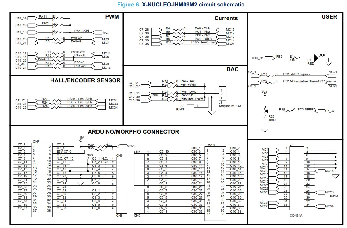
Schematic diagrams
Bill of materials
Table 5. X-NUCLEO-IHM09M2 bill of materials
| Item | Q.ty | Ref. | Part/value | Description | Manufacturer | Order code |
| 1 | 1 | D1 | RED, SMD 0603, | LED standard – SMD | Lite-on | LATEST-C193KRKT-5A |
| 2 | 1 | J1 | Stripline m. 1×3, TH 2.54 mm pitch | 3-way strip line | Stelvio Kontek | 613040167028 |
| 3 | 1 | J2 | RING, TH, 1mm | Test point | Vero Technologies | 20-2137 |
| 4 | 2 | CN7, CN10, male on top, female on the bottom | CONN 38, TH 2.54 mm pitch | 38-pin elevated socket morpho connector | Samtec | ESQ-119-24-T-D |
| 4UCONN | 08413 | |||||
| 5 | 0 | CN6, CN9,female on top, male on the bottom | CONN8, TH 2.54 mm pitch | 8-pin elevated socket morpho connector (not mounted) | Samtec | ESQ-108-24-T-S |
| 4UCONN | 15284 | |||||
| 6 | 0 | CN5, female on top, male on the bottom | CONN10, TH 2.54 mm pitch | 10-pin elevated socket (not mounted) | Samtec | ESQ-110-24-T-S |
| 4UCONN | 15286 | |||||
| 7 | 1 | J7 | Motor control connector, TH | 34-way IDC straight boxed header | ASSMANN WSW | AWHW 34G-0202-T |
| 8 | 0 | CN8, female on top, male on the bottom | CONN6, TH 2.54 mm pitch | 6-pin elevated socket (not mounted) | Samtec | ESQ-106-24-T-S |
| 4UCONN | 15282 | |||||
| 9 | 26 | R1, R2, R3, R4,R5, R6, R7, R8, R9, R10, R11, R12, R13, R15, R16, R17, R18, R19, R20, R21, R22, R23, R24, R25, R27, R28 | 0 Ohm, 0603,0.1 W | SMD resistors | RS PRO | 716-9743 |
| 10 | 1 | R14 | 510 Ohm, 0603,0.1 W | SMD resistor | RS PRO | 804-8820 |
| 11 | 1 | R26 | 100 kOhm, 1/2 W, ±10 % | Trimmer resistor | Bourns | 3386G-1-104LF |
| 12 | 0 | R29 | 0, 0603, 1/2 W | Solder bridge (not mounted) – leave open | – | – |
| 13 | 1 | R30 closed with a drop of tin | 0, 0603, 1/2 W | Solder bridge | Any | – |
Board versions
Table 6. X-NUCLEO-IHM09M2 versions
| PCB version | Schematic diagrams | Bill of materials |
| X$NUCLEO-IHM09M2 (1) | X$NUCLEO-IHM09M2 schematic diagrams | X$NUCLEO-IHM09M2 bill of materials |
1. This code identifies the X-NUCLEO-IHM09M2 first version. It is printed on the board PCB.
Regulatory compliance information
Formal Notice Required by the U.S. Federal Communications Commission
For evaluation only; not FCC approved for resale
FCC NOTICE
This kit is designed to allow:
- Product developers to evaluate electronic components, circuitry, or software associated with the kit to
determine whether to incorporate such items in a finished product and - Software developers write software applications for use with the end product.
This kit is not a finished product and when assembled may not be resold or otherwise marketed unless all required FCC equipment authorizations are first obtained. Operation is subject to the condition that this product does not cause harmful interference to licensed radio stations and that this product accepts harmful interference. Unless the assembled kit is designed to operate under part 15, part 18 or part 95 of this chapter, the operator of the kit must operate under the authority of an FCC license holder or must secure an experimental authorization under part 5 of this chapter 3.1.2.
Formal Product Notice Required by Industry Canada Innovation, Science and Economic Development Canada compliance:
For evaluation purposes only. This kit generates, uses, and can radiate radio frequency energy and has not been tested for compliance with the limits of computing devices pursuant to Industry Canada (IC) rules.
Formal product notice required by the EU
This device is in conformity with the essential requirements of Directive 2015/863/EU (RoHS).
Revision history
Table 7. Document revision history
| Date | Revision | Changes |
| 18-Jul-2022 | 1 | Initial release. |
IMPORTANT NOTICE – READ CAREFULLY
STMicroelectronics NV and its subsidiaries (“ST”) reserve the right to make changes, corrections, enhancements, modifications, and improvements to ST products and/or to this document at any time without notice. Purchasers should obtain the latest relevant information on ST products before placing orders. ST products are sold pursuant to ST’s terms and conditions of sale in place at the time of order acknowledgment.
Purchasers are solely responsible for the choice, selection, and use of ST products and ST assumes no liability for application assistance or the design of purchasers’ products.
No license, express or implied, to any intellectual property right is granted by ST herein.
Resale of ST products with provisions different from the information set forth herein shall void any warranty granted by ST for such product.
ST and the ST logo are trademarks of ST. For additional information about ST trademarks, refer to www.st.com/trademarks. All other product or service names are the property of their respective owners.
Information in this document supersedes and replaces information previously supplied in any prior versions of this document.
© 2022 STMicroelectronics – All rights reserved
UM3030 – Rev 1![]()
References
 STMicroelectronics: Our technology starts with you
-
STMicroelectronics Trademark List - STMicroelectronics
-
NUCLEO-F302R8 - STM32 Nucleo-64 development board with STM32F302R8 MCU, supports Arduino and ST morpho connectivity - STMicroelectronics
-
X-CUBE-MCSDK - STM32 Motor Control Software Development Kit (MCSDK) - STMicroelectronics
-
X-NUCLEO-IHM09M2 - Motor control connector expansion board for STM32 Nucleo - STMicroelectronics
-
STM32 Nucleo Boards - STMicroelectronics


