SIEMENS 7SR45 Communication Protocol
Product Information
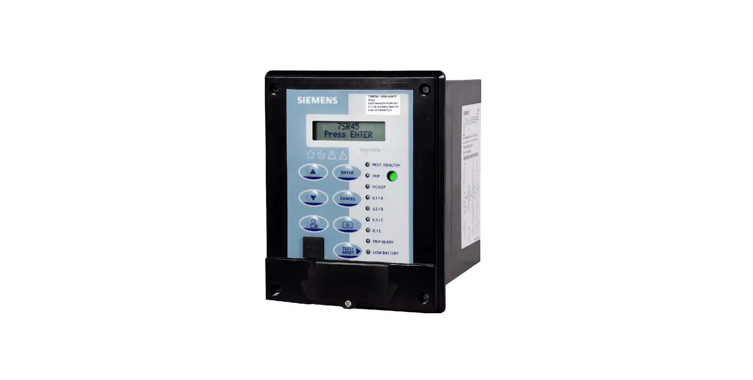
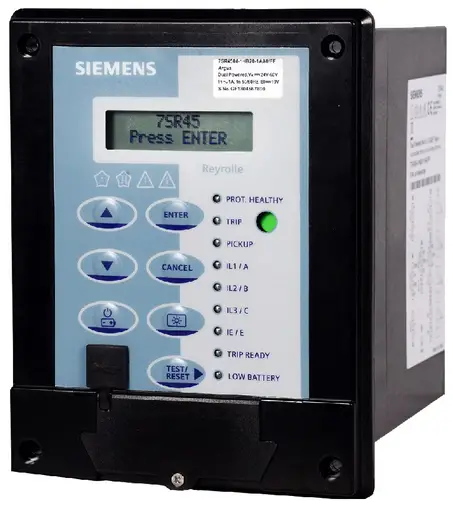
- Product Name: Reyrolle 7SR5 device family
- Document Version: C53000-L7040-C101-3.0
- Product Version: V03.00
- Target Audience: Protection system engineers, commissioning engineers, persons entrusted with the setting, testing and maintenance of automation, selective protection and control equipment, and operational crew in electrical installations and power plants.
- Scope: This manual applies to the Reyrolle 7SR5 device family.
- Description: The Reyrolle 7SR5 device family is a protection device used in electrical installations and power plants. It includes communication modules that support Modbus RTU and IEC 60870-5-103 protocols for communication within the device family and to higher-level network control centers.
Product Usage
The Reyrolle 7SR5 device family is designed to be used by protection system engineers, commissioning engineers, persons entrusted with the setting, testing and maintenance of automation, selective protection and control equipment, and operational crew in electrical installations and power plants. The device family includes communication modules that support Modbus RTU and IEC 60870-5-103 protocols for communication within the device family and to higher-level network control centers.
Before using the device, users should read the user manual carefully to understand the safety instructions and warnings contained in the document. Users should also ensure that they have the appropriate knowledge and training to operate the device.
The device manual describes the functions and applications of the Reyrolle 7SR5 device, while the hardware manual describes the hardware building blocks and device combinations of the device family. The operating manual provides the basic principles and procedures for operating and installing the devices, while the communication protocol manual contains a description of the protocols for communication within the device family and to higher-level network control centers. The security manual describes the security features of the devices and Reydisp Manager 2, while the engineering guide describes the essential steps when engineering with Reydisp Evolution.
If users have any questions about the system or need additional support, they can contact their Siemens sales partner or the Customer Support Center, which provides a 24-hour service by phone or email.
Preface
Purpose of the Manual
This manual contains information about:
- Communication within the Reyrolle 7SR5 device family and to higher-level control centers
- Setting parameters in Reydisp Manager
- Information on commissioning
Target Audience
This manual is mainly intended for protection system engineers, commissioning engineers, persons entrusted with the setting, testing and maintenance of automation, selective protection and control equipment, and operational crew in electrical installations and power plants.
Scope
This manual applies to the Reyrolle 7SR5 device family.
Further Documentation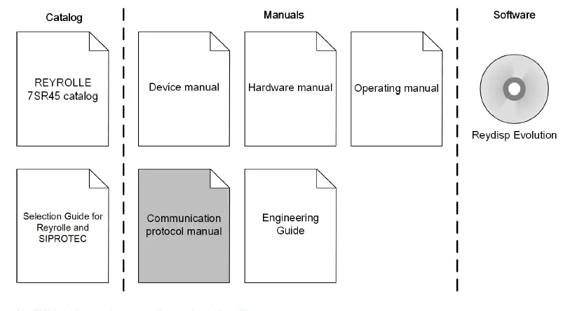
- Device manual
The device manual describes the functions and applications of the Reyrolle 7SR45 device. The printed manual for the device has the same informational structure. - Hardware manual
The hardware manual describes the hardware building blocks and device combinations of the Reyrolle 7SR45 device family. - Operating manual
The operating manual describes the basic principles and procedures for operating and installing the devices of the Reyrolle 7SR45 range. - Communication protocol manual
The communication protocol manual contains a description of the protocols for communication within the Reyrolle 7SR45 device family and to higher-level network control centers. - Security manual
The security manual describes the security features of the Reyrolle 7SR45 devices and Reydisp Manager 2. - Engineering Guide
The engineering guide describes the essential steps when engineering with Reydisp Evolution. In addition, the engineering guide shows you how to load a planned configuration to a Reyrolle Communication Protocol device and update the functionality of the Reyrolle Communication Protocol device. - Reyrolle 7SR45 catalog
The Reyrolle 7SR45 catalog describes the system features and the devices of Reyrolle 7SR45. - Selection guide for Reyrolle and SIPROTEC
The selection guide offers an overview of the device series of the Siemens protection devices, and a device selection table.
Additional Support
For questions about the system, contact your Siemens sales partner.
Customer Support Center
Our Customer Support Center provides a 24-hour service.
- Siemens AG
- Smart Infrastructure – Digital Grid Phone: +49 911 2155 4466
- Customer Support Center E-mail: [email protected]
Training Courses
Inquiries regarding individual training courses should be addressed to our Training Center:
- Siemens AG
- Siemens Power Academy TD Phone: +49 911 9582 7100
- Humboldtstraße 59 E-mail: [email protected]
- 90459 Nuremberg Internet: www.siemens.com/poweracademy
Notes on Safety
This document is not a complete index of all safety measures required for operation of the equipment (module or device). However, it comprises important information that must be followed for personal safety, as well as to avoid material damage. Information is highlighted and illustrated as follows according to the degree of danger:
- DANGER means that death or severe injury will result if the measures specified are not taken.
- Comply with all instructions, in order to avoid death or severe injuries.
- WARNING means that death or severe injury may result if the measures specified are not taken.
- Comply with all instructions, in order to avoid death or severe injuries.
- CAUTION means that medium-severe or slight injuries can occur if the specified measures are not taken.
- Comply with all instructions, in order to avoid moderate or minor injuries.
- NOTICE means that property damage can result if the measures specified are not taken.
- Comply with all instructions, in order to avoid property damage.
- NOTE Important information about the product, product handling or a certain section of the documentation which must be given attention.
OpenSSL
This product includes software developed by the OpenSSL Project for use in OpenSSL Toolkit (http://www.openssl.org/).
This product includes software written by Tim Hudson ([email protected]).
This product includes cryptographic software written by Eric Young ([email protected]).
Open Source Software
The product contains, among other things, Open Source Software developed by third parties. The Open Source Software used in the product and the license agreements concerning this software can be found in the Readme_OSS. These Open Source Software files are protected by copyright. Your compliance with those license conditions will entitle you to use the Open Source Software as foreseen in the relevant license. In the event of conflicts between Siemens license conditions and the Open Source Software license conditions, the Open Source Software conditions shall prevail with respect to the Open Source Software portions of the software. The Open Source Software is licensed royalty-free. Insofar as the applicable Open Source Software License Conditions provide for it you can order the source code of the Open Source Software from your Siemens sales contact – against payment of the shipping and handling charges – for a period of at least 3 years after purchase of the product. We are liable for the product including the Open Source Software contained in it pursuant to the license conditions applicable to the product. Any liability for the Open Source Software beyond the program flow intended for the product is explicitly excluded. Furthermore, any liability for defects resulting from modifications to the Open Source Software by you or third parties is excluded. We do not provide any technical support for the product if it has been modified.
The ReadmeOSS documents for the product can be found here: www.siemens.com/reyrolle.
Communication Modules
Overview
The relay data communication facility is compatible with control and automation systems and PCs running Reydisp software. The relay can provide the following:
- Operational information
- Post-fault analysis
- Settings interrogation
- Editing facilities
This section describes how to use the communication interface with a control system or interrogating computer. An appropriate software application within the control system or on the interrogating computer (for example, Reydisp Evolution) is required to access the interface. The relay data communication facility incorporates the protocols selected by you and provides compatibility with control and automation systems. This section specifies connection details and lists the events, commands, and measurand available in the IEC 60870-5-103 and Modbus RTU protocols. The communication interface for dialog communication by the protection engineer is provided by the Reydisp Evolution software packages using the IEC 60870-5-103 protocol. You can download the configuration software from www.siemens.com/reyrolle. This section specifies connection details and lists the information available through the individual protocols.
NOTE The 7SR45 Argus Dual Powered Relay variant supports the data communication.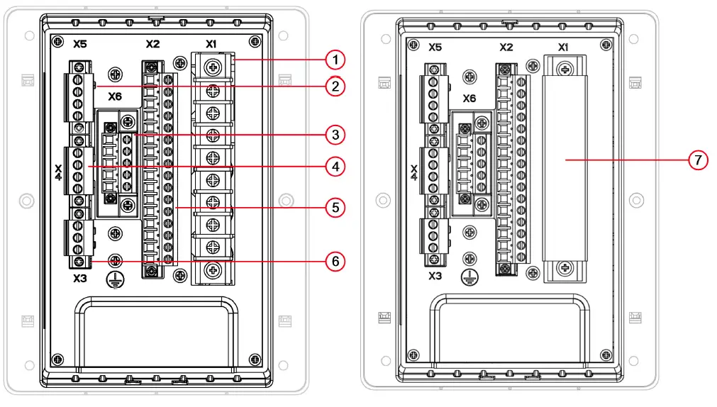
- Current inputs
- Additional binary inputs
- Additional binary outputs
- Rear communication port
- Binary inputs/binary outputs/flag output/pulse output
- Auxiliary power supply
- IP20 Cover for current terminals
The relay range provides 1 front USB communication interface (Com2) on the fascia and 1 RS485 (Com1) on the rear. The access to the communication settings for the USB port & the RS485 port is available from the relay front via the keypad setting COMMUNICATION menu. The communication settings for the RS485 port can also be done through Reydisp Evolution via the USB connections.
Communication interface
- The Com2-USB port can be used for IEC 60870-5-103 or Modbus RTU communication. The Com2-USB port is used for IEC 60870-5-103 (default setting) communication with the Reydisp Evolution software. The ASCII protocol allows to update the firmware via the front connection.
- Com1-RS485
The Com1-RS485 port can be used for IEC 60870-5-103 or Modbus RTU communications to a substation SCADA, integrated control system, or engineer remote access.
Any or all serial ports can be mapped to the IEC 60870-5-103 or MODBUS RTU protocol at any one time, protocols available will depend upon relay model. When connecting to Reydisp Evolution software, Siemens recommends setting the IEC 60870-5-103 protocol for the relevant port.
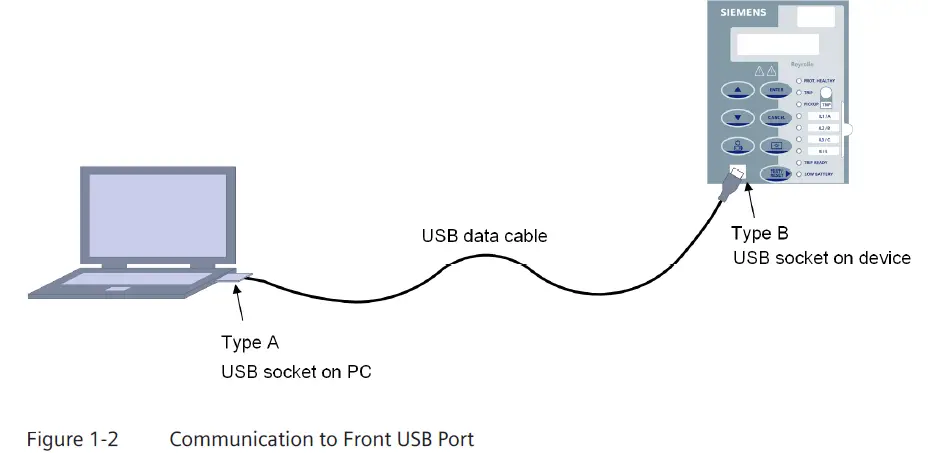
USB Communication Interface (Com2)
The USB communication port is connected to the relay using a standard USB cable type B and to the PC using a standard USB cable type A. When Reydisp Evolution software is installed, a suitable USB driver is installed in the PC automatically. When Reydisp Evolution software is running with the USB cable connected to a device, an additional connection is shown in the Reydisp connection window. The connections to these devices are not shown when they are not connected. The USB communication interface on the relay and its associated settings are located in the COMMUNICATION menu. When connecting to Reydisp Evolution using this connection, the default settings can be used without changing any settings.
Table 1-1 USB Interface (Com2)
| Setting Name | Range/Options | Default | Setting | Notes |
| USB‑Protocol | OFF IEC60870‑5‑103 MODBUS‑RTU | IEC60870‑5‑103 | – | The Reydisp Evolution soft- ware requires IEC60870‑5‑103. |
| USB‑Stn Addr | 0 to 254 for IEC60870‑5‑103 1 to 247 for MODBUS‑RTU | 1 | – | To identify the relay, provide an address within the range of the relevant protocol. Each relay in a network must have a unique address. |
| USB‑Mode | Local Local or Remote Remote | Local or Remote | – | – |
RS485 Connection (Com1)
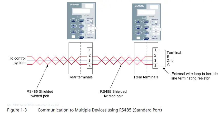
The 2 wire RS485 communication port is located on the rear of the relay and can be connected using a suitable RS485 120 Ω shielded twisted pair cable.
The RS485 electrical connection can be used in a single or multi-drop configuration. The RS485 master must support and use the Auto Device Enable (ADE) feature. The last device in the connection must be terminated correctly in accordance with the master device driving the connection. The connection can be done via the internal 120 Ω load resistor, which can be connected between (A) and (B) by fitting an external wire loop between terminals 1 and 4 on the X4 connector.
The polarity of the signal terminals is marked as A and B which is in line with the RS485 standard. When the bus is in the idle state and no communication is taking place, the polarity of terminal A is more positive than that of terminal B. These terminals can be used to identify the polarity of any equipment to be connected, typically measured at each terminal in turn to earth. Figure 1-3 shows the connection of the device to a termination network at the end of the bus and suits the idle state.
The polarity marking is often found to be reversed or marked as ± on other equipment, so care is required. If the devices are connected in reverse, then communication to all devices is disturbed without any damage. If problems are experienced during commissioning, perform the connections in reverse. The maximum number of relays that can be connected to the bus is 32.
When using the RS485 interface, you must configure the following settings in the following settings on the COMMUNICATION menu:
Table 1-2 RS485 Interface (Com1)
| Setting Name | Range/Options | Default | Setting | Notes |
| RS485–Protocol | OFF IEC60870–5–103 MODBUS–RTU | MODBUS–RTU | – | The protocol is used to communicate on the standard RS485 connec- tion. |
| RS485–Stn Addr | 0 to 254 for IEC60870–5– 103 1 to 247 for MODBUS–RTU | 1 | – | To identify the relay, provide an address within the range of the relevant protocol. Each relay in a network must have a unique address. |
| RS485–Baud Rate | 1200 2400 4800 9600 19200 38400 57600 | 19200 | – | The baud rate set on all the relays connected to the control system must be the same as the one set in accordance with the master device. |
| RS485–Parity | None Odd Even | None | – | The parity set on all the relays connected to the control system must be the same as the one set in accordance with the master device. |
| RS485–Mode | Local Local or Remote Remote | Local or Remote | – | – |
Modbus RTU
Protocol Characteristics
Description
This section describes the Modbus RTU protocol implementation in the 7SR45 Argus relay. The Modbus RTU protocol is used for communication with a suitable control system. The Modbus RTU protocol can be set to use any number of relay hardware interfaces (USB, RS485) where it is installed. The relay can communicate simultaneously on all ports regardless of the protocol used. To enable the communication, set the station address of the port used to a suitable address within a range of 1 to 247. You can set the station address using the xxxxx-Stn Addr setting under COMMUNICATION menu.
- Protocol Structure
- Modbus Registers
Modbus registers are 16-bit registers which do not have any standard for use. Multiple registers are used to hold a data value. This section describes the Modbus data types. If a data type occupies more than 1 register, it is required that the number of consecutive registers are reserved. For example, if a 2 register data point starts at 30101, then it is required that register 30102 is also reserved so that the next available register would be 30103. The following table shows the number of registers required for each data type.Data Type Registers Required EVENTCOUNT 1 EVENT 8 FP_32BITS_3DP 2 UINT16 1 UINT32 2 STR32 16 STR64 32 TIME_METER 4
- Modbus Registers
- Data Types
- EVENTCOUNT
A single register containing the number of event records stored. - EVENT
Modbus does not define a method for extracting the events, therefore a private method has been defined based on that defined by in IEC 60870-5-103.
The EVENTCOUNT register contains the current number of events in the relays operational log. The EVENT register contains the earliest event record available. The event record is 8 registers (16 bytes) of information and the format is described under Format , Page 21. When this record is read, then the event is replaced by the next available record. Event records must be read completely, therefore the quantity value must be set to 8 before reading.- FP_32BITS_3DP
A real value transmitted as a 32-bit integer scaled and fixed point to 3 decimal places. For example, 123.456 would be sent as 123456. - UINT16
A 16-bit integer. - UINT32
A 32-bit integer. - STR32
A 32 byte string. - STR64
A 64 byte string. - TIME_METER
Table 2-1 shows 4 register (8 byte) time meter formatted.
Table 2-1 Fields in the Time MeterByte Key Description 0 ms L Milliseconds low byte 1 ms H Milliseconds high byte 2 Mi Minutes (MSB = invalid, time not set > 23 h) 3 Ho Hours (MSB – daylight saving time flag) 4 Da Days 5 Mo Months 6 Ye L Years low byte 7 Ye H Years high byte (If not used = 0)
- FP_32BITS_3DP
- Modbus Address
Each data type has an address between 0001 and 9999 with a single digit prefix defining the data type.
0xxxx = Coils
1xxxx = Inputs (Read only)
3xxxx = Status registers (Read only)
4xxxx = Holding registers
The following example coils (0xxxx) are of requests and responses. If an invalid address is sent or the data is not available, an exception code is returned. The coils listed are read and written by functions 1 (Read coil status) and 5 (Write coil status) respectively. Use a Modbus command to write a coil. For example, closing a standard relay.
Read coil status - The Read coil status function returns an exception code 2 if any of the addresses in a range are invalid. The addresses listed with a (*) sign cannot be read (polled) as their value is indeterminable. They are listed as write-only coils for sending commands to the device.
Write coil status - The Write coil status function returns an exception code 2 if the address is invalid or if the command cannot be executed. Some addresses listed above are ON commands, rather than ON/OFF. Sending OFF to these addresses will also return exception code 2.
- EVENTCOUNT
Modbus Register Data Types
- FLOAT_IEEE_754
The float data type conforms to the IEEE 754 floating-point definition. The float data type specifies that 32 bits of data is formatted as a sign bit in the most significant bit (MSB) followed by an 8-bit exponent then a 23-bit mantissa, down to the least significant bit (LSB).MSB LSB Sign Exponent Mantissa - FP_32BITS_3DP
The FP_32BITS_3DP is a 32-bit integer fixed-point number containing 3 decimal places of information. It is used to send a real value to 3 decimal places as an integer. For example, if the value in a device is 123.456, it is sent as 123456. As it is an integer, negative numbers are sent as two’s complement.- FP_32BITS_3DP and MODBUS
In this Modbus implementation, the 32 bit value is stored in two 16-bit registers in big-endian format. For example, if you consider the hex representation of 123456, you have 1E240h. The following table shows how the registers 30001 and 30002 are stored.
Table 2-2 FP_32BITS_3DP and ModbusAddress Value 30001 1 30002 E240
- FP_32BITS_3DP and MODBUS
- UINT32
The UINT32 is a signed 32-bit integer. As it is an integer, negative numbers are sent as two’s complement.- UINT32 & MODBUS
In this Modbus implementation, the 32 bit value is stored in two 16-bit registers in big-endian format. As an example, if you consider the hex representation of -123456, in two’s complement, you have FFFE1DC0h. The following table shows how the registers 30001 and 30002 are stored.Address Value 30001 FFFE 30002 1DC0
- UINT32 & MODBUS
- UINT16
The UINT16 is a signed 16-bit integer. As it is an integer, negative numbers are sent as two’s complement.- UINT16 & MODBUS
In this Modbus implementation, the 16-bit value is stored in a 16-bit register in big-endian format. For example, if you consider the hex representation of 5678, you have 162Eh.
Table 2-3 UINT16 and ModbusAddress Value 30001 162E - Truncation
The calculations are performed as 32-bit value. The 16-bit value is the lowest 16 bits of the 32-bit value. Therefore, when values overflow, the returned value is the lowest 16 bits of the calculated value. For example, if the value is 85400 = 14D98h, then the value returned would be the lowest 16 bits = 4D98h which equals 19864.
- UINT16 & MODBUS
- EVENT
Modbus does not define a method for extracting the events, therefore a private method has been defined based on IEC 60870-5-103. The EVENT register contains the earliest event record available. The following format describes the event record as 8 registers (16 bytes) of information. When this record is read, it is replaced with the next available record. Event records must be read completely, therefore the quantity value must be set to 8 before reading. A failure to read, results in an exception code 2. If no event record is present, then exception code 2 is returned. The master polls the EVENT register regularly. The EVENTCOUNT register can be checked periodically to determine how many events are stored.- Format
The format of the event record is defined by the 0 byte. It signifies the type of record which is used to decode the event indications. The 0 byte can be one of the following:
Table 2-4 FormatType Description 1 Event 2 Event with relative time 4 Measurand event with relative time The following table describes the fields in the event record.
Table 2-5 Event RecordKey Description FUN Function type, as defined for IEC 60870-5-103 INF Information number, as defined for IEC 60870-5-103 DPI Measurand event with relative time, values: 1 = OFF 2 = ON
ms L Time stamp in milliseconds low byte ms H Time stamp in milliseconds high byte Mi Time stamp in minutes (MSB = invalid, time not set > 23 h) Ho Time stamp in hours (MSB = Daylight saving time flag) RT L Relative time low byte RT H Relative time high byte F# L Fault number low byte Key Description F# H Fault number high byte Meas Measurand format R32.23, sent least significant byte first The following tables show the fields in the different event records as they are returned:
Table 2-6 Event Type 1 FormatByte 0 1 2 3 4 5 6 7 8 9 10 11 12 13 14 15 Content 1 0 FUN INF DPI 0 0 0 0 0 0 0 ms L ms H Mi Ho Table 2-7 Event Type 2 Format
Byte 0 1 2 3 4 5 6 7 8 9 10 11 12 13 14 15 Content 1 0 FUN INF DPI RT L RT H F # L F # H 0 0 0 ms L ms H Mi Ho
Table 2-8 Event Type 4 FormatByte 0 1 2 3 4 5 6 7 8 9 10 11 12 13 14 15 Content 1 0 FUN INF Meas 0 0 0 0 ms L ms H Mi Ho
- Format
- EVENTCOUNT
The EVENTCOUNT register contains the current number of events in the relays operational log. On reception, the register is intepreted as a 16-bit integer. - TIME_METER
The TIME_METER register contains the devices time. The time is read or written in one step, therefore the quantity is 4 registers. The failure to read or write results in an exception code 2. The following table shows the time format is 8 bytes and describes the fields in the time.
Table 2-9 Time MeterKey Description ms L Time stamp in milliseconds low byte ms H Time stamp in milliseconds high byte Mi Time stamp in minutes (MSB = invalid, time not set > 23 h) Ho Time stamp in hours (MSB = Daylight saving time flag) Da Time stamp in days Mo Time stamp in months Ye L Time stamp in years low byte Ye H Time stamp in years high byte (Not used) The following table shows the time fields as return.
Table 2-10 Event Type 1 FormatByte 0 1 2 3 4 5 6 7 Content ms L ms H Mi Ho Da Mo Ye L Ye H - STR32 and STR64
- BITSTRING
A bit string (or bit-array) is a method of compactly storing a number of bits of data. In this instance, you can store up to 16 bit values, for example the states of binary inputs in a single 16-bit register. The first bit value is stored in the least significant bit (LSB) of the register. The 16th value is stored in the most significant bit (MSB). The bit values can only be 0 or 1. Any unused bits are set to 0. In Modbus implementation, the 16-bit value is stored in a 16-bit register in big-endian format. For example, if the bits 1, 3, 9, and 12 are set, then the binary representation is 0000100100000101 giving a hex representation of 0905h.
The following table shows how the register 30001 is stored:
Table 2-11 Bit StringAddress Value 30001 0905 On reception, the register is intepreted in the correct order as a 16-bit integer.
- BITSTRING
- Points List
- Coils (Read/Write Binary Values)
The following table shows the default configuration. You can modify the default configuration using the Communications Configuration Editor tool.
Table 2-12 Coils (Read/Write Binary Values)Address Description 00001 Binary output 1 00002 Binary output 2 00003 Binary output 31 00004 Binary output 41 00100 LED reset (write-only) 00101 Settings group 1 00102 Settings group 2 00155 Remote mode 00156 Out of Service mode 00157 Local mode 00158 Local and Remote mode 00216 Reset Thermal Level 00240 Battery data reset (write-only) - Inputs (Read-Only Binary Values)
Table 2-13 Inputs (Read-Only Binary Values)Address Description 10001 Binary input 1 10002 Binary input 2 Address Description 10003 Binary input 32 10004 Binary input 42 10102 Remote mode 10103 Out of service mode 10104 Local mode 10105 Local or Remote mode 10112 A Starter 10113 B Starter 10114 C Starter 10115 General starter 10119 Start/pickup N 10122 51-1 10123 50-1 10124 51N-1 10125 50N-1 10126 51G-1 10127 50G-1 10129 50-2 10131 50N-2 10133 50G-2 10147 49 Alarm 10148 49 Trip 10290 General alarm 1 10291 General alarm 2 10292 General alarm 3 10293 General alarm 4 10335 81HBL2 10372 50LC 10390 Trip PhA 10391 Trip PhB 10392 Trip PhC 10601 LED 1 10602 LED 2 10603 LED 3 10604 LED 4 10605 LED 5 10606 LED 6 10607 LED 7 10608 LED 8 10609 LED 9 10800 Cold start 10801 Warm start 10802 Restart 10803 Power on 10804 Expected restart Address Description 10805 Unexpected restart 10975 Reclose inhibit 11120 Trip pulse output - Registers
Table 2-14 RegistersAddress Name Format Multiplier Description 30001 Event Count EVENTCOUNT 0 Events counter 30002 Event EVENT 0 8 registers 30064 Phase A Primary Current FP_32BITS_3DP 1 Ia A 30066 Phase B Primary Current FP_32BITS_3DP 1 Ib A 30068 Phase C Primary Current FP_32BITS_3DP 1 Ic A 30070 Phase A Secondary Current FP_32BITS_3DP 1 Ia A 30072 Phase B Secondary Current FP_32BITS_3DP 1 Ib A 30074 Phase C Secondary Current FP_32BITS_3DP 1 Ic A 30076 Phase A RMS Current FP_32BITS_3DP 1 Secondary Ia RMS A 30078 Phase B RMS Current FP_32BITS_3DP 1 Secondary Ib RMS B 30080 Phase C RMS Current FP_32BITS_3DP 1 Secondary Ic RMS C 30088 In Primary Current FP_32BITS_3DP 1 In A 30090 In Secondary Current FP_32BITS_3DP 1 In A 30094 Ig Primary Current FP_32BITS_3DP 1 Ig A 30096 Ig Secondary Current FP_32BITS_3DP 1 Ig A 30152 Thermal Level UINT32 10 Thermal Level 30167 Fault Records UINT16 1 Fault Records 30168 Event Records UINT16 1 Event Records 30301 Ia Last Trip Current FP_32BITS_3DP 1 Ia fault 30303 Ib Last Trip Current FP_32BITS_3DP 1 Ib fault 30305 Ic Last Trip Current FP_32BITS_3DP 1 Ic fault 30313 In Last Trip Current FP_32BITS_3DP 1 In fault 30315 Ig Last Trip Current FP_32BITS_3DP 1 Ig fault 30341 LED1-n BITSTRING 0 LED 1 to 16 status 30343 INP1-n BITSTRING 0 Input 1 to 16 status 30345 OUT1-n BITSTRING 0 Output 1 to 16 status 30600 Device on battery power UINT32 1 Device on battery power 30602 Backlight on battery power UINT32 1 Backlight on battery power 30604 BO operations on battery power UINT32 1 BO operations on battery power
30606 BI operations on battery power UINT32 1 BI operations on battery power
30618 Last fault info UINT32 1 Last fault latch information 30620 Last fault phase info UINT16 1 Last fault phase latch information
The following registers 30618 and 30620 are explained in bitwise details:
Table 2-15 Register 3061800 15 50-1 50-2 X 50N-1 50N-2 X 50G-1 50G-2 X 51-1 X 51N-1 X 51G-1 X 50LC 16 31 49 X X X X X X X X X X X X X X X
Table 2-16 Register 3062000 15 Ph-A Ph-B Ph-C G N X X X X X X X X X X - Holding Registers (Read/Write Registers)
Table 2-17 Holding Registers (Read/Write Registers)Address Name Format Multiplier Description 40001 Time TIME_METER 0.000000 Time
- Coils (Read/Write Binary Values)
NOTE In the RTU mode, message frames are separated with a silent interval of at least 3.5 character times and the time interval is also called t3.5. The Modbus RTU master provides the t3.5 delay for responding to another query.
The following silent interval time equation is implemented in the 7SR45 Argus Relay:
t delay required = 11 bits ⋅ 3.5/b
Where,
b = baud rate in bit/s
tdelay for 7SR45 = tdelay required + 10 ms tolerance
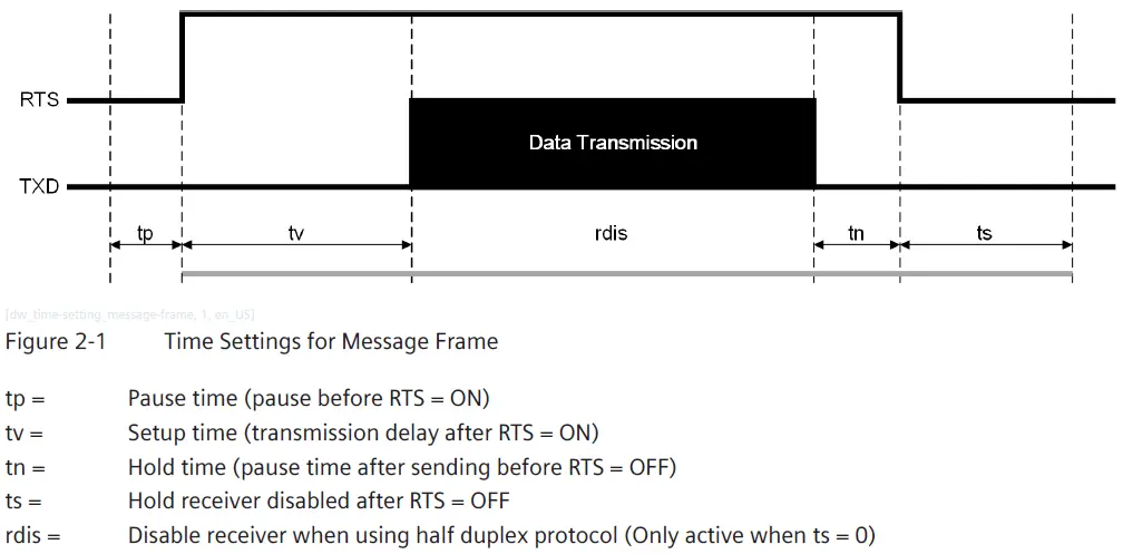
NOTE Only tp or ts must be equal to tdelay for the 7SR45 Argus Relay.
IEC 60870-5-103
Protocol Characteristics
Description
This section describes the IEC 60870-5-103 protocol implementation in the relays. The IEC 60870-5-103 protocol is used for the communication with the Reydisp Evolution software and can also be used for communication with a suitable control system. In the system, the control system or local PC acts as the master and the relay operating as a slave responds to the master commands. The implementation provides:
- Event message
- Time synchronization
- Commands
- Measurand
- Transfer of fault records
The IEC 60870-5-103 protocol can be used in any or all of the relays hardware interfaces (USB, RS485) where it is fitted. The USB interface uses the IEC 60870-5-103 protocol as the standard protocol. The relay can communicate simultaneously on all ports regardless of the protocol used. To enable communication, set the station address of the port being used to a suitable address within the range 0 to 254. You can set the station address using the xxxxx-Stn Addr setting under COMMUNICATION menu.
Application Service Data Unit (ASDU) Type
The following table lists the possible Application Service Data Unit (ASDU) of the Information Number and Function returned for a point.
Table 3-1 Application Service Data Unit Type
| ASDU | Description |
| 1 | Time-tagged message (monitoring direction) |
| 2 | Time-tagged message (relative time; monitoring direction) |
| 4 | Time-tagged measurand with relative time |
| 5 | Identification message |
| 6 | Time synchronization |
| 7 | General-interrogation initialization |
| 9 | Measurands II |
| 20 | General command |
Cause of Transmission
The cause of transmission (COT) column of the Information Number and Function table lists the possible causes of transmission for these frames.
Table 3-2 Cause of Transmission
| Abbreviation | Description |
| SE | Spontaneous event |
| GI | General interrogation |
| Loc | Local operation |
| Abbreviation | Description |
| Rem | Remote operation |
| Ack | Command acknowledge |
| Nak | Negative command acknowledge |
NOTE The events listing a GI cause of transmission can be raised and cleared and other events are raised only.
Point List
Event Function (FUN) & Information (INF) Numbers
The following table lists the data points available via the IEC 60870-5-103 protocol.
NOTE Not all the events are available on all the 7SR45 relay variants.
Table 3-3 Event Function (FUN) & Information (INF) Numbers
| FUN | INF | Description | ASDU | COT |
| 60 | 4 | Remote mode | 1 | SE,GI |
| 20 | Ack, Nak | |||
| 60 | 5 | Out of Service mode | 1 | SE,GI |
| 20 | Ack, Nak | |||
| 60 | 6 | Local mode | 1 | SE,GI |
| 20 | Ack, Nak | |||
| 60 | 7 | Local or Remote mode | 1 | SE,GI |
| 20 | Ack, Nak | |||
| 60 | 13 | Command received | 1 | SE |
| 60 | 128 | Cold start | 1 | SE, GI |
| 60 | 129 | Warm start | 1 | SE, GI |
| 60 | 130 | Restart | 1 | SE, GI |
| 60 | 131 | Expected restart | 1 | SE, GI |
| 60 | 132 | Unexpected restart | 1 | SE, GI |
| 60 | 137 | Clear fault records | 1 | SE |
| 60 | 138 | Clear event records | 1 | SE |
| 60 | 145 | CT input | 1 | SE, GI |
| 60 | 147 | Aux input | 1 | SE, GI |
| 60 | 149 | IRF | 1 | SE, GI |
| 60 | 153 | Battery voltage low | 1 | GI |
| 60 | 158 | Battery voltage critical | 1 | GI |
| 60 | 170 | General alarm 1 | 1 | SE, GI |
| 60 | 171 | General alarm 2 | 1 | SE, GI |
| 60 | 172 | General alarm 3 3 | 1 | SE, GI |
| 60 | 173 | General alarm 4 3 | 1 | SE, GI |
| FUN | INF | Description | ASDU | COT |
| 80 | 1 | Binary output 1 | 1 | SE,GI |
| 20 | Ack, Nak | |||
| 80 | 2 | Binary output 2 | 1 | SE,GI |
| 20 | Ack, Nak | |||
| 80 | 3 | Binary output 3 3 | 1 | SE,GI |
| 20 | Ack, Nak | |||
| 80 | 4 | Binary output 4 3 | 1 | SE,GI |
| 20 | Ack, Nak | |||
| 80 | 66 | Trip pulse output | 1 | SE, GI |
| 90 | 1 | LED 1 | 1 | GI |
| 90 | 2 | LED 2 | 1 | GI |
| 90 | 3 | LED 3 | 1 | GI |
| 90 | 4 | LED 4 | 1 | GI |
| 90 | 5 | LED 5 | 1 | GI |
| 90 | 6 | LED 6 | 1 | GI |
| 90 | 7 | LED 7 | 1 | GI |
| 90 | 8 | LED 8 | 1 | GI |
| 90 | 9 | LED 9 | 1 | GI |
| 160 | 2 | Reset FCB | 5 | SE |
| 160 | 3 | Reset CU | 5 | SE |
| 160 | 4 | Start/Restart | 5 | SE |
| 160 | 5 | Power on | 1 | SE, GI |
| 160 | 19 | LEDs reset (Reset flag and outputs) | 1 | SE |
| 20 | Ack, Nak | |||
| 160 | 22 | Settings changed | 1 | SE |
| 160 | 23 | Settings group 1 select | 1 | SE, GI |
| 20 | Ack, Nak | |||
| 160 | 24 | Settings group 2 select | 1 | SE, GI |
| 20 | Ack, Nak | |||
| 160 | 27 | Binary input 1 | 1 | SE, GI |
| 160 | 28 | Binary input 2 | 1 | SE, GI |
| 160 | 29 | Binary input 3 3 | 1 | SE, GI |
| 160 | 30 | Binary input 4 3 | 1 | SE, GI |
| 160 | 64 | Start/pickup L1 | 2 | SE, GI |
| 160 | 65 | Start/pickup L2 | 2 | SE, GI |
| 160 | 66 | Start/pickup L3 | 2 | SE, GI |
| 160 | 67 | Start/pickup N | 2 | SE, GI |
| 160 | 69 | Trip L1 | 2 | SE, GI |
| 160 | 70 | Trip L2 | 2 | SE, GI |
| 160 | 71 | Trip L3 | 2 | SE, GI |
| 160 | 84 | General start/pickup | 2 | SE, GI |
| 160 | 90 | Trip I> | 2 | SE |
| 160 | 91 | Trip I>> | 2 | SE |
| 160 | 92 | Trip In> | 2 | SE |
| 160 | 93 | Trip In>> | 2 | SE |
| 183 | 0 | Data lost | 1 | SE |
| FUN | INF | Description | ASDU | COT |
| 183 | 10 | 51-1 | 2 | SE, GI |
| 183 | 11 | 50-1 | 2 | SE, GI |
| 183 | 12 | 51N-1 | 2 | SE, GI |
| 183 | 13 | 50N-1 | 2 | SE, GI |
| 183 | 14 | 51G-1 | 2 | SE, GI |
| 183 | 15 | 50G-1 | 2 | SE, GI |
| 183 | 17 | 50-2 | 2 | SE, GI |
| 183 | 19 | 50N-2 | 2 | SE, GI |
| 183 | 21 | 50G-2 | 2 | SE, GI |
| 183 | 35 | 49 Alarm | 2 | SE, GI |
| 183 | 36 | 49 Trip | 2 | SE, GI |
| 183 | 96 | 81HBL2 | 1 | SE, GI |
| 183 | 225 | 50LC | 2 | SE, GI |
| 183 | 239 | In fault current | 4 | SE |
| 183 | 240 | Ia fault current | 4 | SE |
| 183 | 241 | Ib fault current | 4 | SE |
| 183 | 242 | Ic fault current | 4 | SE |
| 183 | 243 | Ig fault current | 4 | SE |
| 185 | 107 | Reclose inhibit | 2 | SE, GI |
| 185 | 123 | Reset thermal level | 1 | SE |
| 20 | Ack, Nak | |||
| 255 | 0 | Time synchronization | 6 | Time synchronization |
| 255 | 0 | GI initiation | 7 | GI |
| 255 | 0 | End of GI | 8 | End of GI |
NOTE For the list of events raised, refer to A.2 Events Raised.
Measurands
The following measurands and INF numbers apply to the 7SR45 Argus Relay.
Table 3-4 Measurands
| FUN | INF | Description | ASDU | COT |
| 183 | 148 | Measurand IL1, 2, 3 — IL1 (2.4x) IL2 (2.4x) IL3 (2.4x) | 9 | Cyclic – refresh rate 5 s |
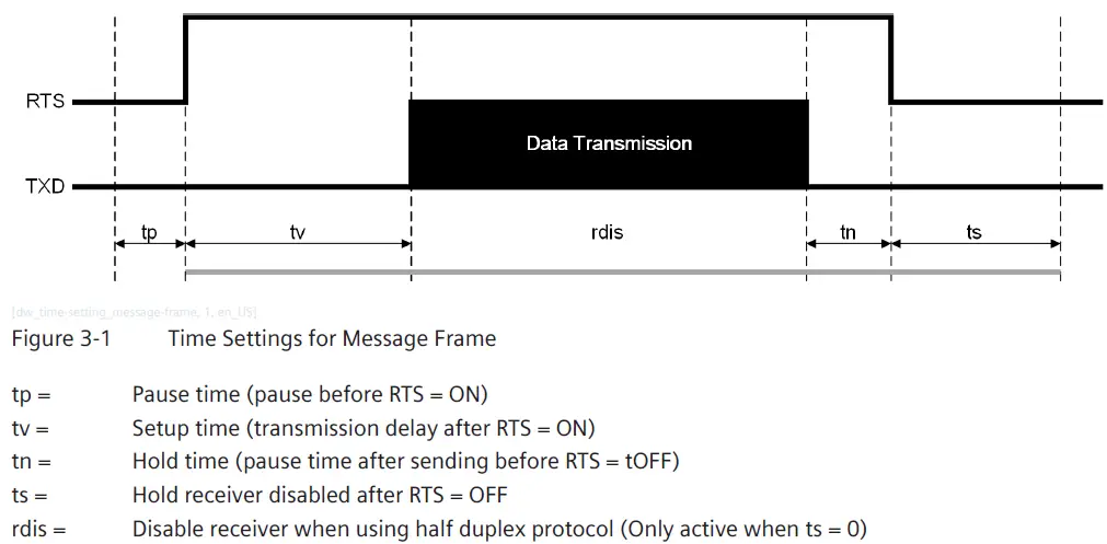
NOTE In the IEC 60870-5-103, message frames are separated with a silent interval of at least 3.5 character times and the time interval is also called t3.5. The IEC 60870-5-103 master provides the t3.5 delay for responding to another query.
The following silent interval time equation is implemented in the 7SR45 Argus Relay:
t delay required = 11 bits ⋅ 3.5/b
Where
b = baud rate in bit/s
tdelay for 7SR45 = tdelay required + 10 ms tolerance
Troubleshooting
- Relays do not communicate in a multi-drop network
- Siemens recommends proceeding as follows:
- Check that all relays are powered up with auxiliary power supply.
- Check the polarity of rear communication terminal and connection.
- Check that all relays have unique addresses.
- Check if RS485 terminating resistor is required and in circuit.
- Siemens recommends proceeding as follows:
- Cannot communicate with the relay through Reydisp Evolution
- Siemens recommends proceeding as follows:
- Check the communication cable is connected properly.
- Check that the USB driver is installed correctly.
- In Reydisp Evolution, verify that Do NOT Check Communications Connection is selected in the Advanced properties.
- In Reydisp Evolution, check that the relay address is set as 1 in the Relay menu.
- Ensure that IEC 60870-5-103 is specified for the connected port (COM1 or COM2).
- Siemens recommends proceeding as follows:
Appendix
Operating Mode
The 7SR45 Argus relay has 4 operating modes:
- Local
- Remote
- Local or Remote
- Out of service
The following table identifies the operation of the function in each mode. You can select the modes in the following methods:
SETTING MODE > SYSTEM CONFIG > Operating Mode, a binary input, or command through rear/front communication protocols.
Table A-1 Operating Mode
| Operation Control | Remote Mode | Local Mode | Out of Service Mode |
| USB/Rear ports set to REMOTE4 | Enabled | Disabled | Disabled |
| USB/Rear ports set to LOCAL4 | Disabled | Enabled | Disabled |
| USB/Rear ports set to LOCAL or REMOTE4 | Enabled | Enabled | Disabled |
| Binary inputs | Enabled | Enabled | Enabled |
| Binary outputs | Enabled | Enabled | Disabled |
| Reporting | |||
| Spontaneous | |||
| IEC60870-5-103 | Enabled | Enabled | Disabled |
| General interrogation | |||
| IEC60870-5-103 | Enabled | Enabled | Disabled |
| MODBUS-RTU | Enabled | Enabled | Enabled |
| Change of settings | |||
| USB/Rear ports set to REMOTE 4 | Enabled | Disabled | Enabled |
| USB/Rear ports set to LOCAL 4 | Disabled | Enabled | Enabled |
| USB/Rear ports set to LOCAL or REMOTE4 | Enabled | Enabled | Enabled |
| Fascia | Enabled | Enabled | Enabled |
| Historical Information | |||
| Event records | Enabled | Enabled | Enabled |
| Fault information | Enabled | Enabled | Enabled |
| Setting information | Enabled | Enabled | Enabled |
The communication port modes can be selected at: SETTING MODE > COMMUNICATION.
Events Raised
- Cold Start Raised
The cold start event is raised for any setting conditions in the absence of main battery. - Warm Start Raised
The warm start event is raised when the device goes from the sleep mode to wake-up mode. - Restart
The restart event is raised whenever any of the following event occurs:- Expected restart
- Unexpected restart
- Cold start
- Expected Restart
The expected restart event is raised when an expected restart occurs. - Unexpected Restart
The unexpected restart event is raised when an unexpected restart occurs. Both the expected and unexpected restart cannot occur at the same time. - Power on
The power on event is raised when the battery is discharged completely.
Revision History
Software Revision History:
| 2020/09 | 2438H80001R2f-1b | Software maintenance |
| 2020/08 | 2438H80001R2f-1a | • Protection function 51-1 setting range change to 0.1 ⋅ Irated to 2.0 ⋅ Irated • User-Programmable LED feature added |
| 2020/05 | 2438H80001R2e-1b | Software maintenance |
| 2019/12 | 2438H80001R2e-1a | Thermal overload protection function (49) added |
| 2019/05 | 2438H80001R2c-1b | Software maintenance to suit customer requirements |
| 2018/11 | 2438H80001R2c-1a | Supervision function (81HBL2) added |
| 2018/06 | 2438H80001R1f-1a | Third Release |
| 2018/06 | 2438H80001R2b-1b | Third Release |
| 2018/04 | 2438H80001R2a-1a | Second Release |
| 2017/08 | 2438H80001R1e-1a | Software maintenance to suit customer requirements |
| 2017/01 | 2438H80001R1d-1a | • Protection function 50, 50N, 50G setting range change to 0.2 ⋅ Irated to 20 ⋅ Irated in step of 0.1 ⋅ Irated • Protection function 50, 50N, 50G reset ratio changed to 90 % for setting below 1 ⋅ Irated and 94 % for setting above 1 ⋅ Irated |
| 2016/10 | 2438H80001R1c-1a | Software maintenance to suit customer requirements |
| 2016/09 | 2438H80001R1b-1a | • Faster response times on 1 phase (t + 100 ms max) in 0.2 to 0.3 ranges. • IRF functionality. |
| 2015/08 | 2438H80001R1a-1a | First Release |
Hardware Revision History:
| 2021/11 | 7SR450/HH | V1 obsolete and UL certified |
| 2020/09 | 7SR450/GG | Fourth Release (with conformal coating PCBA) |
| 2018/06 | 7SR450/FF | Third Release (with reduced front cover and housing height) |
| 2018/04 | 7SR450/EE | Second Release (with Aux. Power supply, remote flag and local flag, RS 485, additional AC/DC BIs and BOs) |
| 2017/02 | 7SR450/DD | Hardware maintenance |
| 2016/09 | 7SR450/CC | Circuit changes to improve signal conditioning |
| 2015/08 | 7SR450/BB | First Release |
Software and Hardware Versions Compatibility
Table A-2 Software Compatibility for MLFB Variants 7SR450[1/3]-[1/2]GA10-1AA0
| Software Version | Hardware Version | |||||
| 7SR4501/BB | 7SR4501/CC | 7SR4501/DD | 7SR4501/EE | 7SR450[1/3]/FF | 7SR450[1/3]/GG | |
| 2438H80001R1a-1a | ■ | |||||
| 2438H80001R1b-1a | ■ | ■ | ■ | ■ | ||
| 2438H80001R1c-1a | ■ | ■ | ■ | ■ | ||
| 2438H80001R1d-1a | ■ | ■ | ■ | ■ | ||
| 2438H80001R1e-1a | ■ | ■ | ■ | ■ | ||
| 2438H80001R1f-1a | ■ | ■ | ■ | ■ | ||
Table A-3 Software Compatibility for MLFB Variants: 7SR450[1/2/3/4]-[1/2][H/J][A/B]20-1A[A/B]0, 7SR450[1/2/3/4]-[1/2][H/J][A/B]20-1A[A/B]0
| Software Version | Hardware Version | |||
| 7SR450[1/2]/EE | 7SR450[1/2/3/4]/FF | 7SR450[1/2/3/4]/GG | 7SR450[1/2/3/4]/HH | |
| 2438H80001R2a-1a | ■ | |||
| 2438H80001R2b-1b | ■ | ■ | ||
| 2438H80001R2c-1a | ■ | ■ | ||
| 2438H80001R2c-1b | ■ | ■ | ||
| 2438H80001R2e-1a | ■ | ■ | ||
| 2438H80001R2e-1b | ■ | ■ | ||
| 2438H80001R2f-1a | ■ | ■ | ||
| 2438H80001R2f-1b | ■ | ■ | ■ | ■ |
NOTE The firmware for the MLFB 7SR450[1/3]-[1/2]GA10-1AA0 is migrated from the R1x series to R2x series from the HH hardware. The firmware series are not interchangeable and Siemens recommends to follow the guidelines mentioned in the Table A-2 and Table A-3.
Glossary
- Baud rate
Data transmission speed. - Bit
The smallest measure of computer data. - Bits per second (Bit/s)
Measurement of data transmission speed. - Data bits
Several bits containing the data. Sent after the start bit. - Parity
Method of error checking by counting the value of the bits in a sequence and adding a parity bit to make the outcome. For example, even. - Parity bit
Bit used for implementing parity checking. Sent after the data bits. - RS485
Serial Communications Standard. Electronic Industries Association Recommended Standard Number 485. - Start bit
Bit (logical 0) sent to signify the start of a byte during data transmission. - Stop bit
Bit (logical 1) sent to signify the end. - USB
Universal Serial Bus standard for the transfer of data.
Disclaimer of Liability
Subject to changes and errors. The information given in this document only contains general descriptions and/or performance features that may not always specifically reflect those described, or which may undergo modification in the course of further development of the products. The requested performance features are binding only when they are expressly agreed upon in the concluded contract.
Document version: C53000-L7040-C101-3.0
Edition: 11.2021
Version of the product described: V03.00
Copyright © Siemens 2021. All rights reserved.
The disclosure, duplication, distribution and editing of this document, or utilization and communication of the content are not permitted unless authorized in writing. All rights, including rights created by patent grant or registration of a utility model or a design, are reserved.


