DAUDIN AS300 Series Remote I-O Module System User Manual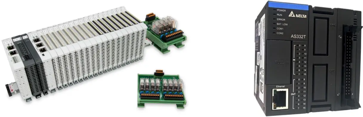
Remote I/O Module System Configuration List
| Part No | Specification | Description |
| GFMS-RM01S | Master Modbus RTU, 1 Port | Main Controller |
| GFDI-RM01N | Digital Input 16 Channel | Digital Input |
| GFDO-RM01N | Digital Output 16 Channel / 0.5A | Digital Output |
| GFPS-0202 | Power 24V / 48W | Power Supply |
| GFPS-0303 | Power 5V / 20W | Power Supply |
| 0170-0101 | 8 pin RJ45 female connector/RS-485 Interface | Interface Module |
Product Description
- The interface module is used externally to convert AS300 RS485’s communication port (Modbus RTU) to a RJ45 connector
- The main controller is in charge of the management and dynamic configuration of I/O parameters and so on.
- The power module and interface module are standard for remote I/Os and users can choose the model or brand they prefer.
AS300 Connection Setup
This chapter explains how to use the ISPSoft program to connect AS300 with . For detailed information, please refer to the ISPSoft User Manual
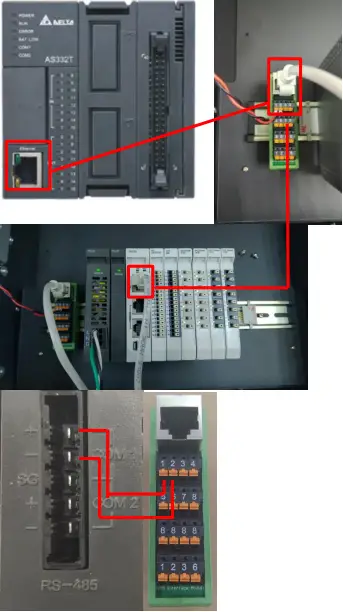
AS300 Hardware Connection
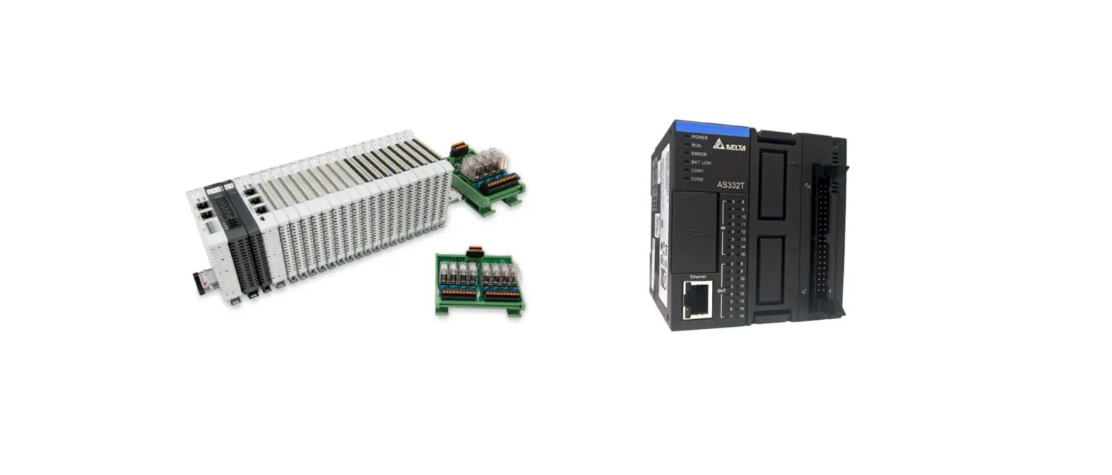
- The connection port is at the bottom of the machine. Using AS332T-A with COM1 (RS485 pin) for demonstration, connect COM1(RS485 +/-) to the interface module (1/2) to convert it into a RJ45 connector, which will be onnected to the main controller

AS300 Connection Setup
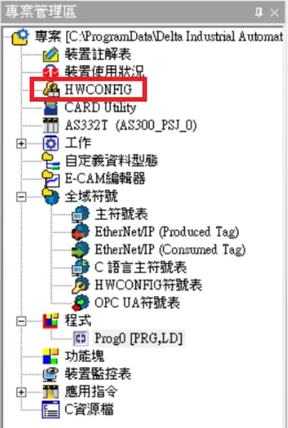
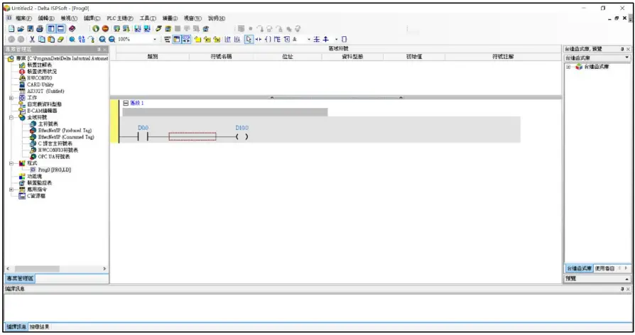
- Launch ISPSoft, create a new file and double-click “HWCONFIG” on the project management section on the left to enter the configuration page

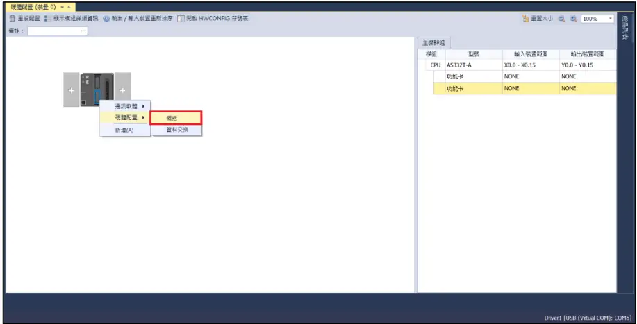
- Right click on the PLC icon and select “Summary” under “Hardware Configuration”

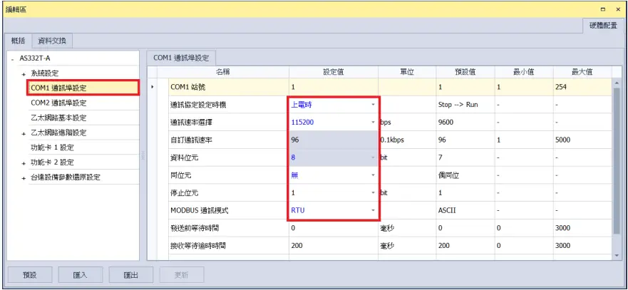
- For this demonstration, click on “COM1 Communication Port Settings” and set COM1’s communication settings to RTU mode, 115200bps, 8 data bits, None parity and 1 stop bits (115200, 8, N, 1). Programming example:

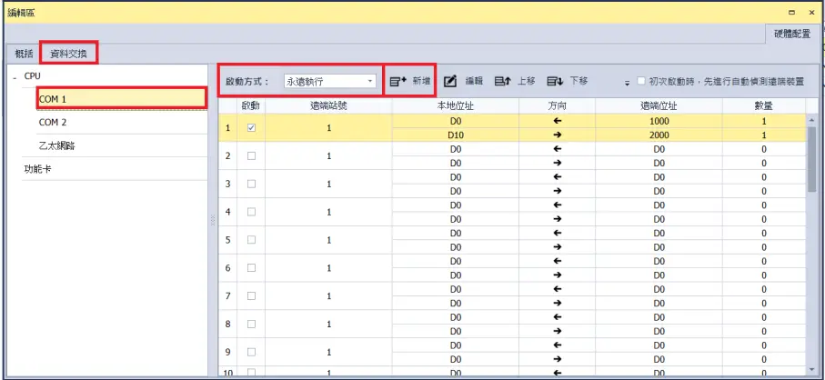
- Click on “Data Exchange” on the left to switch to the Data Exchange page and select the desired COM PORT (COM1 in this case). Make sure to select otherwise the data communication will not be initiated. Select “Add” or modify existing fields to set up the communication

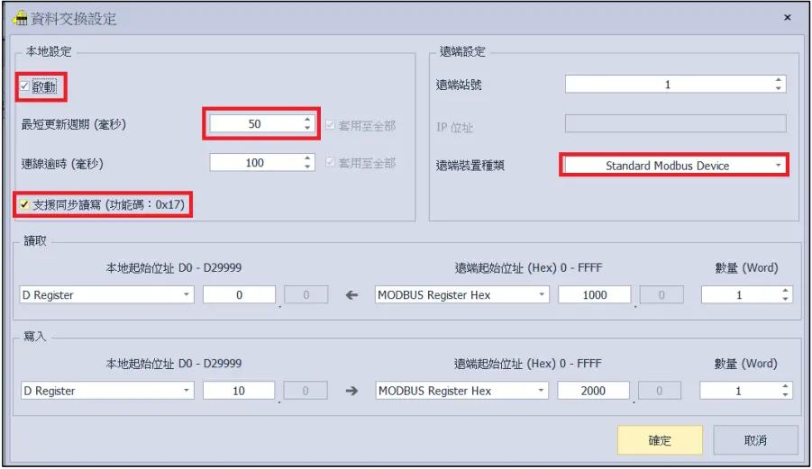
- “Data Exchange Settings” image and details:

- To use that communication, make sure to check “Initiate”
- When there are too many addresses to read and write, increase the “Minimum Refresh Cycle”.
- control module can accept 0x17 function code while reducing the communication time by one writing and one reading
- For “Remote Device Type”, select “Standard Modbus Device”
※ ’s first GFDI-RM01N has the register address at 1000(HEX)
※ ’s first GFDO-RM01N has the register address at 2000(HEX)
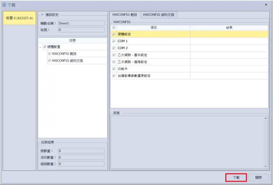
- Once the setup is complete, click on “Download” for the setting to be incorporated in PLC

- Once the register for data storage is set up following the instructions above in the ISPSoft program, it is ready to use