IDEC SX5E Unmanaged Switches Instruction Manual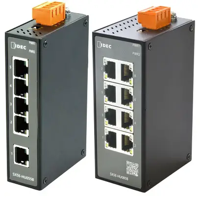
Product Overview
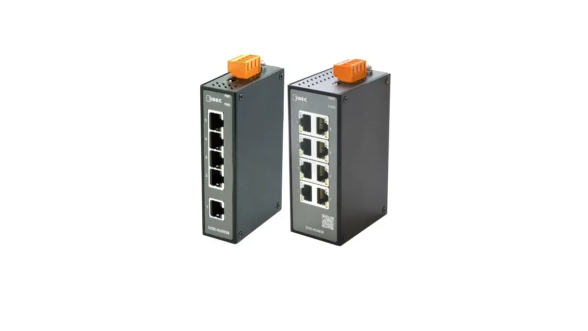
SX5E is an entry-level industrial Ethernet switch designed for the factory automation industry. SX5E with QoS capabilities and an IP30-protected metal enclosure, efficiently allocates network bandwidth, makes rational use of network resources, and ensures fast and reliable data transmission in harsh industrial environments. Broadcast storm prevention function (BPS) and Quality of Service (QoS) can be turned on or off by setting DIP switches. This series support DIN-Rail installation. The configuration is shown in the following table:
Table 1 SX5E Models
| Model | SX5E-HU085B |
| Ports | 8T |
| 8T=eight 10/100Base-T(X) ports | |
| PS1-PS2: power input | LV-LV=24VAC/DC (18-30VAC, 50/60Hz; 12-48VDC), redundant power input) |
| Terminal Block | 4-Pin 5.08mm-Spacing Plug-in Terminal Block |
| Rated Power Consumption | 4.1W |
| Housing | Metal, fanless |
| Protection Class | IP30 |
| Installation | DIN-Rail Mounting |
| Dimensions (WxHxD) | 45.6mm×114.5mm×68mm (excluding connectors, DIN rail mounting kit) |
| Weight | < 0.25Kg |
| Applicable Environmental | Indoor |
| Ambient Temperature | -40ºC – +75ºC |
| Storage Temperature | -40ºC – +85ºC |
| Ambient Relative Humidity | 5% – 95% (no condensing) |
| Altitude | 2000m |
| MTBF | 1161219h |
| Warranty | Five years |
![]() Note:
Note:
- We reserves the right to change the product information in this table without notice. To obtain the latest information, please visit our web page.
Structure and Interface
![]() Caution:
Caution:
- To keep the ports clean and free of dust and dirt, and to ensure the performance of the product, we recommend the use of a connector cover for the RJ45 port (optional accessory).
Front Panel
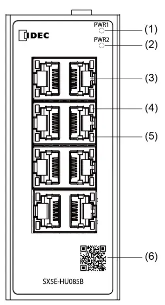
Figure 1 Front Panel
- Power 1 LED
- Power 2 LED
- 10/100Base-T(X) Ethernet port
- 10/100Base-T(X) Ethernet port connection status LED (green)
- 10/100Base-T(X) Ethernet port speed LED (yellow)
- QR Code (URL to download the Instruction Sheet)
Top Panel
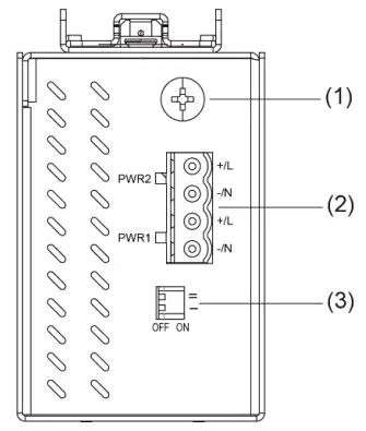
Figure 2 Top Panel
- Grounding screw
- Power terminal block
- DIP switches
Mounting
Dimension Drawing
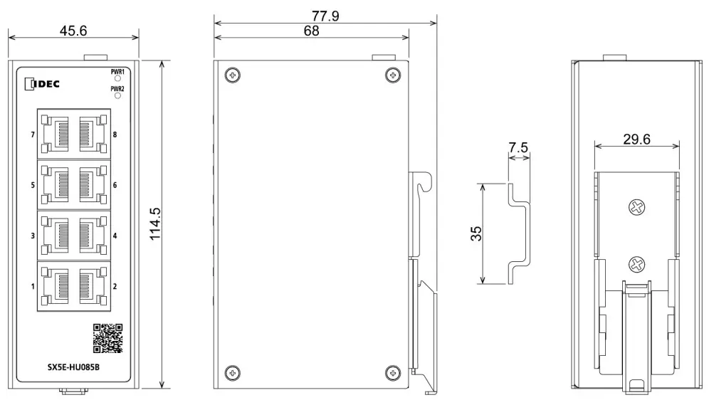
Figure 3 SX5E Dimensions for DIN-Rail Mounting (unit: mm)
![]() Caution:
Caution:
- As part of the heat dissipation system, the switch housing becomes hot during operation. Please use caution when coming in contact and avoid covering the switch housing when the switch is running.
- The figures in this manual are only for reference.
Mounting
The device supports DIN-rail mounting. Make sure that the following requirements are met before installation.
![]() Note:
Note:
- Devices are to be installed in an ATEX /IECEx Certified IP54 enclosure and accessible only by the use of a tool.
- Devices are for use in an area of not more than pollution degree 2 in accordance with IEC 60664-1.
- Customer shall insure device working in the right ambient temperature, -40 ~+75℃ for SX5E series.
- No direct sunlight, distant from heat source and areas with strong electromagnetic interference.
- Provide sufficient space for heat dissipation.
DIN-Rail Mounting
DIN-rail mounting can be done by one of the following methods.
Step 1: Hook the DIN rail mounting kit to the top of the DIN rail.
Step 2: Press the bottom of the device so that the DIN rail fits into the DIN rail mounting kit. Make sure that the device is firmly attached to the DIN rail.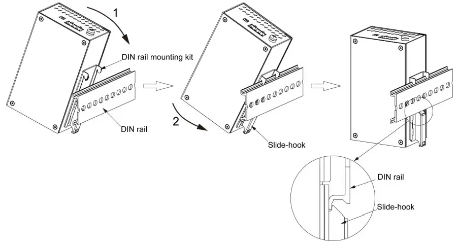
Figure 4 DIN-Rail Mounting 2
DIN-Rail Dismounting
Step 1: Insert the screwdriver into the slide-hook hole of the DIN rail mounting kit.
Step 2: Pull the bottom part of the main body toward you while sliding the Slide-hook downward.
Step 3: Dismount the hook of the DIN rail mounting kit from the DIN rail.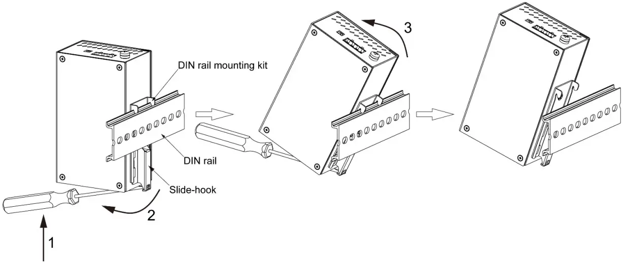
Figure 5 DIN-Rail Dismounting
Connection
10/100Base-T(X) Ethernet Port
10/100Base-T(X) Ethernet port is equipped with RJ45 connector. The port is self-adaptive. It can automatically configure itself to work in 10M or 100M state, full or half duplex mode. The port can also adapt to MDI or MDIX connection automatically. You can connect the port to a terminal or network device with a straight-through or cross-over cable.
- Pin Definition

Figure 6 RJ45 Port
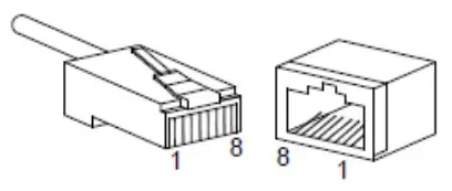
Table 2 Pin Definitions of 10/100Base-T(X) RJ45 Port
| Pin | MDI-X Signal | MDI Signal |
| 1 | Receive Data+ (RD+) | Transmit Data+ (TD+) |
| 2 | Receive Data- (RD-) | Transmit Data- (TD-) |
| 3 | Transmit Data+ (TD+) | Receive Data+ (RD+) |
| 6 | Transmit Data- (TD-) | Receive Data- (RD-) |
| 4, 5, 7, 8 | Unused | Unused |
![]() Note:
Note:
“+” and “-” indicate level polarities
- Wiring Sequence

Figure 7 Connection Using Straight-through/Cross-over Cable
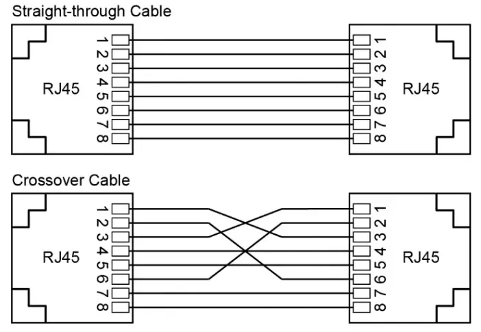
![]() Note:
Note:
The color of the cable for RJ45 connector meets the 568B standard: 1-orange and white, 2-orange, 3-green and white, 4-blue, 5-blue and white, 6-green, 7-brown and white, and 8-brown.
Grounding
Grounding protects the device from lightning and interference. Therefore, you must ground the device properly. ou need to ground the device before it is powered on and disconnect the grounding cable after the device i powered off.
There is a grounding screw (see Figure 2) on the top panel of the device. The screw is for chassis grounding. After crimping one end of the grounding cable to a cold pressed terminal, secure the end of the grounding cable to the grounding screw and firmly connect the other end to ground.
![]() Note:
Note:
Cross-sectional area of the chassis grounding cable > 2.5mm2
Power Terminal Block
There is a power terminal block on the top panel of the device. You need to connect the power wires to the terminal block to provide power for the device. The device supports redundant power supply with 4-pin 5.08mmspacing plug-in terminal block. When one power input is faulty, the device can continue operating properly, thereby ensure network reliability.
![]() Note:
Note:
Wiring must use lead sizes that are appropriate for the applied voltage and current. Terminal screws must be tightened with the prescribed tightening torque. Do not add any intermediate connecting parts other than ferrules.
- 4-Pin 5.08mm Plug-in Terminal Block

Figure 8 4-Pin 5.08mm Plug-in Terminal Block (socket)
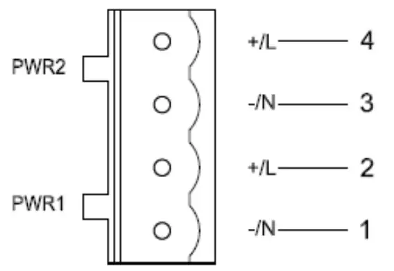
Table 3 Pin Definitions of 4-Pin 5.08mm Plug-in Terminal Block
| Pin Number | DC Wiring Definition | AC Wiring Definition |
| 1 | PWR1: – | PWR1: N |
| 2 | PWR1: + | PWR1: L |
| 3 | PWR2: – | PWR2: N |
| 4 | PWR2: + | PWR2: L |
Wiring and Mounting
Step 1: Ground the device properly according to section 4.2.
Step 2: Remove the power terminal block from the device.
Step 3: Insert the power wires into the power terminal block according to Table 3 and secure the wires.
Step 4: Insert the terminal block with the connected wires into the terminal block socket on the device.
Step 5: Connect one end of the power cable to an external power supply system (with the allowed power range). If the power LED on the front panel of the switch turns on, the power supply is connected properly.
Wiring and mounting should meet following specifications.
Table 4 Wiring and Mounting Specifications
| Terminal Type | Required Torque | Wire Range (AWG) |
| Terminal Block Plug | 0.5Nm | 12-24 |
![]() Caution:
Caution:
- Provision shall be made to prevent the rated voltage from being exceeded by transient disturbances of more than 140% of the rated voltage.
- Use a power supply of the rated value. Use of a wrong power supply may cause fire hazard.
- To comply with UL restrictions, this equipment must be powered from a source compliant with SELV.
![]() Warning:
Warning:
- Turn off power to the device before installation, removal, wiring, maintenance, and inspection of the device. Failure to turn power off may cause damage, electrical shocks or fire hazard.
DIP Switches
There are two DIP switches on the top panel of the device, each switch has ON and OFF states, and the default state is OFF. DIP switchesⅠenable and disable broadcast storm protection function, DIP switchesⅡenable and disable QoS function.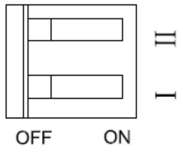
Figure 9 DIP Switches
Optional Function
Broadcast Storm Protection (BSP) function
If a large amount of broadcast packets are sent (broadcast storm), a communication error may occur or a network trouble such as the performance degradation of the entire network may occur. When you enable the Broadcast Storm Protection (BSP) function, it is possible to protect the network from such a network trouble.
Quality of Service (QoS) function
When you enable the QoS function, this product monitors the traffic to process, and preferentially processes communications via EtherNet/IPTM. This allows EtherNet/IPTM communications to be performed stably even if a large amount of traffic, for example, with video images and still images occurs.
Internet Group Management Protocol (IGMP) Snooping function
When you enable the IGMP snooping function, the product will send multicast packets only to the port where the multicast packets are required, and control the transmission of packets to the other ports. This prevents unnecessary traffic from occurring.
How to use these functions
To enable/disable each of these functions, set its corresponding DIP switch to ON/OFF..
| DIP1 | DIP2 | Function | |
| State 1 | OFF | OFF | Default configurations, disable BSP and QoS |
| State 2 | ON | OFF | Enable BSP |
| State 3 | OFF | ON | Enable QoS. |
| State 4 | ON | ON | Enable BSP and QoS |
LEDs
Table 5 LEDs
| LED | State | Description |
| Power 1 LED | On | The power 1 is connected and operates properly. |
| Off | The power 1 is not connected or operates abnormally. | |
| Power 2 LED | On | The power 2 is connected and operates properly. |
| Off | The power 2 is not connected or operates abnormally. | |
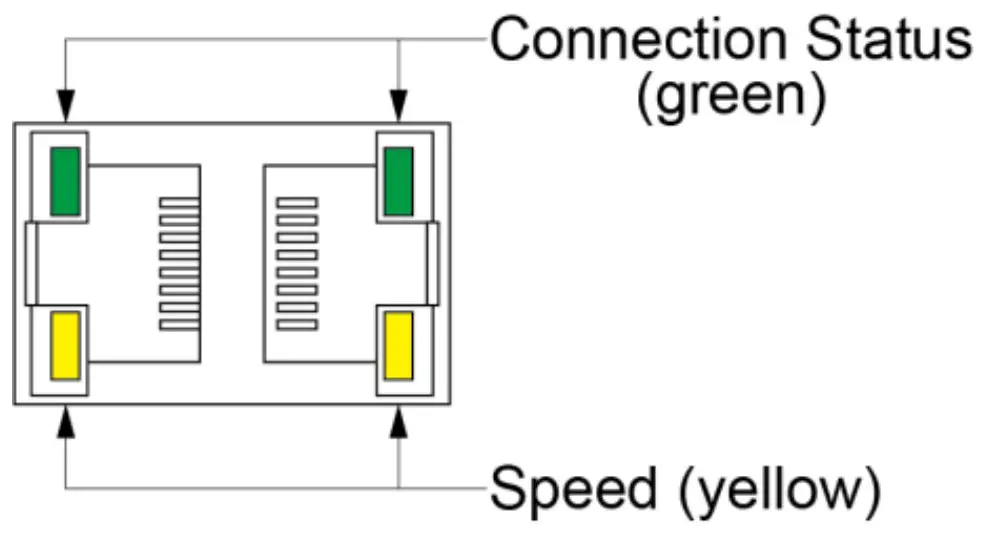 | ||
| 10/100Base-T(X) Ethernet port speed LED (yellow) | On | 100M working state (100Base-TX) |
| Off | 10M working state or no connection | |
| 10/100Base-T(X) Ethernet port connection status LED (green) | On | Effective port connection |
| Blinking | Ongoing network activities | |
| Off | No effective port connection | |
Certificates
| Certificates Approvals | |
| EMC | CE,FCC 47CFR Part2 and part15 Class A |
| Safety | UL61010 |
8 Option
| SX9Z-PMTD04PN02 | Power Supply Terminal Block (2 pieces) |
| SX9Z-CAP2PN02 | Connector cover for RJ45 port (2 pieces) |
| SX9Z-1A01 | Direct mounting bracket (1 pieces) |
Direct mounting bracket
Step 1: Remove the DIN rail mounting kit after removing fixation screws.
Step 2: Fix the direct mounting bracket in two places using the supplied screws in the direction shown. (Tightening torque: 0.39-0.41 Nm).
Figure 10 Direct mounting bracket
Disclaimer: IDEC Corporation tries to keep the content of this manual as accurate and as updated as possible. This document is not guaranteed to be error-free, and we reserve the right to amend it without notice to users.
All rights reserved.
All rights related to this manual are reserved by IDEC Corporation. No part of this document may be reproduced, reprinted, sold, transferred, or leased without the prior written permission of IDEC Corporation.
Notice for Safety Operation
The product performs reliably as long as it is used according to the guidance. Artificial damage or destruction of the device should be avoided. Before using the device, read this notice carefully for personal and equipment safety. Please keep the manual for further reference. If the device used not according to the specified way by IDEC, the protection provided by the device maybe diminished. And IDEC is not liable to any personal or equipment damage caused by violation of this notice.
- Users must add backup or failsafe provisions to control systems use SX5E in applications where heavy damage or personal injury may be caused if SX5E should fail.
- Ensure the area where the device is used is clean and dry. Keep the ambient relative humidity within the range from 5% to 95% (non-condensing). This equipment may only be used indoors.
- Do not place the device in an environment with high magnetic field, strong shock, or high temperature. Keep the working and storage temperatures within the allowed range.
- Install and place the device securely and firmly.
- Please keep the device clean; if necessary, wipe it with a soft cotton cloth.
- Do not place any irrelevant materials on the device or cables. Ensure adequate heat dissipation and tidy cable layout without being entangled or knotted.
- Wear antistatic gloves or take other protective measures when operating the device.
- Avoid any exposed metal wires because they may be oxidized or electrified.
- Install the device in accordance with related national and local regulations.
- Before power-on, make sure the power supply is within the allowed range of the device. High voltage may damage the device.
- Connect the power connector and Ethernet cable connector firmly.
- Do not plug in or out the power supply with wet hands. When the device is powered on, do not touch the device or any parts with wet hands.
- Before operating a device connected to a power cable, remove all jewelry (such as rings, bracelets, watches, and necklaces) or any other metal objects, because they may cause electric shock, burns, or welding.
- Do not operate the device or connect or disconnect cables during an electrical storm.
- Use compatible connectors and cables. If you are not sure, contact our sales or technical support personnel for confirmation.
- Do not disassemble the device by yourself. When an anomaly occurs, contact our sales or technical support personnel.
- If any part is lost, contact our sales or technical support personnel to purchase a replacement. Do not purchase parts from other channels.
- Dispose of the device in accordance with relevant national regulation, preventing environmental pollution.
In the following cases, please immediately shut down your power supply and contact your IDEC representative:
- Water gets into the equipment.
- Equipment damage or shell damage.
- Equipment operation or performance has abnormally changed.
- The equipment emits odor, smoke or abnormal noise.
Note: The security of any system merged with this device is the responsibility of the assembler.
NOTE: This equipment has been tested and found to comply with the limits for a Class A digital device, pursuant to part 15 of the FCC Rules. These limits are designed to provide reasonable protection against harmful interference when the equipment is operated in a commercial environment. This equipment generates, uses, and can radiate radio frequency energy and, if not installed and used in accordance with the instruction manual, may cause harmful interference to radio communications. Operation of this equipment in a residential area is likely to cause harmful interference in which case the user will be required to correct the interference at his own expense.
Supplier’s Declaration of Conformity 47 CFR § 2.1077 Compliance Information
Unique Identifier: SX5E-HU085B
Responsible Party – U.S. Contact Information
IDEC Corporation
1175 Elko Drive, Sunnyvale, CA 94089-2209, USA
Tel: +1-408-747-0550 [email protected]
FCC Compliance Statement
This device complies with Part 15 of the FCC Rules. Operation is subject to the following two conditions: (1) This device may not cause harmful interference, and (2) this device must accept any interference received, including interference that may cause undesired operation.
![]()


