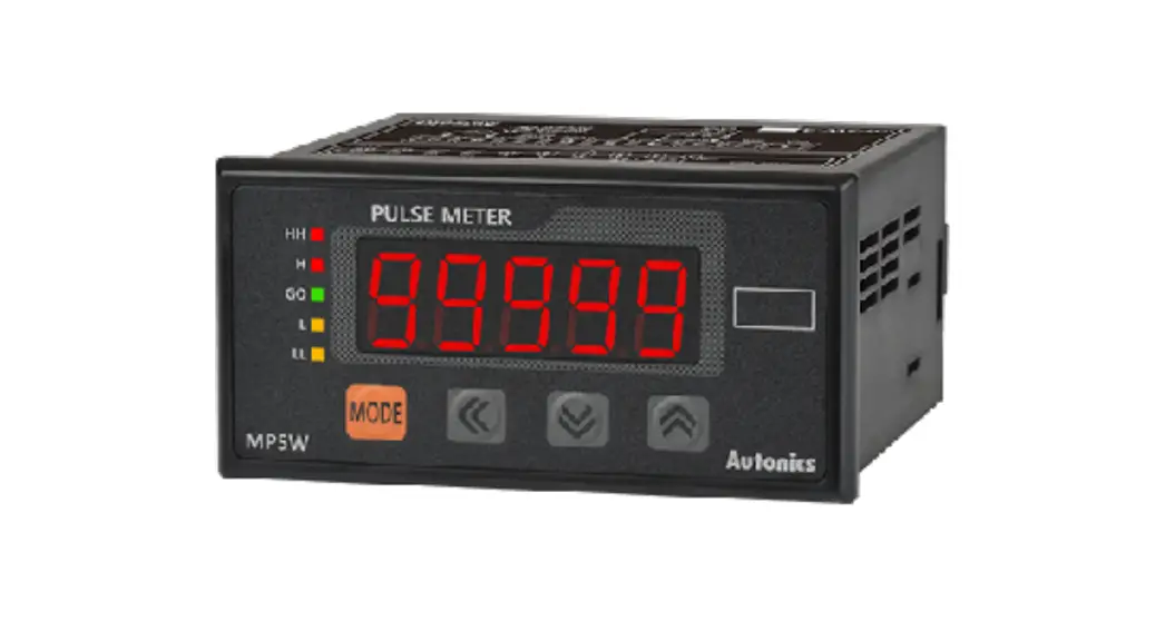
![]() MP5S / MP5Y / MP5W Series
MP5S / MP5Y / MP5W Series
PRODUCT MANUAL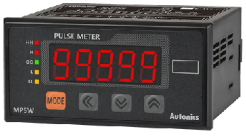
MP5S Series Multi Pulse Meters
For your safety, read and follow the considerations written in the instruction manual, other manuals and Autonics website.
The specifications, dimensions, etc. are subject to change without notice for product improvement. Some models may be discontinued without notice.
Features
- 16 operation modes
– Frequency / revolutions / speed, passing speed, cycle, passing time, time interval
– Time differential, absolute ratio, error ratio, density, error, length measurement 1 / 2, interval
– Accumulation, addition / subtraction (individual input), addition / subtraction (phase difference input) - Various output models
– Relay triple / quintuple output, NPN / PNP open collector quintuple output
– BCD Dynamic output, PV transmission output (current output)
– RS485 communication output (Modbus RTU) - Various function
– Prescale, delay monitoring, hysteresis, auto-zero, parameter lock, data bank (MP5W only) - Display range: -19999 to 99999
- Various display units
![]()
Safety Considerations
- Observe all ‘Safety Considerations’ for safe and proper operation to avoid hazards.
 symbol indicates caution due to special circumstances in which hazards may occur.
![]() Warning Failure to follow instructions may result in serious injury or death.
Warning Failure to follow instructions may result in serious injury or death.
- Fail-safe device must be installed when using the unit with machinery that may cause serious injury or substantial economic loss. (e.g. nuclear power control, medical equipment, ships, vehicles, railways, aircraft, combustion apparatus, safety equipment, crime / disaster prevention devices, etc.)
Failure to follow this instruction may result in personal injury, economic loss or fire. - Do not use the unit in the place where flammable / explosive / corrosive gas, high humidity, direct sunlight, radiant heat, vibration, impact, or salinity may be present.
Failure to follow this instruction may result in explosion or fire. - Install on a device panel to use.
Failure to follow this instruction may result in fire or electric shock. - Do not connect, repair, or inspect the unit while connected to a power source.
Failure to follow this instruction may result in fire or electric shock. - Check ‘Connections’ before wiring.
Failure to follow this instruction may result in fire. - Do not disassemble or modify the unit.
Failure to follow this instruction may result in fire or electric shock.
![]() Caution Failure to follow instructions may result in injury or product damage.
Caution Failure to follow instructions may result in injury or product damage.
- When connecting the power / measurement input and relay output, use AWG 24 (0.20 mm2) to AWG 15 (1.65 mm2) cable and tighten the terminal screw with a tightening torque of 0.98 to 1.18 N m.
Use the wiring suitable for the load current capacity.
Failure to follow this instruction may result in fire or malfunction due to contact failure. - Use the unit within the rated specifications.
Failure to follow this instruction may result in fire or product damage. - Use dry cloth to clean the unit, and do not use water or organic solvent.
Failure to follow this instruction may result in fire or electric shock. - Keep the product away from metal chip, dust, and wire residue which from flowing into the unit.
Failure to follow this instruction may result in fire or product damage.
Cautions during Use
- Follow instructions in ‘Cautions during Use’.
Otherwise, it may cause unexpected accidents. - Power supply should be insulated and limited voltage / current or Class 2, SELV power supply device.
- Install a power switch or circuit breaker in the easily accessible place for supplying or disconnecting the power.
- Use twisted pair wire for communication line.
- Keep away from high voltage lines or power lines to prevent inductive noise.
In case installing power line and input signal line closely, use line filter or aristocrat at power line and shielded wire at input signal line. Do not use near the equipment which generates strong magnetic force or high frequency noise. - This unit may be used in the following environments.
– Indoors (in the environment condition rated in ‘Specifications’)
– Altitude max. 2,000 m
– Pollution degree 2
– Installation category II
Ordering Information
This is only for reference, the actual product does not support all combinations.
For selecting the specified model, follow the Autonics website. ❶ Size
S: DIN W 48 × H 48 mm
Y: DIN W 72 × H 36 mm
W: DIN W 96 × H 48 mm
❷ Power supply
2: 24 VAC ∼ 50 / 60 Hz, 24 – 48 VDC ![]()
4: 100 – 240 VAC ∼ 50 / 60 Hz
❸ Output
| Output | Main (comparative value) output | Sub (display value) output | |
| MPSS | N | Indicator | – |
| MP5Y | N | Indicator | – |
| 1 | NPN open collector quintuple | – | |
| 2 | PNP open collector quintuple | – | |
| 3 | Indicator | BCD Dynamic | |
| 4 | Indicator | PV transmission (current) | |
| 5 | Indicator | RS485 comm. | |
| 6 | Relay triple (H, GO, L) | – | |
| M P5W | N | Indicator | – |
| A | Relay quintuple (HH, H, GO, L, LL) | – | |
| 1 | Relay triple (H, GO, L) | – | |
| 2 | NPN open collector quintuple | BCD Dynamic | |
| 4 | NPN open collector quintuple | PV transmission (current) | |
| 5 | PNP open collector quintuple | PV transmission (current) | |
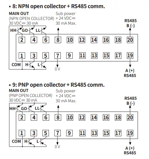
| 8 | NPN open collector quintuple | RS485 comm. | |
| 9 | PNP open collector quintuple | RS485 comm. | |
Dimensions
- Unit: mm, For the detailed drawings, follow the Autonics website.
- This dimensions shows the indicator. The connector (side length) is different according to the output specification.
■ MP5S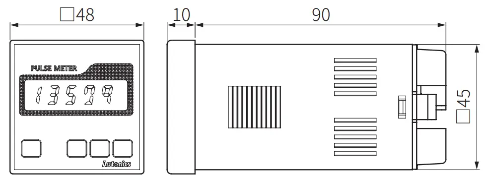 ■ MP5Y
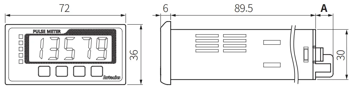 ■ MP5W
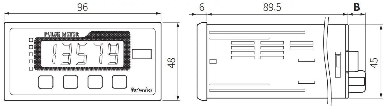
| MP5Y-□N | MP5Y-□1/2/3/4/5 | MP5Y-□6 | MP5W-□N | MP5W-□A/1 | MP5W-□2/4/5/8/9 | |
| A | 10.5 | 14.5 | 15.3 | – | – | – |
| B | – | – | – | 10.5 | 10.5 | 14.5 |
■ Bracket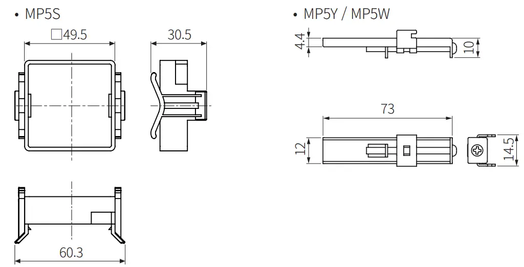 ■ Panel cut-out
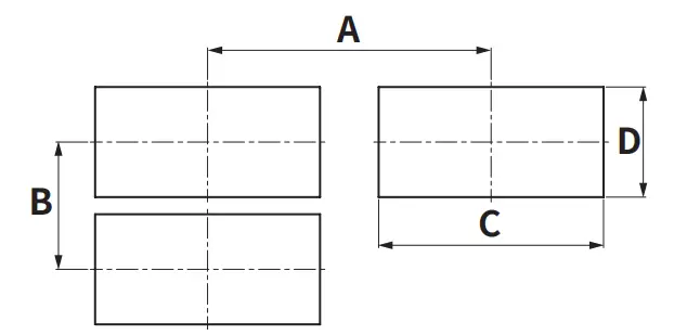
| A | B | C | D | |
| MP5S | ≥ 65 | ≥ 65 | 45 + 0.50 | 45 + 0.50 |
| MP5Y | ≥ 91 | ≥ 40 | 68 + 0.70 | 31.5 + 0.50 |
| MP5W | ≥ 116 | ≥ 52 | 92 + 0.80 | 45 + 0.60 |
Manual
For proper use of the product, refer to the manuals and be sure to follow the safety considerations in the manuals.
Download the manuals from the Autonics website.
Software
Download the installation file and the manuals from the Autonics website.
■ DAQ Master
It is the comprehensive device management program for Autonics’ products, providing parameter setting, monitoring and data management.
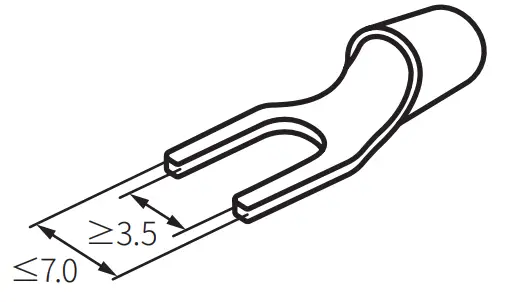
Cautions during Wiring
- Unit: mm, Use terminals of size specified below.

- Contact the manufacture for the socket and cable.
| Model | Specification | Manufacture | |
| MP5Y- □1 / 2 / 3 / 4 / 5 | Hirose connector | HIF3BA-10PA-2.54DS | Hirose Electric |
| Applied connector socket | HIF3BA-10D-2.54R | ||
| MP5W – □2 / 4 / 5 / 8 / 9 | Hirose connector | HIF3BA-20PA-2.54DS | Hirose Electric |
| Applied connector socket | HIF3BA-20D-2.54R | ||
| I / O cable (sold saparately) | CO20-HP□-□ | Autonics | |
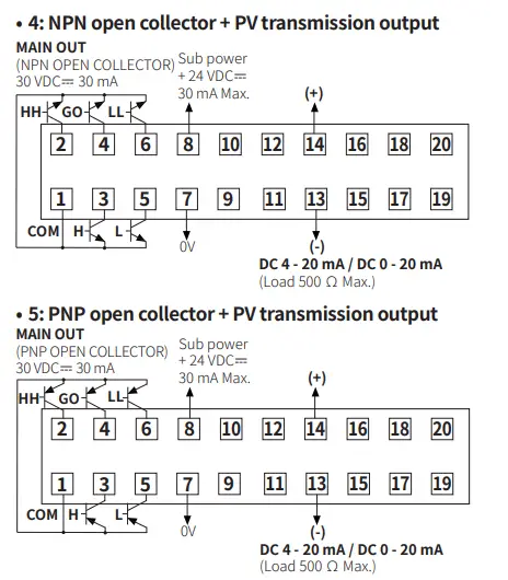
Connections
- Indicator model supports only power / input terminals.
- Connector or terminal block support varies by model. Refer to the cautions during wiring.
- HOLD / RESET terminal function is different depending on the operation mode.
(F1 to F12: HOLD, F13 to F16: RESET)
■ MP5S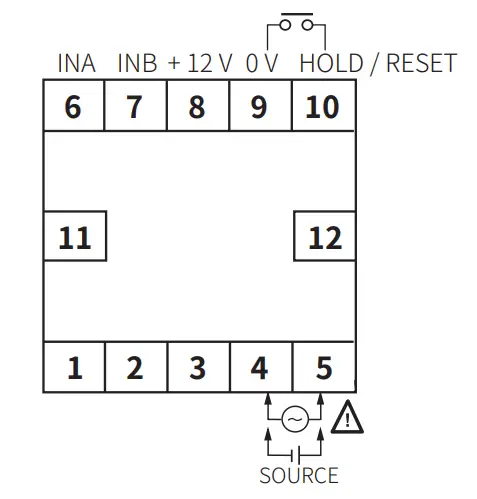 ■ MP5Y
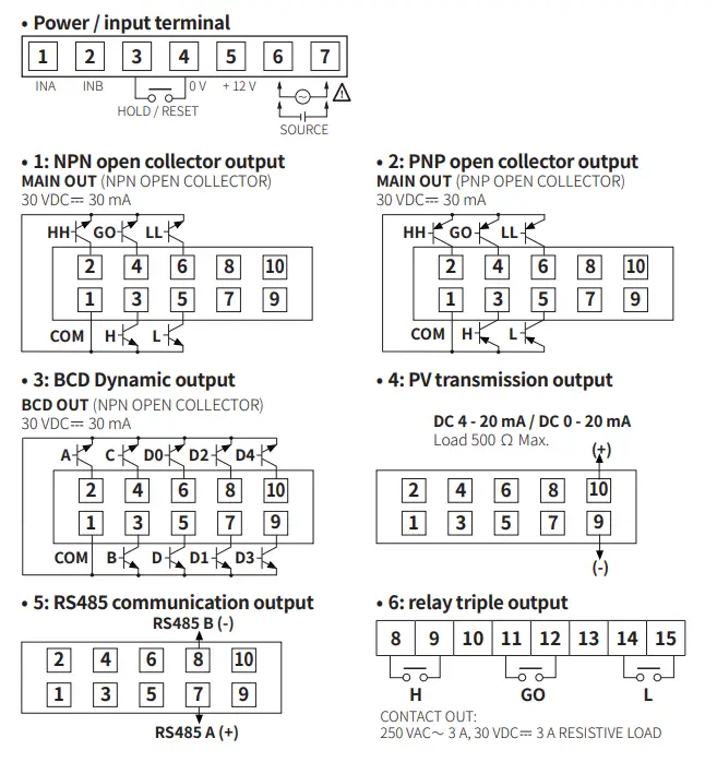 ■ MP5W
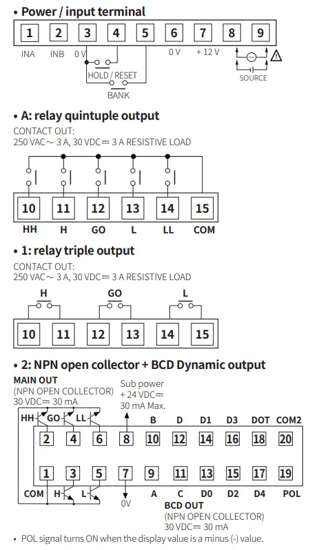
Specifications
| Series | MP5S | MP5Y | MP5W |
| Input signal 01) | Solid state input 1: ≤ 50 kHz (pulse width: ≥ 10 ㎲) Solid state input 2 02): ≤ 5 kHz (pulse width: ≥ 100 ㎲) Contact input: ≤ 45 Hz (contact: 12 VDC | ||
| Voltage input | Input impedance: 3.9 kΩ, [H]: 4.5 – 24 VDC | ||
| No-voltage input | Short-circuit impedance: ≤ 80 Ω, residual voltage: ≤ 1 VDC | ||
| Display method | 7-segment LED (zero blanking method) | ||
| Character size | W 4 × H 8 mm | W 7 × H 14 mm | |
| Prescale | 0.0001 × 10⁻⁹ to 9.9999 × 10⁹ | ||
| Hysteresis | 0 to 9999 03) | ||
| Display cycle | OFF 04), 0.05, 0.5, 1, 2, 4, 8 sec (same as update output cycle) | ||
| Display range | -19999 to 99999 | ||
| Output | Depending on models | ||
| Relay | 250 VAC ∼ 3 A, 30 VDC | ||
| NPN / PNP open collector | ≤ 30 VDC | ||
| BCD Dynamic | NPN open collector ≤ 30 VDC | ||
| PV transmission | DC 4 – 20 mA (load: ≤ 500 Ω, resolution: 8,000 divisions) / DC 0 – 20 mA (load: ≤ 500 Ω, resolution: 10,000 divisions) | ||
| RS485 communication | Modbus RTU | ||
| Product components | Product, instruction manual | ||
| Bracket | Mounted | × 2 | × 2 |
| Unit sticker | × 1 | × 1 | × 2 |
| Unit weight (package) | ≈ 132 g (≈ 191 g) | ≈ 140 g (≈ 230 g) | ≈ 210 g (≈ 334 g) |
| Approval | |||
- Standard duty ratio 1:1
- Operation mode F7, F8, F9, F10: ≤ 1 kHz (pulse width: ≥ 500 ㎲)
- The hysteresis setting range varies according to the decimal point setting position.
- Only available operation mode F2, F16
| AC voltage | AC / DC voltage | |
| Power supply | 100 – 240 VAC ∼ ± 10 % 50 / 60 Hz | 24 VAC ∼ ± 10 % 50 / 60 Hz, 24 – 48 VDC |
| Power consumption | Depending on Series / power supply | |
| MP5S | ≤ 7.5 VA | AC: ≤ 6 VA, DC: ≤ 4.5 W |
| MP5Y | ≤ 9 VA | AC: ≤ 7 VA, DC: ≤ 6.2 W |
| MP5W | ≤ 15 VA | AC: ≤ 11 VA, DC: ≤ 7 W |
| External power supply | ≤ 12 VDC | |
| Sub power supply” | ≤ 24 VDC | |
| Memory retention | Number of inputs: 100,000 operations (non-volatile semiconductor memory type) | |
| Relay life cycle | Mechanical: ≥ 10,000,000 operations (switching frequency 180 operations / min) Electrical: ≥ 100,000 operations (250 VAC | |
| Insulation resistance | ≥ 100 MΩ (500 VDC | |
| Dielectric strength | 2,000 VAC ∼ 60 Hz for 1 min | |
| Noise immunity | ±2 kV the square wave noise (pulse width: 1㎲) by the noise simulator | |
| Vibration | 0.75 mm double amplitude at frequency of 10 to 55 Hz in each X, Y, Z direction for 1 hour | |
| Vibration (malfunction) | 0.5 mm double amplitude at frequency of 10 to 55 Hz in each X, Y, Z direction for 10 min | |
| Shock | 300m / s² (≈ 30G) in each X, Y, Z direction for 3 times | |
| Shock (malfunction) | 100m / s² (≈ 30G) in each X, Y, Z direction for 3 times | |
| Ambient temperature | -10 to 50 °C, storage: -20 to 60 °C (no freezing or condensation) | |
| Ambient humidity | 35 to 85 %RH, storage: 35 to 85 %RH (no freezing or condensation) | |
01) Only for MP5W
| Operation mode | Measurement range | Measurement accuracy (23 ± 5 ℃) | |
| F1 | Frequency / revolutions / speed | 0.0005 Hz to 50 kHz | F.S. ± 0.05 % rdg ± 1 digit |
| F2 | Passing speed | ||
| F3 | Cycle | 0.01 to max. of each time range | F.S. ± 0.01 % rdg ± 1 digit |
| F4 | Passing time | ||
| F5 | Time interval | ||
| F6 | Time differential | ||
| F7 | Absolute ratio | 0.0005 Hz to 50 kHz | F.S. ± 0.05 % rdg ± 1digit |
| F8 | Error ratio | ||
| F9 | Density | ||
| F10 | Error | ||
| F11 | Length measurement 1 | 0 to 99999 | – |
| F12 | Interval | ||
| F13 | Accumulation | ||
| F14 | Addition / subtraction- individual input | -19999 to 99999 | |
| F15 | Addition / subtraction-phase difference input | ||
| F16 | Length measurement 2 | 0 to 99999 | |
Communication Interface
■ RS485
| Comm. protocol | Modbus RTU (16-bit CRC) |
| Application standard | Compliance with EIA RS485 |
| Max. connection | 31-unit (address: 1 to 127) |
| Comm. synchronous method | Asynchronous |
| Comm. method | 2-wire half duplex |
| Comm. distance | ≤ 800 m |
| Comm. speed | 2,400 / 4,800 / 9,600 (default) / 19,200 / 38,400 bps |
| Comm. response time | 5 to 99 ms (default: 20 ms) |
| Start bit | 1-bit (fixed) |
| Data bit | 8-bit (fixed) |
| Parity bit | None (default), Even, Odd |
| Stop bit | 1-bit, 2-bit (default) |
Mode Setting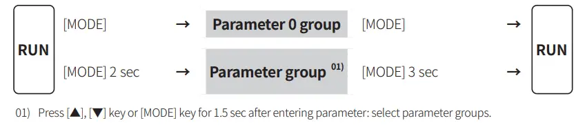 Parameter Setting
- Some parameters are activated / deactivated depending on the model or setting of other parameters. Refer to the description of each parameter.
- The parameter and setting value are cross-displayed on the display part.
- If any key is not entered for 60 sec in each parameter, it returns to RUN mode.
- [MODE] key: Saves current setting value and moves to the next parameter.
[◀] key: Checks fixed value / Changes setting digits.
[▲], [▼] key: Changes setting values.
■ Parameter 0 group
| Parameter | Display | Default | Setting range | Displaycondition | |
| HH P0-1 comparative value | [Comparative value output model “J | P1-4 Output mode: except F | |||
| Operation mode | Setting range | ||||
| Fl, F2, F7, F9, F11, F12, F13, F16 | 0 to 99999 | ||||
| – | |||||
| H comparative P0- 2 value | |||||
| F3, F4, F5, F6 | 0.01 to time settin: ran:e | ||||
| – | |||||
| L comparative P0-3 value | |||||
| F8, F10, F14, F15 | -19999 to 99999 | ||||
| •Varies according to P1-1 Input operation mode and P2-2 Decimal point position of display value •Same parameters at parameter 2 group are linked. | |||||
| P1-4 Output mode: except F | |||||
| LL comparative P0-4 value | |||||
| Max. P0-5 monitoring value | Reset (PV): [◀ ] key for over 2 sec | P1-1 Input operation mode: except F13, F16 | |||
| Min. P0-6 monitoring value | |||||
01)
| Parameter | Comparative value output model | |
| Quintuple | Triple | |
| HH comparative value | – | |
| H comparative value | ||
| L comparative value | ||
| LL comparative value | – | |
■ Parameter 1 group
| Parameter | Display | Default | Setting range | Display condition |
| Input P1-1 operation mode | Fl to F16 | – | ||
| Input A sensor type P1-2 | NPN.H.F :NPN non-contact inputl NPN.M.F : NPN non-contact inputl NPN.L.F : NPN contact input PNP.H.F : PNP non-contact inputl PNP.M.F : PNP non-contact input2 PNP.LF : PNP contact input | – | ||
| Input B sensor type P1-3 | P14 Input operation mode: F2, F6 to 14, F16 ”n | |||
| P1-4 Output mode | [Comparative value output model] STARD : S (Standard) OUT-H : H (High) OUT-L: L (Low) OUT-B: B (Block) OUT-I : I (One-shot) OUT-F: F (Deflection)* | P14 Input operation mode: except F13 & •P14 Input operation mode: except F16 | ||
| Output P1-5 hysteresis | [Comparative value output model] 0000 to 9999 •Varies according to P2-2 Decimal point position of display value | P14 Input operation mode: Fl, F7 to 10 | ||
| Delay P1-6 monitoring | [Comparative value output model] F.DEFY: LL, L comparative output limit’ START: Start compensation timer’ | P1-1 Input operation mode: Fl to 12 *P1-4 Output mode: S, B, F | ||
| Start P1-7 compensation timer | [Comparative value output model] 0.0 to 99.9 sec | P1-6 Delay monitor ng: START | ||
| Input A auto- P1-8 zero time | 0.1 to 9999.9 sec | P14 Input operation mode: Fl, F4, F7 to 10 | ||
| Input B auto- P1-9 zero time | P14 Input operation mode: F7 to 10 | |||
| Memory P1-10 retention | OFF,ON | P14 Input operation mode: F13 to 16 |
01) In case of P1-1 Input operation mode F15, input B sensor type is not displayed and IN-B setting is same as IN-A. 02) [▲] key: Entering compensation time setting
■ Parameter 2 group
| Parameter | Display | Default | setting range Display | condition |
| P2-1 Data bank | [M P5W model] 1, 2 | – | ||
| Decimal point P2-2 position of display value | 00000,0000.0,000.00,00.000, 0.0000 | P1-1 Input operation mode: Fl to 2,F7 to 16 | ||
| P2-3 Time unit” | T.SEC, T.MIN | P1-1 Input operationmode: F3 to 6 | ||
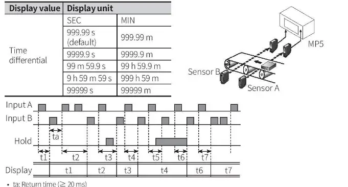
| P24 Time range (unit: sec)” | 999.99: 999.99 s 9999.9: 9999.9 s 99.59.9: 99 m 59.9 s 9.59.59:9 h 59 m 59 s 99999: 99999 s | |||
| P25 Time range (unit: min) | 999.99: 999.99 m 9999.9: 9999.9 m 99.59.9: 99 h 59.9 m 9.59.59: 999 h 59 m 99999: 99999 m | |||
| HH P2-6 comparative value | [Comparative value output model) linked with parameter 0 group parameters | P1-4 Output mode: except F | ||
| P2-7 H comparative value | – | |||
| P2-8 L comparative value | – | |||
| P2-9 LL comparative value |  | P1-4 Output mode: except F | ||
| Input A P2-10 prescale mantissa (x) | 0.0001 to 9.9999 | P1-1 Input operation mode: Fl to 2, F4, | ||
| Input A P2-11 prescale exponent (y) | F7 to 16 10- 9 (109) to 10 09 (109) | |||
| Input B P2-12 prescale mantissa (x) | 0.0001 to 9.9999 | P1-1 Input operation F7 to 10 | ||
| Input B P2-13 prescale exponent (y) | mode: 10- 9 (109) to 10 09 (109) | |||
| P2-14 Display cycle | OFF” or 0.05, 0.5, 1, 2, 4, 8 sec | P1-1 Input operation mode: Fl to 2, F7 to 10, F16 | ||
| Input B P2-15 setting value (INB) |  | 1 to 99999 | P1-1 Input operation mode: F16 |
01) To enter P2-4 time range (unit: sec) and P2-5 time range (unit: min) setting, press [▲] key at P2-3 time unit.
02) Only available operation mode F2, F16
■ Parameter 3 group
| Parameter | Display | Default | Setting range | Display condition | |
| Max. PV P3-1 transmission output value | [PV transmission (current) output model] min. value to max. value (FS-H? FS-L + 1) | _ | |||
| Operation mode | Setting range | ||||
| Fl, F2, F7, F9, Ell, F12, F13, F16 | 0 to 99999 | ||||
| F3, F4, F5, F6 | 0.01 to time setting range | ||||
| Min. PV P3-2 transmission output value | – | ||||
| F8, F10, F14, F15 | -19999 to 99999 | ||||
| •Varies according to P1-1 Input operation mode and P2-2 Decimal point position of displayvalue | |||||
| P3-3 current output | [PV transmission (current) output model] 4-20, 0-20 mA | _ | |||
| P34 Comm. address | |||||
| [RS485 communication output model] 01 to 99 | – | ||||
| Comm. P3-5 speed | [R5485 communication output model] 2400, 4800, 9600, 19200, 38400 bps | – | |||
| Comm. parity P3-6 bit | [RS485 communication output model] NONE, EVEN, ODD | – | |||
| P3-7 Comm. stop bit | [RS485 communication output model] 1, 2 | – | |||
| Comm. P3-8 response waiting ime | [RS485 communication out •ut model] | – | |||
| Comm. speed | Setting range | ||||
| 2400 bps | 16 to 99 ms | ||||
| 4800 bps | 8 to 99 ms | ||||
| 9600, 19200, 38400 bps | 5 to 99 ms | ||||
| •Setting range varies according to P3-5 Comm. speed | |||||
| P3-9 Comm. write | IRS485 communication output model] ENA: enable, DISA: disable | – | |||
| P3-10 Lock | OFF : Unlock LOC.0 : Lock All LOC.1 : Lock parameter 1/2 / 3 LOC.2 : Lock parameter 2/ 3 LOC.3 : Lock parameter 3 | – | |||
| Parameter P3-11 reset | ENA: enable, DISA: disable | – | |||
Output Mode
Output mode is available to set. (Indicator does not support output mode.)

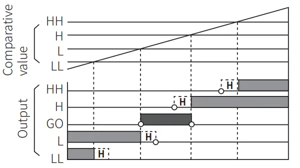
■ S (Standard) output mode
- Comparative value setting condition: individual output operation regardless of size or order of set comparative values
HH output: H output: L output: LL output: GO output:
Display value Comparative value RH Display value Comparative value H Display value Comparative value L Display value •S Comparative value LL No HH, H, L, LL output
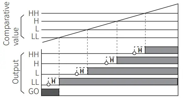
■ H (High) output mode
- Comparative value setting condition: individual output operation regardless of size or order of set comparative values
HH output: H output: L output: LL output: GO output:
Display value > Comparative value HH Display value > Comparative value H Display value > Comparative value L Display value > Comparative value LL No HH, H, L, LL output
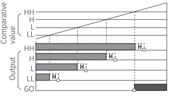
■ L (Low) output mode
- Comparative value setting condition: individual output operation regardless of size or order of set comparative values
HH output: H output: L output: I L output: GO output:
Display value Display value Display value Display value No HH, H, L, LL output
5 Comparative value HH 5 Comparative value H 5. Comparative value L 5 Comparative value LL
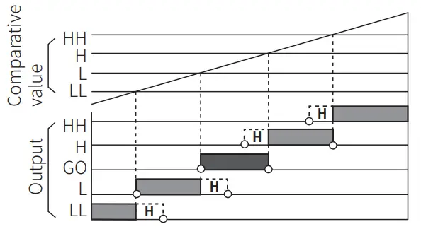
■ B (Block) output mode
- Comparative value setting condition: LL<L<H<HH
HH output: Display value Comparative value NH H output: Comparative value HH > Display value Comparative value H L output: Comparative value LL < Display value 5 Comparative value L LL output: Display value 5 Comparative value LL GO output: No HH, H, L, LL output
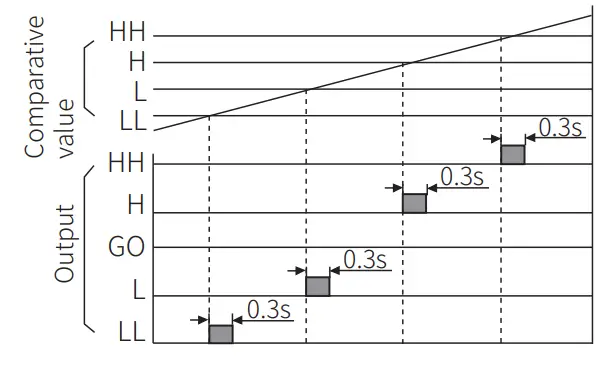
■ I (One-shot) output mode
- Comparative value setting condition: individual output operation regardless of size or order of set comparative values
- One-shot output time: 0.3 sec (fixed)
- No GO output.
- No hysteresis.
HH output: Display value Comparative value 14H H output: Comparative value HH ≥Display value Comparative value H L output: Comparative value H ≥ Display value .? Comparative value L LL output: Comparative value L≥ Display value Comparative value LL
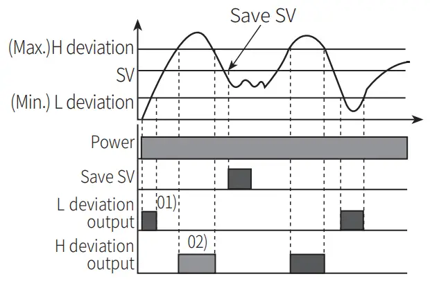
■ F (Deflection) output mode
- Transmits outputs when the saved setting value exceeds H deviation or L deviation.
- Comparative value setting : Based on the set value, set the H / L deviation in the P0-2, P2-7 H comparative value and P0-3, P2-8 L comparative value parameters. (The set deviation value is saved during Power OFF until it is re-set.)
- Comparative value setting range : 0.0001 to 99999 The setting range is different according to the P2-2 Decimal point position of display value setting. E.g.) In case of P2-2 Decimal point position of display value = 0000.0, setting range = 0.1 to 9999.9
- Saving setting value: [MODE] + [▲]
- Checking setting value: [▲]
- No HH, GO, LL output.
- The deviation can be set to “0” but the actual operation will be the same as “1”.
Operation Mode
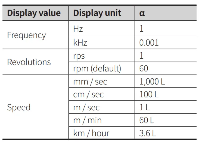
■ Fl: frequency / revolutions / speed
Measures the frequency of input A and displays the calculated frequency, revolutions, and speed.
Frequency (Hz) = f x a (a =1 [sec])
Revolutions (rpm) = f x a (a = 60 [sec])
Speed (m / min) = f x a (a = 60 L [sec])
- L: travel distance of conveyor belt of 1 cycle [m]
- a: presca le value (For multiple objects, a= 60L/ N)
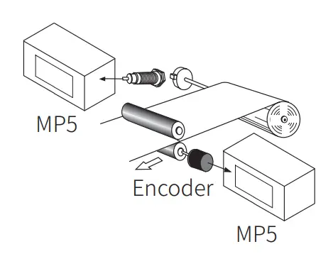
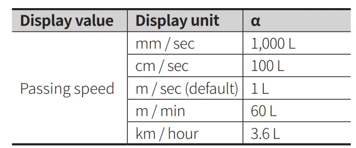
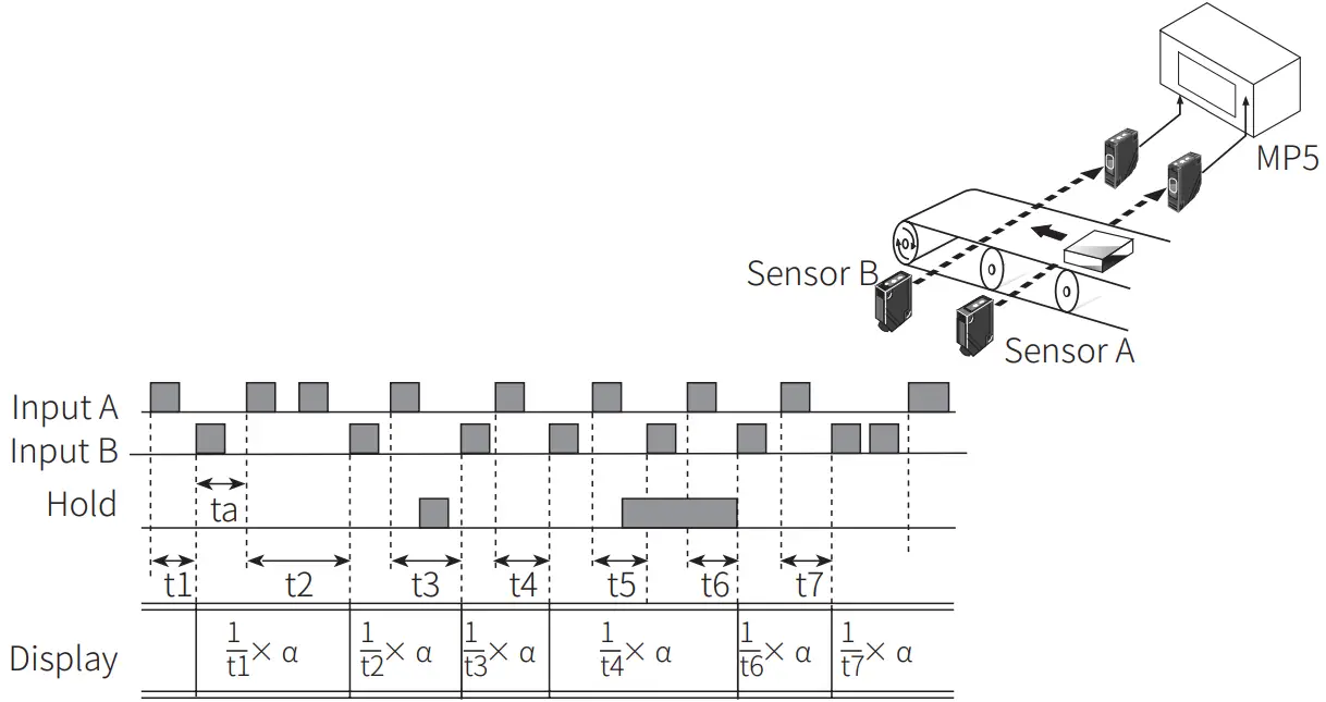
■ F2: passing speed
Displays the passing speed between input A ON and input B ON.
Passing speed (V) = f x a (a = L [m])
- f : reciprocal of time [sec] between input A (sensor) ON and input B( sensor) ON.
- L: distance between input A (sensor) and input B (sensor) [m]
- a: presca le value
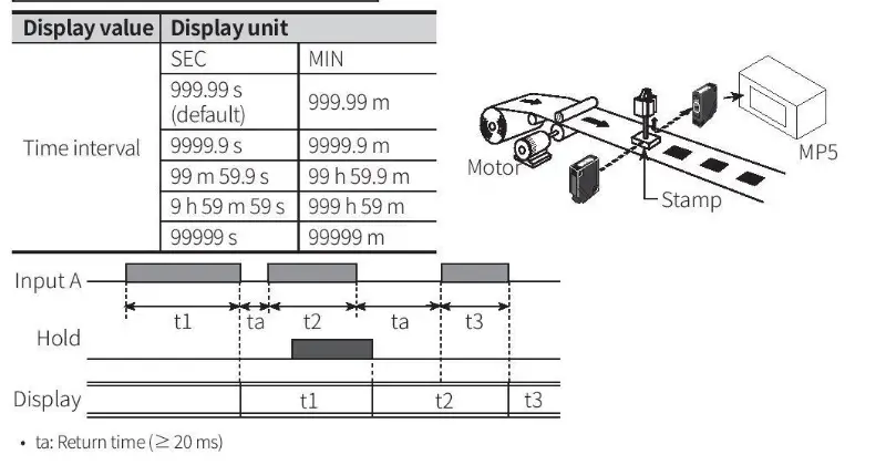
■ F5: time interval
Displays measured time of input A ON.
Time interval (T) = t
- t: measured t i m e of input A ON [sec]
■ F6: time differential
Displays measured t i m e from Input
A ON t o Input B ON.
Time differential (T) =t (ta to tb)
- t (ta to tb): measured time from input AON to input B ON [sec]
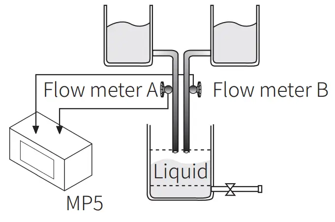
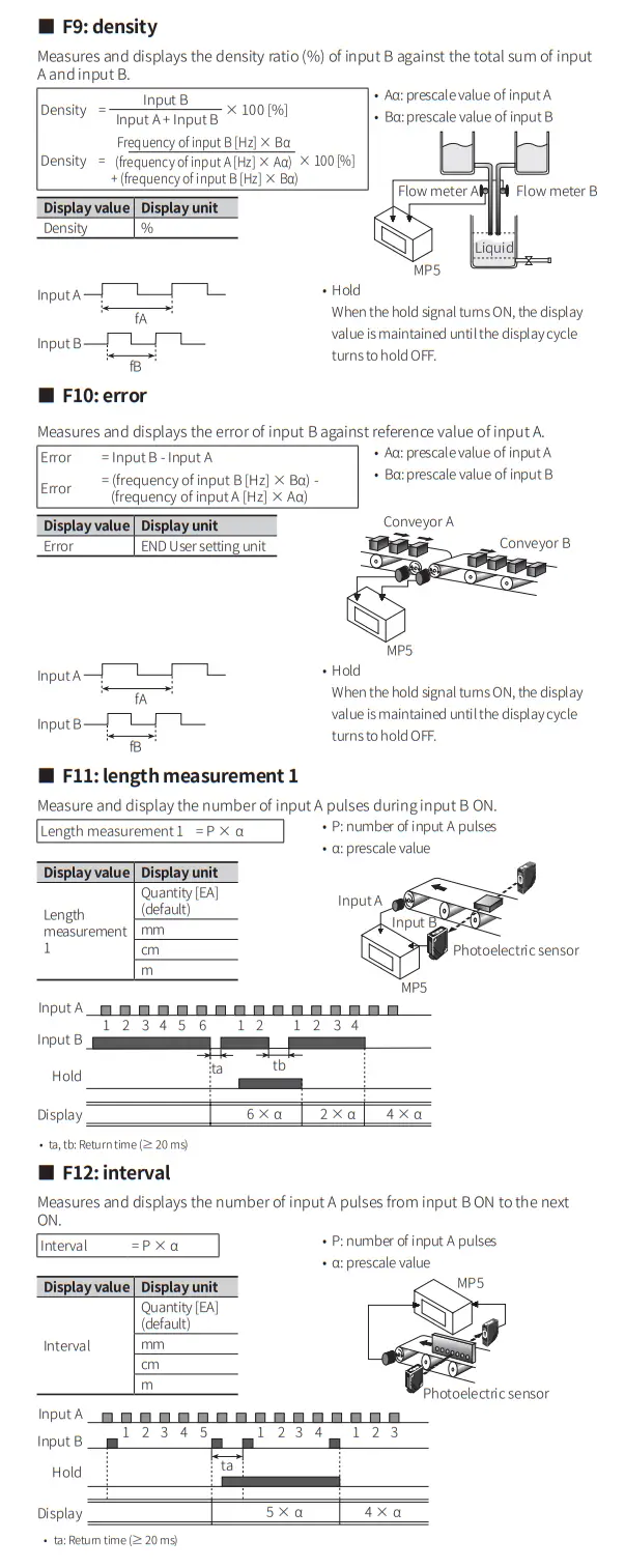
■ F7: absolute ratio
Measures and displays relative speed, am in percentage (%). ount, speed , etc. of input B against input A
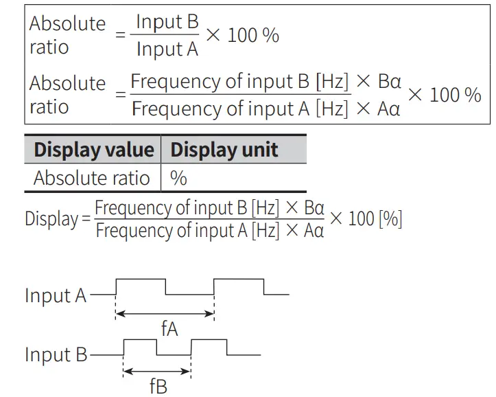
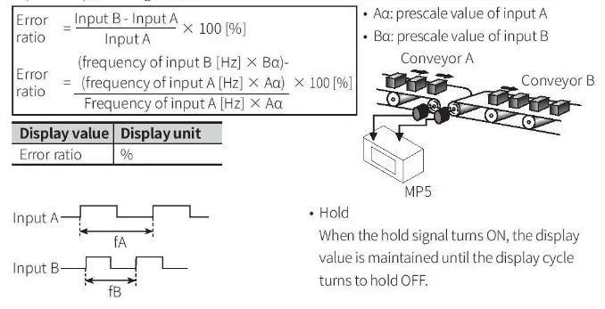
- Aa: prescale value of input A
- Ba: prescale value of input B

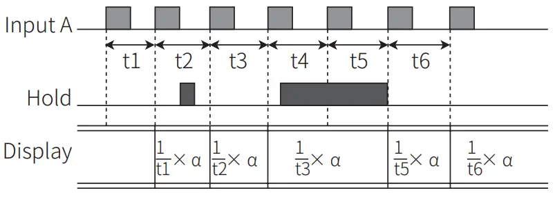
- Hold
When the hold signal turns ON, the display value i s maintained until the display cycle turns to hold OFF.
■ F8: error ratio
Measures and displays the relative rate of input B against the reference value of
Functions
■ Hysteresis
Near the comparative setting value, the output may turn ON / OFF frequently and unstably. To prevent this. hysteresis value is set based on the comparative setting value.
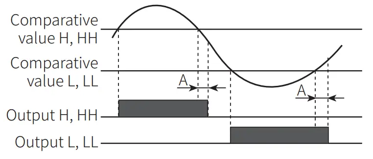
- A: hysteresis
- The hysteresis value can be set to “0” but the actual operation value is “1”
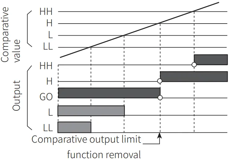
■ Delay monitoring: limit comparative output
After supplying power, the starting current of motors and other inputs are changeable. This function allows stable control by limiting all outputs for a certain period of time, until the target measurement unit stabilizes. It may also control L,LL outputs until a specific output is reached.
- After supplying power, there is no initial L, LL comparative outputs.
- Each setting value of HH, H, LL, L is not related to their relative sizes.
- E.g.: S (Standard) output mode

- E.g.: F (Deflection) output mode
The comparative output limiting function is removed at the set value (standard setting). Comparative output limit
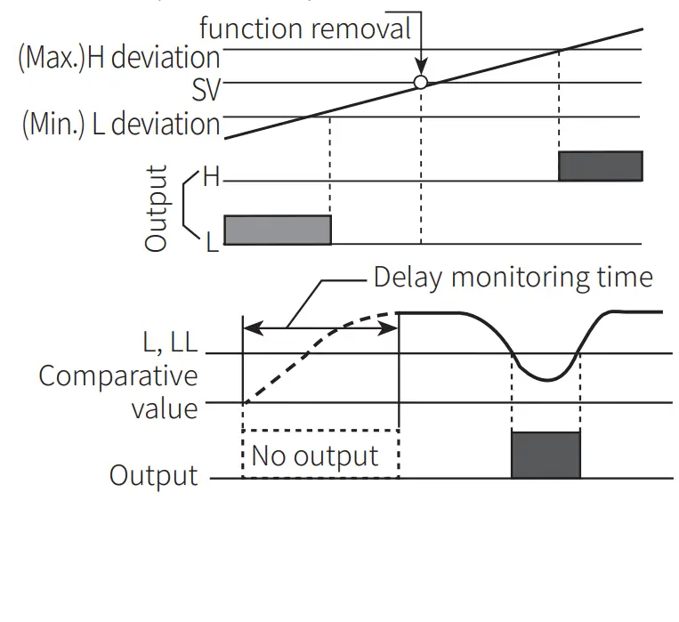
■ Delay monitoring: Start compensation timer
Set monitoring delay time so that there is no output during the delay time.
■ Auto-zero time
When there is no input signal during auto-zero setting time, the display value is automatically set to 0(zero). Please set the auto-zero setting time so that it is longer than the interval of the slowest input signal. If the setting time is too long and there is no input signal, the rate at which the display value falls to 0(zero) decrease, and output response rate may slow down.
■ Data bank
Comparative setting value and prescale value are saved as two types(data bank 1, 2) and can be selected for use by opening or shorting of terminals.
- Terminal 3, 5 open: use value of data bank 1
- Terminal 3, 5 short use value of data bank 2
■ Prescale
Displays values in required units or specific multiples by counting the number of input pulses, then multiplying the number of pulses or the length of pulses by variables (X x 10y).
- E.g.: prescale value (a = 15) setting
- f: the number of input pulses per second [Hz]
- a: prescale value
- N: the number of pulses per revolution Set mantissa(X) as 1.5000, and exponent(Y) as 1 for prescale value(a)=15. The same display value can be obtained with a value set as X=0.1500, and Y=2
Revolutions (rpm)
= f x a
=f X 60 X (1/N)
= f x 60 X (1 / 4)
= f X 60 X 0.25
= f X 15
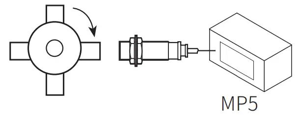
Example of Input Connection
| NPN input | 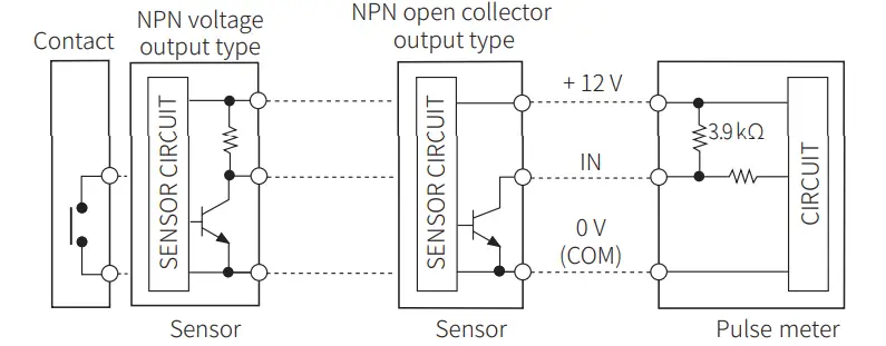 |
| PNP input | 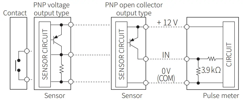 |
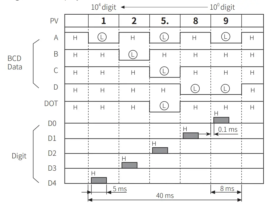
BCD Dynamic Output (negative logic)
- BCD Data (A, B, C, D, DOT) <A: lowest bit, DOT: highest bit Digit Data ( D O , D1, D2, D3, D4) < DO: lowest digit, D4: highest digit
- E.g.: 125.89 Display
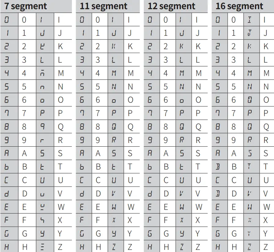
Segment Table
The segments displayed on the product indicate the following meanings. It may differ depending on the product.
![]() 18, Bansong-ro 513Beon-gil, Haeundae-gu, Busan, Republic of Korea, 48002
18, Bansong-ro 513Beon-gil, Haeundae-gu, Busan, Republic of Korea, 48002
www.autonics.com | +82-51-519-3232 | [email protected]


