![]() USER MANUAL
USER MANUAL
SMART SERIES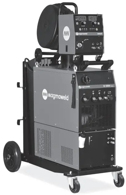
SMART SERIES
25207 Smart Pulse
All rights reserved. It is prohibited to reproduce this documentation, or any part thereof, without the prior written authorisation of Magma Mechatronic Machine Sanayi vet Tricare A.Ş.
 SAFETY PRECAUTIONS
Be Sure To Follow All Safety Rules In This Manual!
![]() Explanation Of Safety Information
Explanation Of Safety Information
- Safety symbols found in the manual are used to identify potential hazards.
- When any one of the safety symbols are seen in this manual, it must be understood that there is a risk of injury and the following instructions should be read carefully to avoid potential hazards.
- The possessor of the machine is responsible for preventing unauthorized persons from accessing the equipment.
- Persons using the machine must be experienced or fully trained in welding / cutting they have to read the user manual before operation and follow the safety instructions.
![]() Explanation Of Safety Symbols
Explanation Of Safety Symbols
ATTENTION![]() Indicates a potentially hazardous situation that could cause injury or damage.
Indicates a potentially hazardous situation that could cause injury or damage.
In case if no precaution is taken, it may cause injuries or material losses / damages.
IMPORTANT![]() Specifies notifications and alerts on how to operate the machine.
Specifies notifications and alerts on how to operate the machine.
DANGER![]() Indicates a serious danger. In case if not avoided, severe or fatal injuries may occur.
Indicates a serious danger. In case if not avoided, severe or fatal injuries may occur.
![]() Comprehending Safety Precautions
Comprehending Safety Precautions
- Read the user manual, the label on the machine and the safety instructions carefully.
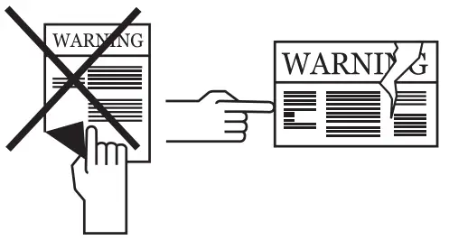
- Make sure that the warning labels on the machine are in good condition. Replace missing and damaged labels.
- Learn how to operate the machine, how to make the checks in a correct manner.
- Use your machine in suitable working environments.
- Improper changes made in your machine will negatively affect the safe operation and its longevity.
- The manufacturer is not responsible for the consequences resulting from the operation of the device beyond the specified conditions.
![]() Electric Shocks May Kill
Electric Shocks May Kill
Make certain that the installation procedures comply with national electrical standards and other relevant regulations, and ensure that the machine is installed by authorized persons.
- Wear dry and sturdy insulated gloves and working apron. Never use wet or damaged gloves and working aprons.
- Wear flame-resistant protective clothing against the risk of burning. The clothing used by the operator must be protective against sparks, splashing and arc radiation.
- Do not work alone. In case of a danger make sure you have someone for help in your working environment.
- Do not touch the electrode with the bare hand. Do not allow the electrode holder or electrode to come in contact with any other person or any grounded object.
- Never touch parts that carry electricity.
- Never touch the electrode if you are in contact with the electrode attached to the work surface, floor or another machine.
- By isolating yourself from the work surface and the floor, you can protect yourself from possible electric shocks. Use a non-flammable, electrically insulating, dry and undamaged insulation material that is large enough to cut off the operator’s contact with the work surface.
- Do not connect more than one electrode to the electrode holder.
- Clamp work cable with good metal-to-metal contact to workpiece or worktable as near the weld as practical.
- Check the torch before operating the machine. Make sure the torch and its cables are in good condition. Always replace a damaged, worn torch.
- Do not touch electrode holders connected to two machines at the same time since double open-circuit voltage will be present.
- Keep the machine turned off and disconnect cables when not in use.
- Before repairing the machine, remove all power connections and / or connector plugs or turn off the machine.
- Be careful when using a long mains cable. Make sure all connections are tight, clean, and dry.
- Keep cables dry, free of oil and grease, and protected from hot metal and sparks.
- Bare wiring can kill. Check all cables frequently for possible damage. If a damaged or an uninsulated cable is detected, repair or replace it immediately.
- Insulate work clamp when not connected to workpiece to prevent contact with any metal object.
- Make sure that the grounding of the power line is properly connected.
- Do not use AC weld output in damp, wet, or confined spaces, or if there is a danger of falling.
- Use AC output ONLY if required for the welding process.
- If AC output is required, use remote output control if present on unit.
Additional safety precautions are required when any of the following electrically hazardous conditions are present : - in damp locations or while wearing wet clothing,
- on metal structures such as floors, gratings, or scaffolds,
- when in cramped positions such as sitting, kneeling, or lying,
- when there is a high risk of unavoidable or accidental contact with the workpiece or ground.
For these conditions, use the following equipment in order presented: - Semiautomatic DC constant voltage (CV) MIG welding machine,
- DC manual MMA welding machine,
- DC or AC welding machine with reduced open-circuit voltage (VRD), if available.
![]() Procedures for Electric Shock
Procedures for Electric Shock
- Turn off the electric power.
- Use non-conducting material, such as dry wood, to free the victim from contact with live parts or wires.
- Call for emergency services.
If you have first aid training; - If the victim is not breathing, Administer cardiopulmonary resuscitation (CPR) immediately after breaking contact with the electrical source. Continue CPR (cardiac massage) until breathing starts or until help arrives.
- Where an automatic electronic defibrillator (AED) is available, use according to ins tractions.
- Treat an electrical burn as a thermal burn by applying sterile, cold (iced) compresses. Prevent contamination, and cover with a clean, dry dressing.
![]() Moving Parts May Cause Injuries
Moving Parts May Cause Injuries
- Keep away from the moving parts.
- Keep all protective devices such as covers, panels, flaps, etc., of machinery and equipment closed and in locked position.
- Wear metal toe shoes against the possibility of heavy objects falling on to your feet.
![]() Fumes and Gases May Be Harmful To Your Health
Fumes and Gases May Be Harmful To Your Health
Long-term inhalation of fumes and gases released from welding / cutting is very dangerous.
- Burning sensations and irritations in the eyes, nose and throat are signs of inadequate ventilation. In such a case, immediately boost the ventilation of the work area, and if the problem persists, stop the welding / cutting process completely.
- Create a natural or artificial ventilation system in the work area.
- Use a suitable fume extraction system where welding / cutting works are being carried out. If necessary, install a system that can expel fumes and gases accumulated in the entire workshop.
Use a suitable filtration system to avoid polluting the environment during discharge. - If you are working in narrow and confined spaces or if you are welding lead, beryllium, cadmium, zinc, coated or painted materials, use masks that provide fresh air in addition to the above precautions.
- If the gas tanks are grouped in a separate zone, ensure that they are well ventilated, keep the main valves closed when gas cylinders are not in use, pay attention to possible gas leaks.
- Shielding gases such as argon are denser than air and can be inhaled instead of air if used in confined spaces. This is dangerous for your health as well.
- Do not perform welding / cutting operations in the presence of chlorinated hydrocarbon vapors released during lubrication or painting operations.
- Some welded / cut parts require special ventilation. The safety rules of products that require special ventilation should be read carefully. A suitable gas mask should be worn when necessary.
![]() Arc Light May Damage Your Eyes and Skin
Arc Light May Damage Your Eyes and Skin
- Use a standard protective mask and a suitable glass filter to protect your eyes and face.
- Protect other naked parts of your body (arms, neck, ears, etc.) with suitable protective clothing from these rays.
- Enclose your work area with flame-resistant folding screens and hang warning signs at eye level so that people around you will not sustain injuries from arc rays and hot metals.
- This machine is not used for heating of icebound pipes. This operation performed with the welding / cutting machine causes explosion, fire or damage to your installation.
![]() Sparks and Spattering Particles May Get Into Eyes and Cause Damage
Sparks and Spattering Particles May Get Into Eyes and Cause Damage
- Performing works such as welding / cutting, surface grinding, and brushing cause sparks and metal particles to splatter. Wear approved protective work goggles which have edge guards under the welding masks to prevent sustaining possible injuries.
![]() Hot Parts May Cause Severe Burns
Hot Parts May Cause Severe Burns
- Do not touch the hot parts with bare hands.
- Wait until the time required for the machine to cool down before working on its parts.
- If you need to hold hot parts, use suitable tools, welding / cutting gloves with high-level thermal insulation and fire-resistant clothes.
![]() Noise May Cause Damage To Your Hearing Ability
Noise May Cause Damage To Your Hearing Ability
- The noise generated by some equipment and operations may damage your hearing ability.
- Wear approved personal ear protective equipment if the noise level is high.
![]() Welding Wires Can Cause Injuries
Welding Wires Can Cause Injuries
- Do not point the torch towards any part of the body, other persons, or any metal while unwrapping the welding / cutting wire.
- When welding wire is run manually from the roller especially in thin diameters the wire can slip out of your hand, like a spring or can cause damage to you or other people around, therefore you must protect your eyes and face while working on this.
![]() Welding Operations May Cause Fire and Explosion
Welding Operations May Cause Fire and Explosion
- Never perform welding / cutting work in places near flammable materials. There may be fire or explosions.
- Before starting the welding / cutting work, remove these materials form the environment or cover them with protective covers to prevent combustions and flaring.
- National and international special rules apply in these areas.
- Do not apply welding / cutting operations into completely closed tanks or pipes.
- Before welding to tanks and closed containers, open them, completely empty them, and clean them. Pay the greatest attention possible to the welding / cutting operations you will perform in such places.
- Do not weld in tanks and pipes which might have previously contained substances that may cause explosions, fires or other reactions.
- Welding / cutting equipment heats up. For this reason, do not place it on surfaces that could easily burn or be damaged !
- Sparks and splashing parts may cause a fire. For this reason, keep materials such as fire extinguishers tubes, water, and sand in easily accessible places.
- Use holding valves, gas regulators and valves on flammable, explosive and compressed gas circuits. Make sure that they are periodically inspected and pay attention that they run reliably.
![]() Maintenance Work Performed by Unauthorized Persons To Machines and Apparatus May Cause Injuries
Maintenance Work Performed by Unauthorized Persons To Machines and Apparatus May Cause Injuries
- Electrical equipment should not be repaired by unauthorized persons.
Errors occurred if failed to do so may result in serious injury or death when using the equipment. - The gas circuit elements operate under pressure; explosions may occur as a result of services provided by unauthorized persons, users may sustain serious injuries.
- It is recommended to perform technical maintenance of the machine and its auxiliary units at least once a year.
![]() Welding / Cutting in Small Sized and Confined Spaces
Welding / Cutting in Small Sized and Confined Spaces
- In small-sized and confined spaces, absolutely make sure to perform welding / cutting operations, accompanied by another person.
- Avoid performing welding / cutting operations in such enclosed areas as much as possible.
![]() Failure To Take Precautions During Transport May Cause Accidents
Failure To Take Precautions During Transport May Cause Accidents
- Take all necessary precautions when moving the machine. The areas where the machine to be transported, parts to be used in transportation and the physical conditions and health of the person carrying out the transportation works should be suitable for the transportation process.
- Some machines are extremely heavy; therefore, make sure that the necessary environmental safety measures are taken when changing their places.
- If the machine is to be used on a platform, it must be checked that this platform has suitable load bearing limits.
- If it is to be transported by means of a haulage vehicle (transport trolley, forklift etc.), make sure of the durableness of the vehicle, and the connection points (carrying suspenders, straps, bolts, nuts, wheels, etc.) that connect the machine to this vehicle.
- If the machine will be carried manually, make sure the durableness of the machine apparatuses (carrying suspenders, straps, etc.) and connections.
- Observe the International Labor Organization’s rules on carriage weights and the transport regulations in force in your country in order to ensure the necessary transport conditions.
- Always use handles or carrying rings when relocating the power-supply sources. Never pull from torches, cables or hoses. Be absolutely sure to carry gas cylinders separately.
- Remove all interconnections before transporting the welding / cutting equipment, each being separately, lift and transport small ones using its handles, and the big ones from its handling rings or by using appropriate haulage equipment, such as forklifts.
![]() Falling Parts May Cause Injuries
Falling Parts May Cause Injuries
Improper positioning of the power-supply sources or other equipment can cause serious injury to persons and physical damage to other objects.
- Place your machine on the floor and platforms with a maximum tilt of 10° so that it does not fall or tip over. Choose places that do not interfere with the flow of materials, where there is no risk of tripping over on cables and hoses; yet, large, easily ventilatable, dust-free areas. To prevent gas cylinders from tipping over, on machines with a gas platform suitable for the tanks, fix the tanks on to the platform; in stationary usage applications, fix them to the wall with a chain in a way that they would not tip over for sure.
- Allow operators to easily access settings and connections on the machine.
![]() Excessive Use Of The Machine Causes Overheating
Excessive Use Of The Machine Causes Overheating
- This device is in group 2, class A in EMC tests according to TS EN 55011 standard.
- This class A device is not intended for use in residential areas where electrical power is supplied from a low-voltage power supply. There may be potential difficulties in providing electromagnetic compatibility due to radio frequency interference transmitted and emitted in such places.
 This device is not compliant with IEC 61000 -3-12. In case if it is desired to be connected to the low voltage network used in the home, the installer to make the electrical connection or the person who will use the machine must be aware that the machine has been connected in such a manner; in this case the responsibility belongs to the user.
 - Make sure that the work area complies with electromagnetic compatibility (EMC).
Electromagnetic interferences during welding / cutting operations may cause undesired effects on your electronic devices and network; and the effects of these interferences that may occur during these operations are under the responsibility of the user. - If there is any interference, to ensure compliance; extra measures may be taken, such as the use of short cables, use of shielded (armored) cables, transportation of the welding machine to another location, removal of cables from the affected device and / or area, use of filters or taking the work area under protection in terms of EMC.
- To avoid possible EMC damage, make sure to perform your welding / cutting operations as far away from your sensitive electronic devices as possible (100 m).
- Ensure that your welding and/or cutting machine has been installed and situated in its place according to the user manual.
![]() Evaluation Of Electromagnetic Suitability Of The Work Area
Evaluation Of Electromagnetic Suitability Of The Work Area
According to article 5.2 of IEC 60974-9;
Before installing the welding / cutting equipment, the person in charge of the operation and / or the user must conduct an inspection of possible electromagnetic interference in the environment.
Aspects indicated below has to be taken into consideration;
a) Other supply cables, control cables, signal and telephone cables, above and below the welding / cutting machine and its equipment,
b) Radio and television transmitters and receivers,
c) Computer and other control hardware,
d) Critical safety equipment, e.g. protection of industrial equipment,
e) Medical apparatus for people in the vicinity, e.g. pacemakers and hearing aids,
f) Equipment used for measuring or calibration,
g) Immunity of other equipment in the environment. The user must ensure that the other equipment in use in the environment is compatible. This may require additional protection measures.
h) Considering the time during which the welding / cutting operations or other activities take place during the day, the boundaries of the investigation area can be expanded according to the size of the building, the structure of the building and other activities that are being performed in the building.
In addition to the evaluation of the field, evaluation of device installations may also be necessary for solving the interfering effect. In case if deemed necessary, on-site measurements can also be used to confirm the efficiency of mitigation measures. (Source: IEC 60974-9).
![]() Electromagnetic Interference Reduction Methods
Electromagnetic Interference Reduction Methods
- The appliance must be connected to the electricity supply in the recommended manner by a competent person. If interference occurs, additional measures may be applied, such as filtering the network. The supply of the fixed-mounted arc welding equipment must be made in a metal tube or with an equivalent shielded cable. The housing of the power supply must be connected and a good electrical contact between these two structures has to be provided.
- The recommended routine maintenance of the appliance must be carried out. All covers on the body of the machine must be closed and / or locked when the device is in use. Any changes, other than the standard settings without the written approval of the manufacturer, cannot be modified on the appliance. Otherwise, the user is responsible for any consequences that may possibly occur.
- Welding / cutting cables should be kept as short as possible. They must move along the floor of the work area, in a side by side manner. Welding / cutting cables should not be wound in any way.
- A magnetic field is generated on the machine during welding / cutting. This may cause the machine to pull metal parts on to itself. To avoid this attraction, make sure that the metal materials are at a safe distance or fixed. The operator must be insulated from all these interconnected metal materials.
- In cases where the workpiece cannot be connected to the ground due to electrical safety, or because of its size and position (for example, in building marine vessel bodies or in steel construction manufacturing), a connection between the workpiece and the grounding may reduce emissions in some cases, it should be kept in mind that grounding of the workpiece may cause users to sustain injuries or other electrical equipment in the environment to break down. In cases where necessary, the workpiece and the grounding connection can be made as a direct connection, but in some countries where direct connection is not permissible, the connection can be established using appropriate capacity elements in accordance with local regulations and ordinances.
- Screening and shielding of other devices and cables in the work area can prevent aliasing effects. Screening of the entire welding / cutting area can be evaluated for some specific applications.
![]() Electromagnetic Field (EMF)
Electromagnetic Field (EMF)
The electrical current passing through any conductor generates zonal electric and magnetic fields (EMF).
All operators must follow the following procedures to minimize the risk of exposure to EMF;
- In the name of reducing the magnetic field, the welding / cutting cables must be assembled and secured as far as possible with the joining materials (tape, cable ties etc.).
- The operator’s body and head should be kept as far away from the welding / cutting machine and cables as possible,
- Welding / cutting and electric cables should not be wrapped around the body of the machine in any way,
- The body of the machine should not get caught between the welding / cutting cables. The source cables must be kept away from the body of the machine, both being placed side by side,
- The return cable must be connected to the workpiece as close as possible to the work area,
- The welding / cutting machine should not rest against the power unit, ensconce on it and not work too close to it,
- Welding / cutting work should not be performed when carrying the wire supply unit or power unit.
EMF may also disrupt the operation of medical implants (materials placed inside the body), such as pacemakers. Protective measures should be taken for people who carry medical implants. For example, access limitation may be imposed for passers-by, or individual risk assessments may be conducted for welders. Risk assessment should be conducted and recommendations should be made by a medical professional for users who carry medical implants.
![]() Protection
Protection
- Do not expose the machine to rain, prevent the machine from splashing water or pressurized steam.
![]() Energy Efficiency
Energy Efficiency
- Choose the welding / cutting method and welding machine for the welding work you are to perform.
- Select the welding / cutting current and/or voltage to match the material and thickness you are going to weld.
- If you have to wait for a long time before you start your welding / cutting work, turn off the machine after the fan has cooled it down. Our machines with smart fan control will turn off on their own.
![]() Waste Procedure
Waste Procedure
- This device is not domestic waste. It must be directed to recycling within the framework of the European Union directive and national laws.
- Obtain information from your dealer and authorized persons about the waste management of your used machines.
 TECHNICAL INFORMATION
1.1 General Information
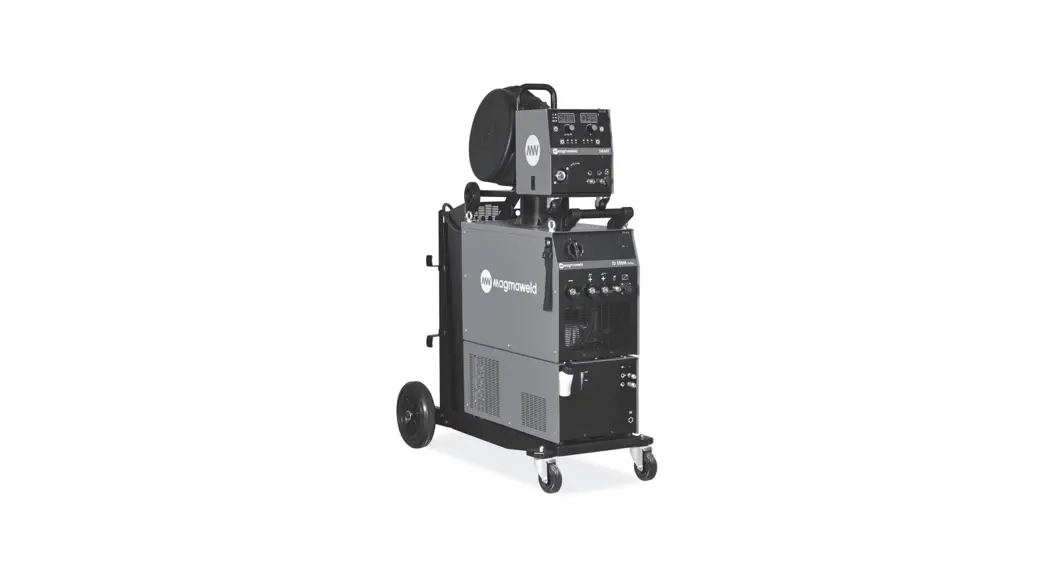
SMART SERIES is an easy-to-use three-phase industrial synergic inverter MIG / MAG welding machine designed for severe conditions with Pulse and no Pulse versions. It provides fast and easy use with its user-friendly interface. It offers excellent welding properties with all solid and cored wires. CC / CV power supply; It allows you to perform MIG, TIG, MMA welding methods and carbon cutting with a single machine. Thanks to its synergic feature, welding current and voltage are adjusted automatically after welding parameters are determined. Its classic and smart modes make it easy for the user to adapt to the synergistic mode.
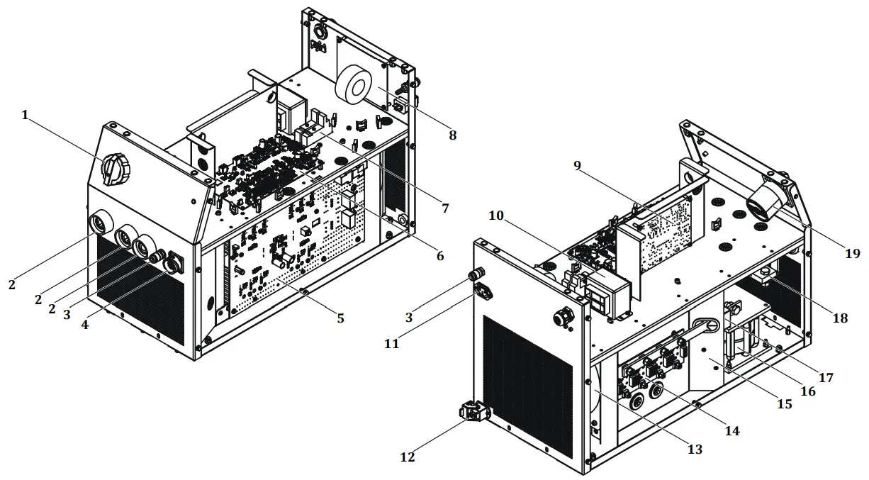
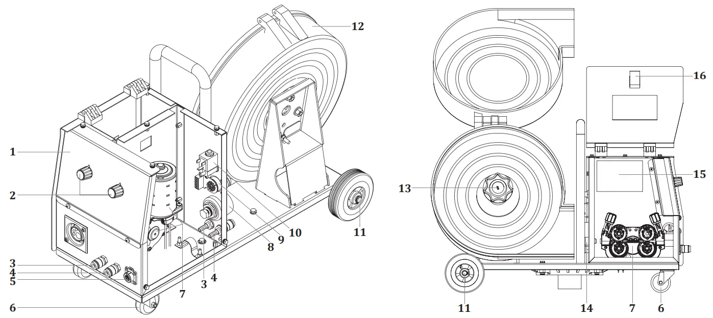
1.2 Machine Components
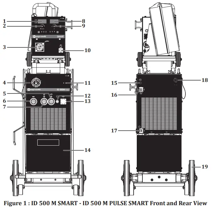
| 1- Left Display 2- Adjustment Pot 3- Torch Connection 4- On / Off Switch 5- Torch Connection 6- Pole Connection 7- Electrode (+) Pole Connection 8- Right Display 9- Adjustment Pot 10- Remote Control Torch Socket | 11- Power LED 12- Gas Output 13- Data Socket 14- Drawer 15- Gas Inlet 16- Heater Socket Socket 17- Water Unit Energy Socket 18- Mains Cable 19- Wheel |
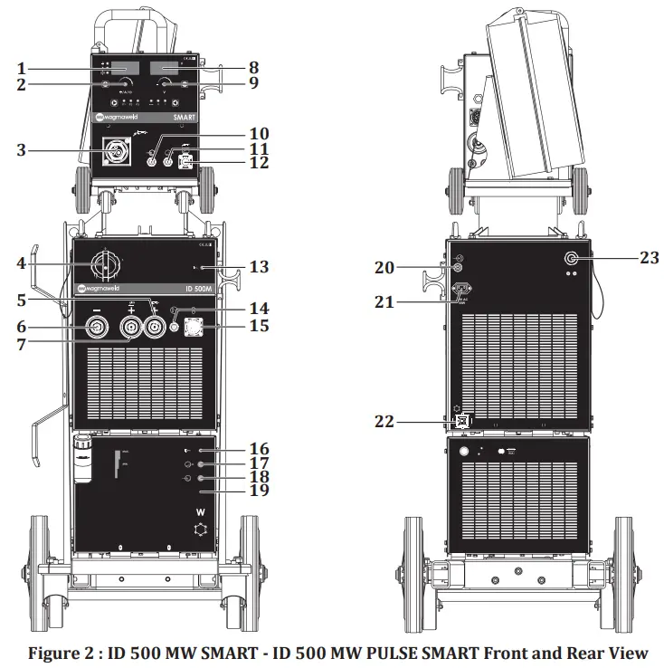
| 1- Left Display 2- Setting Pot 3- Torch Connection 4- On / Off Switch 5- Torch Connection 6- Pole Connection 7- Electrode (+) Pole Connection 8- Right Display 9- Tune Pot 10- Hot Water Inlet 11- Cold Water Outlet 12- Remote Control Torch Socket | 13- Power Led 14- Gas Output 15- Data Socket 16- Water Unit Led 17- Water Unit Hot Water Inlet 18- Water Unit Cold Water Outlet 19- Water Unit 20- Gas Inlet 21- Heater Socket Socket 22- Cooling System Connection 23- Mains Cable |
1.3 Product Label
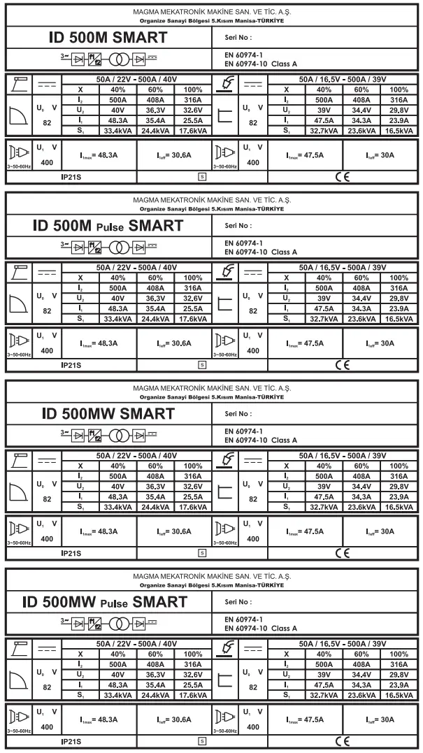
| Three Phase Transformer Rectifier | |
| CC / CV | Constant Current / Constant Voltage |
| Direct Current | |
| MIG/MAG Welding | |
| Mains Input 3-Phase Alternating Current | |
| Suitable for Operation at Hazardous Environments | |
| X | Duty Cycle |
| U0 | Open Circuit Voltage |
| U1 | Mains Voltage and Frequency |
| U2 | Rated Welding Voltage |
| I1 | Rated Mains Current |
| I2 | Rated Welding Current |
| S1 | Rated Power |
| IP21S | Protection Class |
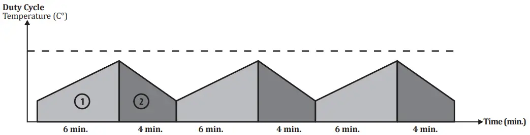
As defined in the standard EN 60974-1, the duty cycle rate includes a time period of 10 minutes.
For example, if a machine specified as 250A at %60 is to be operated at 250A, the machine can weld / cut without interruption in the first 6 minutes of the 10 minutes period (zone 1). However, the following 4 minutes should be kept idle for the machine cool down (zone 2).
1.4 Technical Data
| TECHNICAL DATA | UNIT | ID 500 M/MW SMART ID 500 M/MW PULSE SMART |
| Mains Voltage (3-Phase 50-60 Hz) | V | 400 |
| Rated Power | kVA | 32.7 (%40) |
| Welding Current Range | ADC | 50 – 500 |
| Rated Welding Current | ADC | 500 |
| Open Circuit Voltage | VDC | 82 |
| Dimensions (l x w x h) | mm | 1075 x 531 x 1334 |
| Weight | kg | M : 103.5 MW : 113.5 |
| Protection Class | IP 21 |
1.5 Accessories
| STANDARD ACCESSORIES | QTY | ID 500 M/MW SMART ID 500 M/MW PULSE SMART |
| Workpiece Clamp and Cable | 1 | 7905509505 (95 mm² – 5 m) |
| Gas Hose | 1 | 7907000002 |
| MIG / MAG CO₂ Accessory Set* (Torch + Heater + Regulator) | 1 | 7920000541/7920000551 |
| MIG/MAG Mix/Argon Accessory Set* (Torch + Regulator) | 1 | 7920000545 / 7920000555 |
| * Should be verified during ordering. |
| OPTIONAL ACCESSORIES | QTY | ID 500 M/MW SMART ID 500 M/MW PULSE SMART |
| CO2 Heater | 1 | 7020009003 |
| Gas Regulator (CO2) | 1 | 7020001005 |
| Gas Regulator (Mix) | 1 | 7020001004 |
| Lava MIG 50W Water Cooled MIG Torch (3 m) | 1 | 7120050003 |
| Lava MIG 65W Water Cooled MIG Torch (3 m) | 1 | 7120160003 |
 INSTALLATION
2.1 Delivery Control
Make sure that all the materials you have ordered have been received. If any material is missing or damaged, contact your place of purchase immediately.
The standard box includes the following;
- Welding machine and connected mains cable
- Workpiece clamp and cable
- Gas hose
- Warranty certificate
- User manual
- Welding Wire
In case of a damaged delivery, record a report, take a picture of the damage and report to the transport company together with a photocopy of the delivery note. If the problem persists, contact the customer service.
Symbols and their meanings on the device![]() Welding may be dangerous. Proper working conditions should be ensured and necessary precautions should be taken. Specialists are responsible for the machine and have to be equipped with the necessary equipment and those who are not relevant should be kept away from the welding area.
Welding may be dangerous. Proper working conditions should be ensured and necessary precautions should be taken. Specialists are responsible for the machine and have to be equipped with the necessary equipment and those who are not relevant should be kept away from the welding area.
![]() This device is not compatible with IEC 61000-3-12. If it is desired to connect to the low voltage mains used in homes, it is essential that the installer or the person who will operate the machine to make the electrical connection has information on the machine’s connectivity. In this case the responsibility will be assumed by the person who will perform the installation or by the operator.
This device is not compatible with IEC 61000-3-12. If it is desired to connect to the low voltage mains used in homes, it is essential that the installer or the person who will operate the machine to make the electrical connection has information on the machine’s connectivity. In this case the responsibility will be assumed by the person who will perform the installation or by the operator.![]() The safety symbols and warning notes on the device and in the operating instructions must be observed and the labels must not be removed.
The safety symbols and warning notes on the device and in the operating instructions must be observed and the labels must not be removed.![]() Grids are intended for ventilation. The openings should not be covered in order to provide good cooling and no foreign objects should be inserted.
Grids are intended for ventilation. The openings should not be covered in order to provide good cooling and no foreign objects should be inserted.
2.2 Installation and Operation Recommendations
- Lifting rings or forklifts should be used to move the machine. Do not lift the machine with the gas cylinder. Place the power supply on a hard, level, smooth surface where it will not fall or tip over.
- For a better performance, place the machine at least 30 cm away from the surrounding objects. Pay attention to overheating, dust and moisture near the machine. Do not operate the machine under direct sunlight. If the ambient temperature exceeds 40°C, operate the machine at a lower current or a lower operating cycle.
- Avoid welding outdoors in windy and rainy weather circumstances. If welding is necessary in such cases, protect the welding area and the welding machine with a curtain and canopy.
- When positioning the machine, make sure that materials such as walls, curtains, boards do not prevent easy access to the machine’s controls and connections.
- If you weld indoors, use a suitable fume extraction system. Use breathing apparatus if there is a risk of inhaling welding fumes and gas in confined spaces.
- Observe the operating cycle rates specified on the product label. Suspending operating cycle rates can damage the machine and this may invalidate the warranty.
- The supply cable must comply with the specified fuse value.
- Tighten the ground wire as close as possible to the workpiece. Do not allow the welding current to pass through equipment other than the welding cables such as the machine itself, gas cylinder, chain and roller bearing.
- When the gas cylinder is placed on the machine, secure the gas cylinder by connecting the chain immediately.
If you will not place the gas cylinder on the machine, secure the gas cylinder to the wall with a chain. - The electrical outlet on the back of the machine is for the C02 heater. Never connect a device to the C02 outlet other than the C02 heater !
2.3 Connections
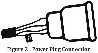
2.3.1 Mains Plug Connection
For your safety, never use the mains cord of the machine without a plug.
- No plug has been connected to the mains cable since there may different types of outlets available in plants, construction sites and workshops. A suitable plug must be connected by a qualified technician. Make sure that the grounding cable marked with
 and a yellow / green color is present.
 - After connecting the plug to the cable, do not attach it to the outlet at this stage.
2.3.2 Connecting the Grounding Clamp to the Workpiece
- Firmly connect the grounding clamp to the workpiece as close as possible to the welding area.
2.3.3 Connecting the Gas Cylinder
- Use regulators and heaters that comply with international standards to work safely and achieve the best results. Make sure the size of the hose connection of the gas regulator you are using is 3/8 .
- Open the gas cylinder valve, keeping your head and face away from the outlet of the valve and keep it open for 5 seconds. By this means, possible sediment and impurities will be discharged.
- If the CO2 heater is to be used, first connect the CO2 heater to the gas cylinder. After connecting the gas regulator to the CO2 heater, insert the plug of the CO2 heater into the CO2 heater outlet on the back of the machine.
- If the CO2 heater will not be used, connect the gas regulator directly to the gas cylinder.
- Connect one end of the tube hose to the gas regulator and tighten the clamp. Connect the other end to the gas inlet at the back of the machine and tighten the nut.
- Open the gas cylinder valve to check that the tube is full and that there are no leaks in the gas flow path.
If you hear a noise and/or detect a smell of gas as a leak indicator, examine your connections and eliminate leakage.
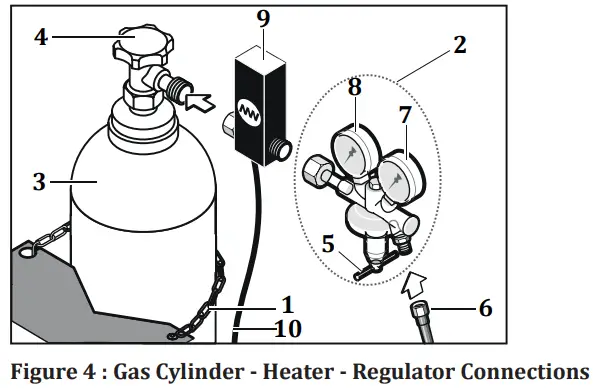
| 1- Chain 2- Gas Regulator 3- Gas Cylinder 4- Gas Cylinder Valve 5- Flow Adjustment Valve | 6- Gas Hose 7- Flow meter 8- Manometer 9- CO2 Heater 10- CO2 Heater Energy Cable |
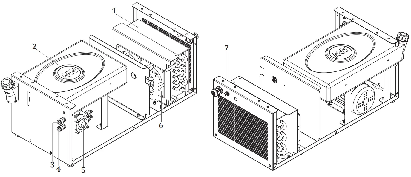
2.3.4 Water Cooling Unit (for MW Models)
- Unit the water cooling unit is used to cool the torch It is a closed circuit system consisting of radiator, fan, pump coolant reservoir.
- Connect the cold (blue) water hose to the cold water outlet on the water cooling system, and the hot (red) water hose to the hot water inlet on the water cooling system.
- Magma weld welding machines come with Magma weld coolant, which is produced to give the best performance. In case of lack of coolant, open the coolant reservoir cap and add Magma weld coolant suitable for the temperature of the working environment. The coolant must be within the minimum and maximum values shown on the front panel of the unit.
- Different coolant or water should not be added. Different liquid additives can cause chemical reactions or different problems.
- Magma weld is not responsible for the risks that may arise in case of adding different liquids. All warranty provisions will be void if different coolant or water is added to the Magma weld coolant.
- If it is desired to use a different brand of coolant, the inside of the coolant tank should be completely empty and there should be no residue or liquid in it.
- It is not suitable to use the water-cooling units with welding machines other than manufactured by Magma Mechatronic Machine vet Sanayi Tricare A.Ş. Water cooling units cannot be operated with external supply.
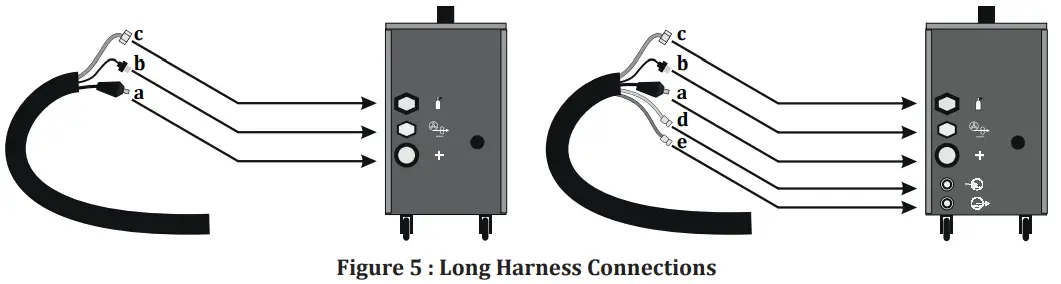
2.3.5 Connection of Interconnection Hose Package
- For easy transport of machines with hose package of 10 meters or longer, the wire feed unit and the interim package have been designed to be detachable. Both ends of the long hose packages are the same and the connections on the machine front must be made with the connectors and sockets on the back of the wire feeder.
- If interconnection hose package is 10 meters or longer, connect the wire feed unit with the hose package as follows.
![]() Dirty and lime (hard) waters reduce the operating life of the torch and the pump.
Dirty and lime (hard) waters reduce the operating life of the torch and the pump.
If the coolant is below the minimum value, there is a possibility of damage and malfunction for the pump and torch.
- There are 2 lads in front of the machine: The power led will light as soon as the machine is activated and the water-cooling unit led will light when the water unit is activated.
- As soon as the machine starts welding, the water circulation will start and after the welding is completed, the water-cooling unit led will remain on during the time set in the menu. In case of any air inlet or problem, the water will not be recirculated.
OPERATION
3.1 Settings in the Bag
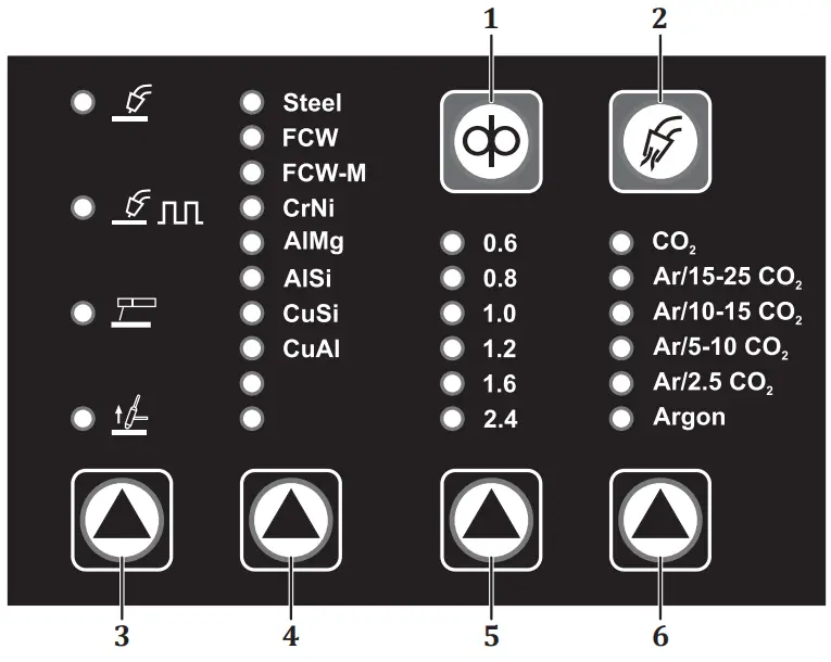
1-) WIRE FEEDING
As long as the button is pressed, the wire is driven and the gas valve does not work. You can use this button to drive the wire into the torch.
2-) GAS FLOW
As long as the button is pressed, gas flow is ensured and wire feed does not work. You can use this button after gas change.
3-) WELDING METHOD SELECTION
Welding method is selected. Each press of the button enables a transition between the lines in the relevant column. When the welding method is selected, the relevant led will light.
Setting Range
 MIG/MAG
 Pulse MIG/MAG
 Pulse welding method is only available in models with pulse. In no pulse( W/O Pulse) models, when this line is reached, the led will not light and Pulse will not be active.
 MMAAccording to the welding method chosen you need to adjust your connections and accessories.
There is a separate outlet for the MMA method in front of the machine. Lift TIGIn Lift TIG welding method, suitable apparatus should be used for torch connector connection.
Thanks to the special apparatus, it will be compatible with the Euro connector.
4-) WIRE TYPE SELECTION
Wire type is selected. The type of wire to be used must be selected correctly. Each press of the button enables a transition between the lines in the relevant column. When the wire type is selected, the corresponding led will light.
Setting Range
| • Steel • FCW • FCW-M • Cr Ni | • Al Mg • Allis • Cu Si • Cu Al |
5-) WIRE DIAMETER SELECTION
Wire diameter is selected. The wire diameter to be used must be selected correctly. Each press of the button enables a transition between the lines in the relevant column. When the wire type is selected, the corresponding led will light.
Setting Range
• 0.6 – 2.4 mm
6-) GAS TYPE SELECTION
Gas type is selected. The type of gas to be used must be selected correctly. Each press of the button enables a transition between the lines in the relevant column. When the wire type is selected, the corresponding led will light.
Setting Range
- CO2
- Ar/15-25 CO2
- Ar/10-15 CO2
- Ar/5-10 CO2
- Ar/2.5 C02
- Argon
3.2 User Interface
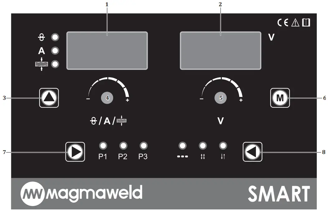
1-) LEFT DISPLAY
It displays the menu content, error messages, wire speed at idle/load time, welding current, thickness value depending on the selected mode. All parameters are displayed on the digital display.
| Idle | Load | |
| Synergic Mode Smart Mode Classic Mode | Welding Set Current Welding Set Current Wire Speed | Welding Current Welding Current Welding Current |
2-) RIGHT DISPLAY
It displays the setting parameters of the functions and the welding voltage at the time of load or idle, depending on the selected mode.
| Idle | Load | |
| Synergic Mode Smart Mode Classic Mode | Welding Set Voltage Welding Set Voltage Welding Set Voltage | Welding Voltage Welding Voltage Welding Voltage |
3-) WELDING MODE SELECTION
Welding mode is selected. Each press of the button enables a transition between the lines in the relevant column. When the welding mode is selected, the relevant led will light.
Setting Range![]() • Classic Mode
• Classic Mode
A • Smart Mode![]() • Synergic Mode
• Synergic Mode
The choice you make from the method tab in the bag creates a differentiation in the welding mode options. When MIG / MAG welding method is selected as the welding method, the modes are as follows:
CLASSIC MODE
When selected, you can adjust your wire speed and welding voltage in certain tolerance value ranges. Wire speed will be adjusted between 1-24 m/min, welding voltage will be adjusted between 15-40 V.
SMART MODE
When selected, welding parameters such as wire type, wire diameter, gas type must be selected correctly.
The machine will automatically adjust the optimum voltage according to the selected welding current. You can adjust the voltage by turning the adjustment knob in the +/- direction within a certain tolerance range.
SYNERGIC MODE
When selected, welding parameters such as wire type, wire diameter, gas type and thickness must be selected correctly. Both the current and the voltage will be automatically adjusted according to the selected welding parameters. The user can navigate both in the current and voltage within a certain tolerance range. The machine will automatically recalculate the voltage according to the current value set at the specified tolerance.
When MMA and Lift TIG welding are selected as welding methods, there is no selection in the mode section.
4-) SETTING POT
Pot (4) is turned right and left for the setting.
- When the MMA welding method is selected, the current is set by the pot.
- When the Lift TIG welding method is selected, the current is set by the pot.
- When the classic mode is selected, the wire speed is set by the pot.
- When the smart mode is selected, the current is set by the pot, the voltage against the adjusted current is automatically calculated.
- When the synergic mode is selected, the thickness of the material to be pot-welded is selected, the voltage is automatically calculated according to the set thickness.
- When you press the menu button (6) and go to the functions section, you need to press the pot once and switch to the other function in order to record in the relevant function.
Example;
When the pre gas (Prep) function is selected; (5) if this value is desired to be saved after setting with the pot (4) it is necessary to press the pot once and switch to the post gas, namely the other function (Pops). If the pot (4) is not pressed and next function (Pops) is not activated, and if you return directly to the main page, there will be no recording.
5-) SETTING POT
Pot (5) is turned right and left for the setting.
- When the classic mode is selected, the voltage value is set.
- When smart mode is selected (4), the voltage is automatically calculated against the current set with the pot. Within certain tolerance range (5) you can set the voltage by turning the pot left and right.
- When synergic mode is selected, voltage is calculated automatically according to set parameters. Within certain tolerance range (5) you can set the voltage by turning the pot left and right.
- When menu button is (6) selected, functions will appear. Pot related functions are set.
6-) FUNCTION SELECTION
When the button (6) is pressed once, functions will appear. To return to the main page, simply press the button again. The selected function (5) is set by turning the pot left or right, when you want to save the selected setting, it is necessary to move to the next function. It is enough to press the pot once to save (4) so, the setting is saved and the next function is activated. The menu section includes the following functions respectively:
 Pre-Gas
Pre-gas time is set.
Setting Range
• 0 – 9.9 sec.
Before starting the welding for the specified time, gas comes in and then the welding starts. It provides protection of the welding pool when the welding starts.
Post-Gas
Post-gas time is set.
Setting Range
• 0 – 9.9 sec.
After the end of the welding for the specified time, gas comes and the welding ends. It provides protection of the welding pool at the end of the welding.
Burn Back
Turnback adjustment is made.
Setting Range
• + 25 – 25
If the value seen on the screen is “+” in backburning, the wire will come forward for the specified time, if the value on the screen is “-”, the wire will continue to burn back for the specified time. When the welding process is completed, it prevents the welding wire from sticking to the contact nozzle.
 Welding Time
When the method is selected, the welding time is set.
Setting Range
• 0.2 – 9.9 son.
 Blank Time
No welding period is set when the method is selected.
Setting Range
• 0.0 – 9.9 sec.
Soft Start
Soft start setting is made.
Setting Range
• On – Off
When starting to weld, the wire speed gradually increases from low speed to the set speed.
In this way, knocks and splashes at the beginning of the welding are prevented.
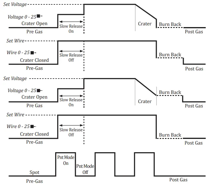
Crater
Crater function setting is made.
Setting Range
• On – Off
It is the filling process to prevent cracks that will occur at the end of welding. When the crater is active, the welding current is reduced with a certain linearity at the end of the
welding and the welding ends.
7-) PROGRAM SELECTION
It is used to record the work done. There are 3 memories. The led of whichever program is processed (7) will burn. To save the program, it is necessary to press the button once and switch to the other program. If you are going to record in the program number 3, it will be enough to press the button once to save your settings after the P3 led is on. Thus, all program lads will be off. After the P3 program, there is an area that allows the program to work without registering. While in this area, the program will not be recorded and the program lads will be off.
Setting Range
• P1 – P2 – P3
😎 TRIGGER MODE SELECTION
Trigger mode selection will be made. Each time the button (8) is pressed, the other trigger mode is switched.
Setting Range
- 2 Trigger
- 4 Trigger
- Method

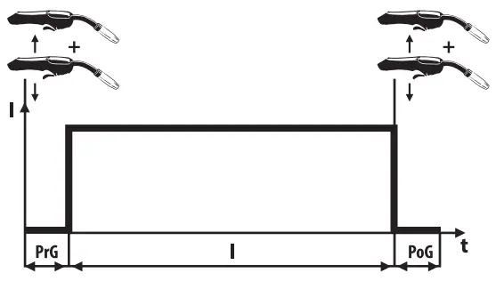
2 TRIGGER MODE : When the torch trigger is pressed, welding starts and the trigger will be held pressed until the welding ends. Releasing the trigger will end the welding.
Welding Start;
- Press and hold the torch trigger.
- Shielding gas flow starts as long as the pre-gas period.
- At the end of the pre-gas period, the wire feed motor runs at a slow speed.
- Welding current increases when the workpiece is reached.
Welding Termination;
- Release the pressed torch trigger.
- The wire feed motor will stop.
- The arc extinguishes after the set burn-back time.
- The process ends after the final gas period.
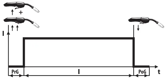
PrG : Initial Gas Time
I : Welding Current
PoG : Final Gas Time
4 TRIGGER MODE : When the torch trigger is pressed and released once, welding starts and there is no need to hold it pressed until the welding ends. Pressing and releasing the trigger again will end the welding process.
Welding Start;
- Press and hold the torch trigger.
- Shielding gas flow starts as long as the pre-gas period.
- At the end of the pre-gas period, the wire feed motor runs at a slow speed.
- Welding current increases when the workpiece is reached.
- Release the pressed torch trigger and the welding will continue.
Welding Termination;
- Release the pressed torch trigger.
- The wire feed motor will stop.
- The arc extinguishes after the set burn-back time.
- The process ends after the final gas period.
PrG : Initial Gas Time
I : Welding Current
PoG : Final Gas Time
METHOD : It is the pant welding to be mentioned in the mode. The welding continues for the specified welding period and ends at the end of the period. No welding will be performed if as long as the defined void period. This period will continue as long as the trigger is not released.
Welding Time : 0.2-9.9 and void time : It is between 0.0 and 9.9 seconds.![]() It should be preferred when the same welding seam and penetration are desired every time. The lengths of the welds made in Method mode will be equal.
It should be preferred when the same welding seam and penetration are desired every time. The lengths of the welds made in Method mode will be equal.
3.3 Remote Control
With a torch with suitable properties and a connector, you can also change your welding current (wire speed) /welding voltage through the torch without going near your machine. Connect the remote control torch socket. Socket connections are as follows :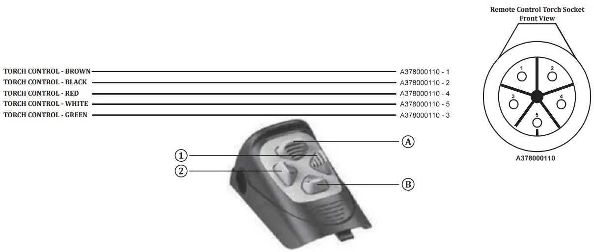
| Mode | Button | Position |
| Classic Mode | 1 | You can reduce your wire speed to the minimum tolerance value (-10%). Setting Range : 0.5 m/min |
| 2 | You can increase your wire speed up to the maximum tolerance value (+10%). Setting Range : U.S m/min | |
| A | You can increase your welding voltage up to the maximum tolerance value (+10%). Setting Range : U.S V | |
| B | You can reduce your welding voltage up to the minimum tolerance value (-10). Setting Range : 0.5 V | |
| Smart Mode | 1 | You can reduce your welding current to the minimum tolerance value (-10%). Setting Range : 5 A |
| 2 | You can increase your welding current up to the maximum tolerance value (+10%). Setting Range : 5 A | |
| A | You can increase your welding voltage up to the maximum tolerance value (+ 10%). Setting Range : 0.5 V | |
| B | You can reduce your welding voltage to the minimum tolerance value (-10%). Setting Range : 0.5 V | |
| Synergic Mode | 1 | You can reduce your welding current to the minimum tolerance value (-10%). Setting Range : 5 A |
| 2 | You can increase your welding current up to the maximum tolerance value (+10%). Setting Range : 5 A | |
| A | You can increase your welding voltage up to the maximum tolerance value (+10%). Setting Range : U.S V | |
| B | You can reduce your welding voltage to the minimum tolerance value (-10%). Setting Range : 0.5 V |
3.4 Arc Length Adjustment (Arc)
When you press and hold the adjustment knob for 3 seconds, the arc length function will be active. The factory setting is 0.0. You can change the arc length adjustment in the range of + 7 / -7 by turning the same knob to the right or left. As it goes towards +7, the wire approaches the nozzle, the arc length increases. As it goes towards -7, the wire approaches the welding metal and the arc length decreases. After the desired setting is made, the setting is exited by pressing the same knob.
3.5 MIG Curve
| Parameter | Value Range | Factory Setting | 2- Position MIG | 4- Position MIG | ||
| Pre-Gas | 0,0 – 9,9 sec | 0,1 sec | ||||
| Post Gas | 0,0 – 9,9 sec | 0,1 sec | ✓ | ✓ | ||
| Burn Back | 25 – 0 – 25 | 0 step | ✓ | ✓ | ||
| Arc On Time | 0,2 – 9,9 sec | 0,2 sec | ✓ | ✓ | ||
| Arc Off Time | 0,0 – 9,9 sec | 0,0 sec | ✓ | ✓ | ||
| Wire Diameter | 0,6 – 2,4 mm | 1,0 mm | ✓ | ✓ | ||
| Thickness | 0,6 – 20,0 mm | 1,0 mm | ✓ | ✓ | ||
| Gas Type | CO2, Ar/5-10 CO2, Ar/15-25 CO2, Ar/2.5 CO2, Ar/10-15 CO2, Argon | |||||
| Wire Type | Steel, A1Mg, FCW, Alsip, FCW-M, Cusic, Carin, Cal | |||||
| Crater | Active / Passive | Passive | ✓ | ✓ | ||
| Mode | Synergic / Smart / Classic | |||||
| Trigger | Method / 2 / 4 | 2 | ✓ | ✓ | ||
| Method | MIG/MAG – MMA – LIFT TIG | MIG / MAG | ||||
3.6 Connection to Mains![]() Depending on the selected Mode, welding set current adjustment will be done with the help of the pot. The setting will be performed by turning the pot left or right.
Depending on the selected Mode, welding set current adjustment will be done with the help of the pot. The setting will be performed by turning the pot left or right.
![]() Connect the poles according to the type of the welding process.
Connect the poles according to the type of the welding process.
- Start the machine with the on/off switch.
- Turn the machine off by turning the on / off switch back to off after hearing the fan noise and seeing the mains lamp is illuminated.
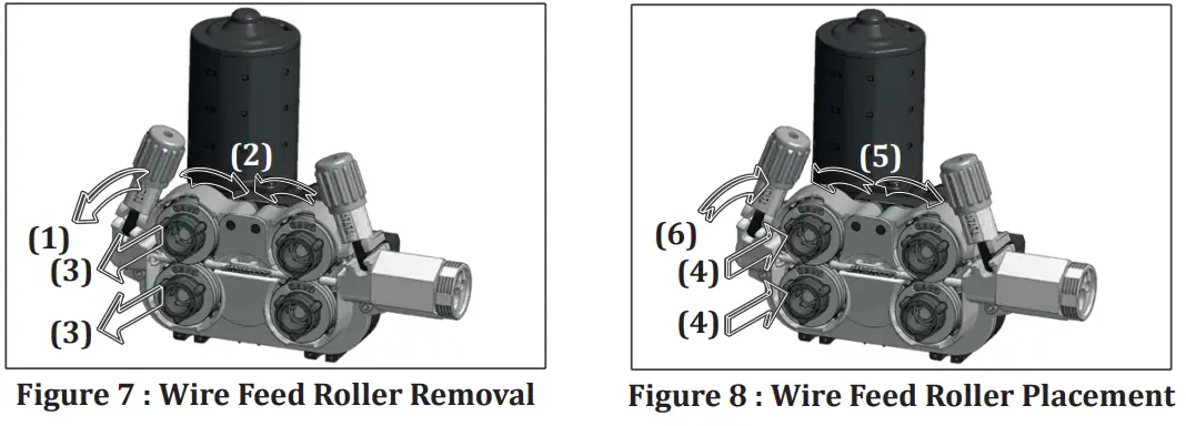
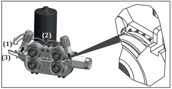
3.7 Selection and Replacement of Wire Feed Rollers
- When you open the cover of the wire feeding section, you can adjust the free gas and wire with the button on the side. You will see the four-roller wire feeding system with an encoder structure. Thanks to its 4 WD system structure, the wire is mechanically driven with the power applied to the four rollers. Even in negativities such as motor heating and increased friction, the wire feed speed will not change, provides excellent arc stability. As soon as the machine is energized, the led inside of the compartment will be active which will make it easier to replace the roller.
 Figure 6 : Wire Feed System
a- Motor
b- Euro Connector
c- Pressure Adjustment Screw
d- Top Wire Feed Rollers
e- Bottom Wire Feed Reels
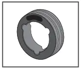
f- Wire Feed Rollers Locking Mechanism - Use wire feed rollers suitable for the material and diameter of the welding wire you will use. Use V-grooved wire feed rollers for steel and stainless steel, V-grooves type for cored wires and U-grooves type for aluminum.
- If you need to replace the wire feed rollers, pull the pressure adjustment screw toward your side and after lifting the roller covers, remove the existing rollers.

- You must unlock the rollers before you can remove them. By reverse-turning the locking direction, the cavities inside the wire feed roller must be overlapped with the protrusions on the wire feed body in order to unlock the lock.

- Both sides of the rollers are marked according to the wire diameter used.
- Place the rollers on the flange so that the wire diameter value you will use will be on the side facing your side.
- Place the roller to be used so that the cavities inside the wire feed roller overlap the protrusions on the wire feed body. Turn to the right or left to ensure that the locking sound is heard and that the wire feed rollers are in place. Then lower the pressure rollers and lift the pressure roll lever to lock it onto the pressure roller.

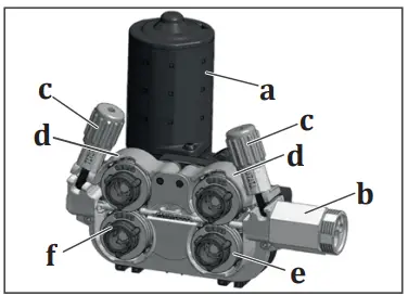 Figure 6 : Wire Feed System
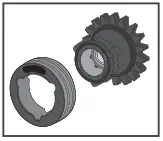
3.8 Placing The Wire Spool And Wire Feeding Process
- Unscrew the screw of the wire transport system by turning it. Slide the welding wire roller onto the wire carrier system shaft and re-tighten the screw.
 Figure 9 : Placement of Wire SpoolTightening the screw of the wire transport system prevents the wire from being fed and may cause failures. If the screw has not been tightened adequately this can cause the wire spool to empty after a period of time when the wire feed has stopped. For this reason, do not connect the screw too tightly or too loosely.
- Pull and lower the pressure screw on the wire feed roller, which means bring the pressure rollers to idle position.
- Find and open the welding wire end from the wire spool and cut off the end with a side chisel.If the end of the wire is missed, the wire can jump like a spring and damage you and others.
- Pass the wire through the wire entry slot without releasing the wire into the rollers and into the torch through the rollers.

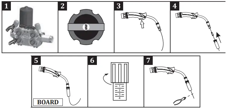
Figure 10 : Feeding the Wire to Rollers - Pull the pressure adjustment screws towards you and release the pressure on the rollers1 .
- Turn the on/off switch to position “1” to start the machine2 .
- Remove the nozzle and the contact nozzle and press the trigger until the wire comes out from the tip of the torch, while observing that the welding wire roller rotates freely then push and release the trigger a few times to check for any loosening of the winding3 .
- Re-attach the nozzle and contact nozzle to the torch when the wire comes out from the tip of the torch4 .
- Drive the wire on a non-insulating material 5 such as wood and make the appropriate wire pressure adjustment6 and cut the tip of the wire7.
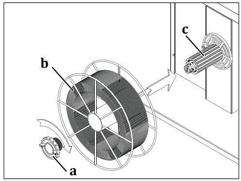 Figure 9 : Placement of Wire Spool
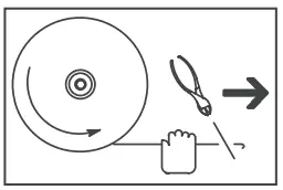
![]() The following effects will occur if the pressure adjustment screw is overtightened, left loose or if the wrong wire feed roller is used.
The following effects will occur if the pressure adjustment screw is overtightened, left loose or if the wrong wire feed roller is used.
A: Suitable wire pressure and conduit dimensions.
B: The wire is distorted since the pressure lever is too tight.
C: The roller surface is deteriorated due to excessive pressure on the pressure lever.
D: The conduit length of the roller is small for the wire used. Wire form is distorted.
E: The conduit length of the roller is big for the wire used. The wire cannot be transmitted to the welding area.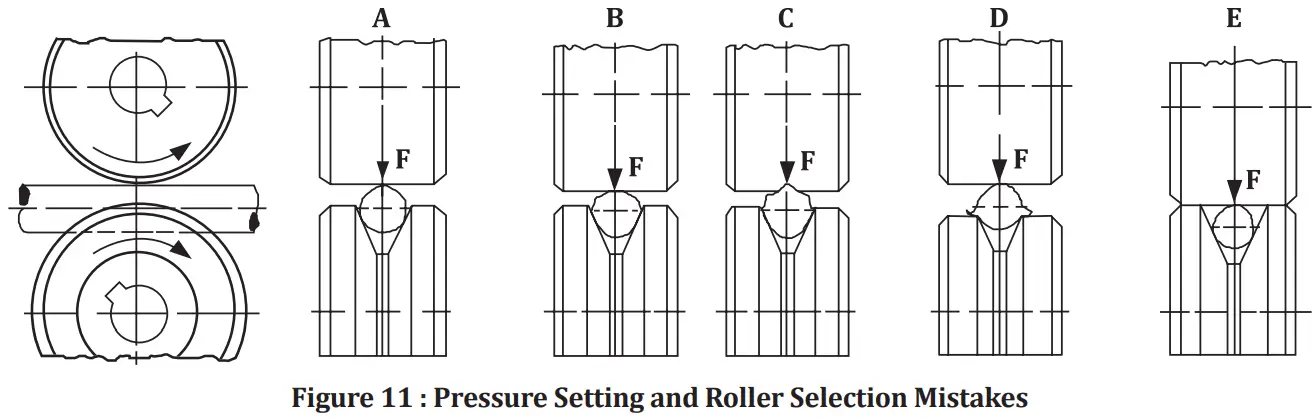
3.9 Adjustment of Gas Flow![]() Make the gas adjustment and gas test by lifting the wire feed roller pressure lever!
Make the gas adjustment and gas test by lifting the wire feed roller pressure lever!
- Adjust the gas flow with the flow control valve.
- Practical gas flow rate (CO₂, Ar, mixture) is 10 times of wire diameter.
For example, if the wire diameter is 0.9 mm, the gas flow rate can be adjusted as 10 x 0.9 = 9 l / min. - You can use the table on the side for more precise flow adjustment.
- After adjusting the gas flow, lift the thrust bearing arm and close the wire feed unit door.
| Mild Steel and Metal Cored | Flux Cored | Stainless Steel | Aluminium | ||
| Diameter (mm) | 0.8 | 8 lt/min. | 7 lt/min. | 8 lt/min. | 8 lt/min. |
| 0.9 | 9 lt/min. | 8 lt/min. | 9 lt/min. | 9 lt/min. | |
| 1 | 10 lt/min. | 9 lt/min. | 10 lt/min. | 10 lt/min. | |
| 1.2 | 12 lt/min. | 11 lt/min. | 12 lt/min. | 12 lt/min. |
3.10 Machine Features
CC / CV Construction
- Allows MIG, MMA and TIG welding.
Memory
- There are 3 job memories that can be saved.
Variety of Usage Functions
- It provides a user-friendly operation with its classic, smart and synergistic MIG / MAG modes.
Soft Start
- Prevents the formation of knocked and jerky start by increasing the wire speed gradually.
Smart Performance
- Thanks to the intelligent performance control, the welding parameters of the machine are continuously monitored and analyzed.
- If compulsory conditions occur, the machine switches to the protection mode in order to extend its life and protect itself against malfunctions.
- This protection is indicated by a thermal led warning on the machine panel.
- The machine is reactivated after 2 minutes of safe time.
Smart Fan
- The internal temperature of the machine is continuously measured. The cooling fan speed is increased or decreased according to the measured temperature. When the temperature is below a certain degree, the phase will be stopped completely. The amount of dust entering the machine is reduced by this function. As the machine life is prolonged, energy will be saved. The fan provides continuous cooling performance during welding.
Current/Voltage Control over the Torch
- With the control connection option, you can also change your welding current / welding voltage through the torch without going near your machine.
Robot Compatibility
- Provides ease of use with its robot compatible structure.
Magnet Compatibility
- Source and media information is stored in real time form thanks to its mag NET-ready structure. Some values can be read on the LCD panel on the machine front, while other information (Original Equipment Activity-OEE, Welding Parameters-WR, Quality, etc.) can be stored and monitored or reported on the mag NET platform. (Optional)
Operation with generators
- Suitable for operation with generators. The kVA operating value should be determined by referring to the technical specifications.
Protection
- Protected against missing or incorrect phase.
Voltage Protection
- If the mains voltage is too high or too low, the machine automatically protects itself by giving an error code on the display. By this means, no damage is caused to the machine components and long life of the machine is ensured. After the ambient conditions have returned to normal, the machine functions will also be activated.
 MAINTENANCE AND SERVICE
- Maintenance and repairs to the machine must be carried out by a qualified personnel. Our company will not be responsible for any accidents that may occur by unauthorized interventions.
- Parts that will be used during repair can be obtained from our authorized services. The use of original spare parts will extend the life of your machine and prevent performance losses.
- Always contact the manufacturer or an authorized service designated by the manufacturer.
- Never make interventions yourself. In this case the manufacturer warranty is no linger valid.
- Always comply with the applicable safety regulations during maintenance and repair.
- Before performing any work on the machine for repair, disconnect the machine’s power plug from the power supply and wait for 10 seconds for the capacitors to discharge.
4.1 Maintenance![]() Every 3 Months
Every 3 Months
- Do not remove the warning labels on the device. Replace the worn/torn labels with the new ones. Labels can be obtained from the authorized service.
- Check your torch, clamps and cables. Pay attention to the connections and the durableness of the parts. Replace the damaged/defective parts with the new ones.
Do not ever make additions to/repair the cables.
- Ensure adequate space for ventilation.
- Before starting welding, check the gas flow rate from the tip of the torch with a flow meter. If the gas flow is high or low, bring it to the appropriate level for the welding
process.
![]() Every 6 Months
Every 6 Months
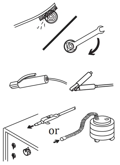
- Clean and tighten fasteners such as bolts and nuts.
- Check the lead of the electrode pliers and earth pliers.

- Open the side covers of the machine and clean with low pressure dry air. Do not apply compressed air to electronic components at close range.
- Periodically replace the water in the tank of the water cooling unit with fresh, hard water and protect it against freezing with antifreeze.
NOTE: The above mentioned periods are the maximum ones that should be applied if no problems are encountered in your device. Depending on the work load and contamination of your work environment, you can repeat the above processes more frequently.![]() Never operate the machine when covers are open.
Never operate the machine when covers are open.
4.2 Non-Periodic Maintenance
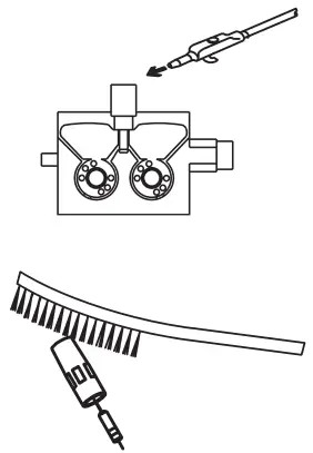
- The Wire Feeding Mechanism must be kept clean and the roller surfaces must not be lubricated.
- Always remove any deposits on the mechanism with dry air each time you replace a welding wire.

- The consumables on the torch should be cleaned regularly. It should be replaced if necessary. Make sure that these materials are original products for long-term use.
4.3 Troubleshooting
The following tables contain possible errors to be encountered and their solutions.
| Failure | Reason | Solution |
| Machine is not operating | • The machine is not connected to the mains, or the plug is not connected | • Make sure that the machine is plugged in |
| • The mains connections are not correct | • Check whether the mains connections are correct | |
| • The power supply fuses, mains cable or plug are problematic | • Check the power supply fuses, mains cable and plug | |
| • The fuse has blown | • Check the fuse | |
| • Contactor failure | • Check the contactor | |
| Wire feed motor failure | • The fuse has blown | • Check the fuse |
| • Electronic card failure | • Contact the authorized service | |
| The wire feed motor is operating, but the wire is not moving further | • Wire feed rollers were not chosen to fit the wire diameter | • Select the appropriate wire feed roller |
| • The pressure on the wire feed rollers is too minimal | • Adjust the pressure roller | |
| Welding quality is not good | • There is a problem in the connection of grounding clamps of the machine | • Make sure that the grounding clamps of the machine is connected to the workpiece |
| • Cables and connection points are worn out | • Make sure that the cables are secure and that the connection points are not worn | |
| • Parameter and process selection are not correct | • Make sure that the parameter and process selection are correct. Follow the steps below according to the process you have selected | |
| • Gas flow is not open oar faulty | • Check that the gas flow is open, ensuring that the flow is correct | |
| • Welding torch is damaged | • Make sure the welding torch is secure | |
| • Consumables were selected incorrectly or damaged | • Appropriate consumables should be selected and the consumables on the torch must be cleaned regularly. Improperly selected or worn consumables should be replaced | |
| • The pressure adjustment of the rollers is not correct | • Pressure roller settings must be made correctly |
| Failure | ‘ Reason | ‘ Solution |
| Fan is not operating | •The fuse has blown | • Check the fuse |
| •Fan motor failure | • Contact the authorized service | |
| Machine operates noisily | • Contactor failure | • Contact the authorized service |
| Unstable and / or non-adjustable welding current | • Diode group failure | • Contact the authorized service |
| Heater outlet is not operating | • The fuse has blown | • Check the fuse. Contact the authorized service |
| The value 0000 / 110P will be displayed on the screen | • The welding parameters have not been selected appropriately | • All parameters such as wire type, gas type, etc. must be selected according to your welding method |
4.4 Error Codes
| Error Code | Error | Cause | Solution |
| E01 | Communication Error | • There may be problems at different points in the machine | |
| •Contact the authorized service | |||
| k 02 | Thermal Protection | • The machine’s run time rate may have been exceeded | • Wait for a while to allow the machine to cool down. If the failure disappears, try to run the machine at lower amperage values |
| • Fan may not be operating | • Visually inspect the fan for proper operation. Please contact the authorized service if it does not operate | ||
| • The air inlet and outlet ducts may have been blocked • The machine operating environment can be extremely hot or lack of air | • Open the air ducts • Ensure that the machine is placed in an area where it can work operate comfortably | ||
| I:)3 | Overcurrent Failure | • The machine may have been overloaded | • Contact the authorized service |
| • There may be problems at different points in the machine | • Contact the authorized service | ||
| F0,1 | Low mains voltage | • Mains voltage may have decreased | • Check the mains connection cables and voltage. Make sure that the correct voltage input is provided. If the mains voltage is normal, contact the authorized service |
| 0.00E+00 | Temperature Sensor Reading Failure | • Temperature sensor may have failed or there may be an electrical connection problem | • Contact the authorized service |
| T0c) | High mains voltage | • Mains voltage may have increased | • Check the mains connection cables and voltage. Make sure that the correct voltage input is provided. If the mains voltage is normal, contact the authorized service |
![]() ANNEX
ANNEX
5.1 Spare Parts Lists Power Source Spare Parts List
| NO | DEFINITION | MATERIAL CODE |
| 1 | Switch Button | A308900004 |
| 2 | Welding Plug | A377900106 |
| 3 | Quick Coupling | A245700004 |
| 4 | Connector | A378020009 |
| 5 | Electronic Card E206A-1 | K405000280 |
| 6 | Electronic Card E206A CNT3P | K405000324 |
| 7 | Relay Socket | A312900020 |
| 8 | Electronic Card E202A-FLT4 | K405000254 |
| 9 | Electronic Card E121A-2 | K405000230 |
| 10 | Control Transformer | K366100006 |
| 11 | Power Connector | A378000050 |
| 12 | Connector (Complete) | A378002002 |
| 13 | Fan Monophasic | A250200019 |
| 14 | Electronic Card E202A-4A | K405000255 |
| 15 | Electronic Card E206A FLT | K405000251 |
| 16 | Shock Coil | A421050002 |
| 17 | Hall Effect Sensor | A834000003 |
| 18 | Shunt | A833000005 |
| 19 | Paco Switch | A308033102 |
| Relay | A312100012 | |
| Relay | A312100018 |
Wire Feeder Spare Parts List
| NO | DEFINITION | MATERIAL CODE |
| 1 | Panel Label | K109900158 |
| 2 | Pota’s Button | A229500005 |
| 3 | Quick Coupling Red | A245700003 |
| 4 | Quick Coupling Blue | A245700002 |
| 5 | Connector | A378000103 |
| 6 | Sheet Metal Swivel Wheel | A225100014 |
| 7 | Processed Wire Feed System | K309003213 |
| 8 | Welding Plug | A377900011 |
| 9 | Electronic Card | K405000234 |
| 10 | Gas Valve | A253006019 |
| 11 | Plastic Wheel | A225222002 |
| 12 | Wire Basket Housing (Plastic) | A229900101 |
| 13 | Wire Carr. Mac. System 3-Way Connection | A229900003 |
| 14 | Wire Feed Guide Slot | K107909065 |
| 15 | Membrane Label | K109900158 |
| 16 | Cover Lock | A229300006 |
| Electronic Card | K405000325 | |
| Electronic Card | K405000326 |
Water Cooling Unit Spare Parts List
| NO | DEFINITION | MATERIAL CODE |
| 1 | Radiator | A260000004 |
| 2 | Water Tank | A249000005 |
| 3 | Quick Coupling Blue | A245700003 |
| 4 | Quick Coupling Red | A245700002 |
| 5 | Water Pump | A240000006 |
| 6 | Fan | A250001126 |
| 7 | Glass Fuse Holder | A300190001 |
| Glass Fuse Fast | A300101011 |
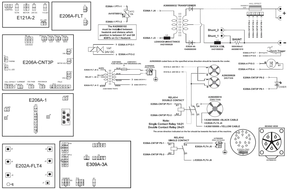
5.2 Circuit Diagrams
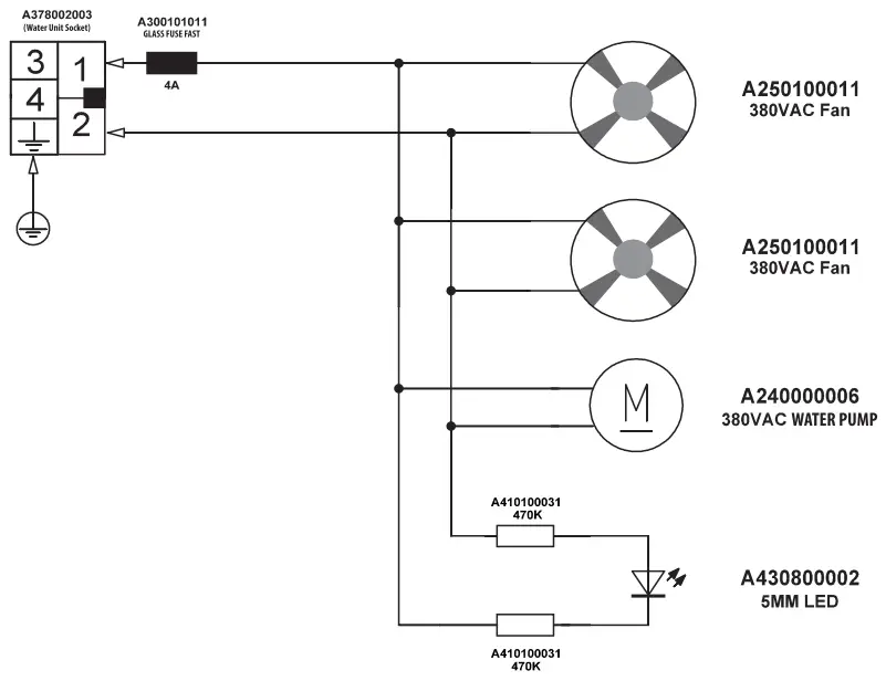
Water Unit Circuit Diagram
Magma Mechatronic Machine Sanayi vet Ti caret A.Ş.
Organize Sanayi Bilges, 5. Kasim 45030 Manias, TÜRKİYE
T: (236) 226 27 00
F: (236) 226 27 28
22.12.2021
UM_IDMMWPS500_022021_122021_002_164![]() (+90) 444 93 53
(+90) 444 93 53
magmaweld.com
[email protected]


