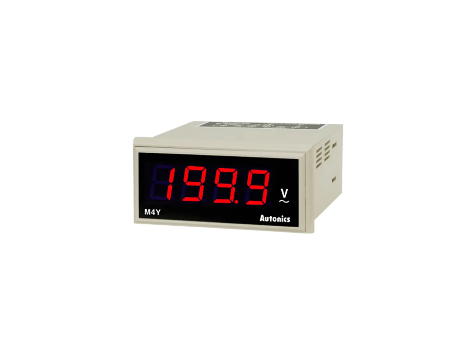
Autonics M4Y Series Panel Meters
For your safety, read and follow the considerations written in the instruction manual, other manuals and Autonics website.
The specifications, dimensions, etc. are subject to change without notice for product improvement. Some models may be discontinued without notice.
Features
- Max. display value: 1999
- Auto-zero function and hold display value function
- Linear display based on input specification
- Display output values (0 – 10 VDCᜡ) from power converters (options available for DC 4 – 20 mA, 1 – 5 VDCᜡ)
- RMS or AVG value selection (AC voltage)
- 7-segment LED display
- DIN standard size models
Safety Considerations
- Observe all ‘Safety Considerations’ for safe and proper operation to avoid hazards.
 symbol indicates caution due to special circumstances in which hazards may occur.
![]() Warning Failure to follow instructions may result in serious injury or death.
Warning Failure to follow instructions may result in serious injury or death.
- Fail-safe device must be installed when using the unit with machinery that may cause serious injury or substantial economic loss. (e.g. nuclear power control, medical equipment, ships, vehicles, railways, aircraft, combustion apparatus, safety equipment, crime / disaster prevention devices, etc.)
Failure to follow this instruction may result in personal injury, economic loss or fire. - Do not use the unit in the place where flammable / explosive / corrosive gas, high humidity, direct sunlight, radiant heat, vibration, impact or salinity may be present.
Failure to follow this instruction may result in explosion or fire. - Install on a device panel to use.
Failure to follow this instruction may result in fire or electric shock. - Do not connect, repair, or inspect the unit while connected to a power source.
Failure to follow this instruction may result in fire or electric shock. - Check ‘Connections’ before wiring.
Failure to follow this instruction may result in fire. - Do not disassemble or modify the unit.
Failure to follow this instruction may result in fire or electric shock.
![]() Caution Failure to follow instructions may result in injury or product damage.
Caution Failure to follow instructions may result in injury or product damage.
- When connecting the power / measurement input and relay output, use AWG 24 (0.20 mm2 ) to AWG 15 (1.65 mm2 ) cable or over and tighten the terminal screw with a tightening torque of 0.98 to 1.18 N m.
Failure to follow this instruction may result in fire or malfunction due to contact failure. - Use the unit within the rated specifications.
Failure to follow this instruction may result in fire or product damage. - Use a dry cloth to clean the unit, and do not use water or organic solvent.
Failure to follow this instruction may result in fire or electric shock. - Keep the product away from metal chip, dust, and wire residue which flow into the unit.
Failure to follow this instruction may result in fire or product damage.
Cautions during Use
- Follow instructions in ‘Cautions during Use’.
Otherwise, It may cause unexpected accidents. - Power supply should be insulated and limited voltage / current or Class 2, SELV power supply device.
- Install a power switch or circuit breaker in the easily accessible place for supplying or disconnecting the power.
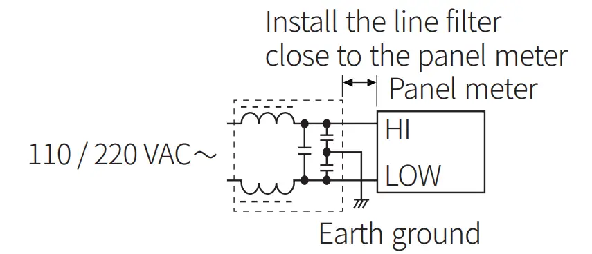
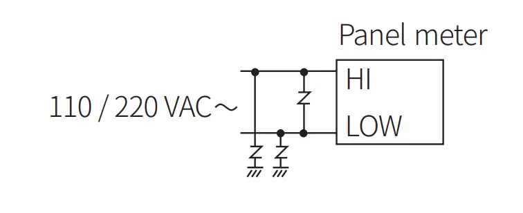
- Keep away from high voltage lines or power lines to prevent inductive noise. In case installing power line and input signal line closely, use line filter or varistor at power line and shielded wire at input signal line.
Do not use near the equipment which generates strong magnetic force or high frequency noise.
Connection with the line filter
Connection with the varistor
- This unit may be used in the following environments.
- Indoors (in the environment condition rated in ‘Specifications’)
- Altitude max. 2,000 m
- Pollution degree 2
- Installation category II
Ordering Information
This is only for reference, the actual product does not support all combinations.
For selecting the specified model, follow the Autonics webstie.

❶ Input type
DV: DC voltage
AV: AC voltage
DA: DC current
AA: AC current
W: Power
T: Rotation
S: Speed
DI: Scaling (DC 4 – 20 mA)
❷ AC measurement method
No mark: AVG
R: RMS
❸ Measurement input
Refer to measurement input specifications
Measurement Input Specifications
| Measurement input | Input type | |||||||
| DV | AV | DA | AA | W 01) | T 02) | S 02) | DI | |
| No mark | – | – | – | – | – | – | – | 1999 |
| 1 | 199.9 mVDC | 199.9 mVAC | 199.9 ㎂ | 19.99 mA | 199.9 W | 1999 rpm | 1999 m / min | – |
| 0 – 10 VDC | 0 – 10 VDC | |||||||
| 2 | 1.999 VDC | 1.999 VAC | 1.999 mA | 199.9 mA | 1.999 kW | 1999 rpm | 1999 m / min | – |
| 0 – 10 VAC | 0 – 10 VAC | |||||||
| 3 | 19.99 VDC | 19.99 VAC | 19.99 mA | 1.999 A | 19.99 kW | – | – | – |
| 4 | 199.9 VDC | 199.9 VAC | 199.9 mA | 19.99 A | 199.9 kW | – | – | – |
| 5 | 300 VDC | – | 1.999 A | 199.9 A | – | – | – | – |
| 6 | – | 400 VAC | 19.99 A | 1999 A | – | – | – | – |
| 7 | – | – | 199.9 A | – | – | – | – | – |
| 8 | – | – | 1999 A | – | – | – | – | – |
| DX | – | – | – | – | – | DC input option | – | |
| AX | – | – | – | – | – | AC input option | – | |
| XX | Option | Option | Option | Option | Option | – | – | Option |
- This specification is based on the transducer with 0 – 10 VDC
 output. When the output of transducer is DC 4 – 20 mA or 1 – 5 VDC, use the scaling meter.
 - This specification is based on the tacho generator with 0 – 10 VDC or 0 – 10 VAC output.
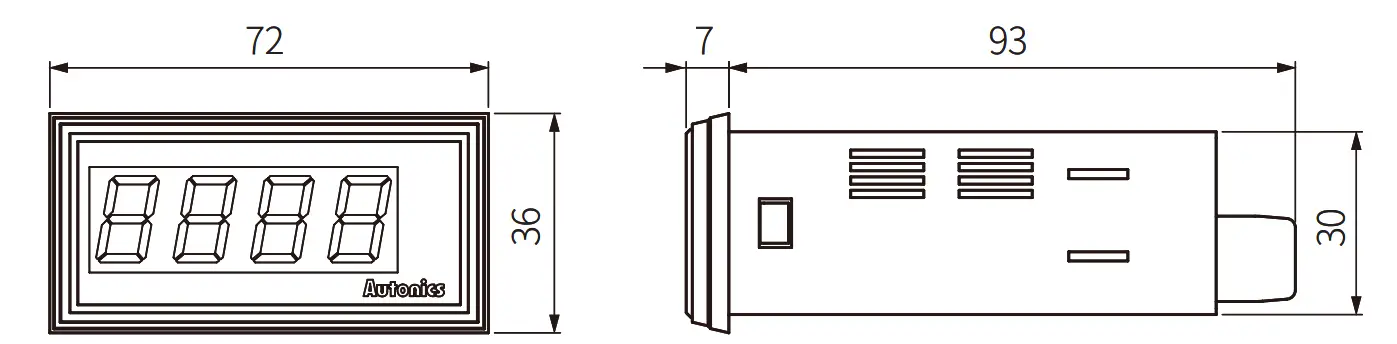
Dimensions
- Unit: mm, For the detailed drawings, follow the Autonics website.

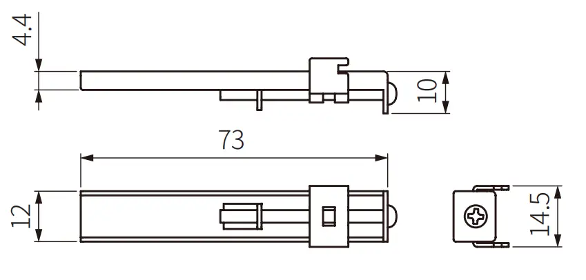
- Bracket

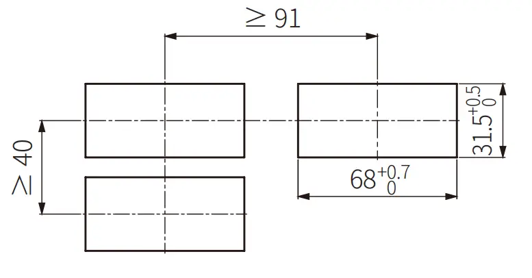
- Panel cut-out

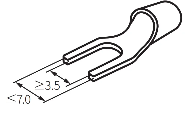
Cautions during Wiring
- Unit: mm, Use terminals of size specified below.

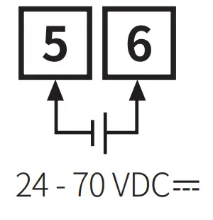
Connections
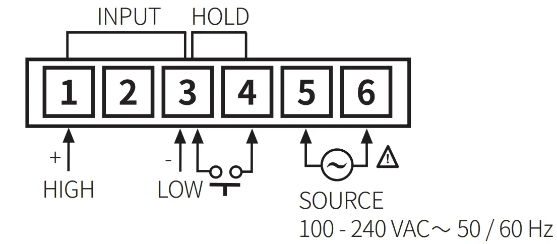
- Power option

Product Components
- Product
- Bracket × 2
- Instruction manual
Specifications
| Input type | DC voltage | AC voltage | DC current | AC current | Power | Rotation, speed | Scaling |
| Max. allowable input | ≤ 300 VDC | ≤ 400 VAC | ≤ DC 2 A | ≤ AC 5 A | ≤ 10 VDC | ≤ 10 VDC | DC 4 – 20 mA |
| ≈ 150 % F.S. for each measured input range 01) | |||||||
| Display method | 7-segment (red) LED (character height: 14 mm) | ||||||
| Display accuracy | Dependent on the input type | ||||||
| DC input | ± 0.2 % F.S. rdg ± 1-digit | ||||||
| AC input | ± 0.5 % F.S. rdg ± 1-digit | ||||||
| Display scale | 1999 | ||||||
| Sampling time | 2.5 times / sec | ||||||
| Response speed | ≈ 2 sec (0 to 1999) | ||||||
| Sampling cycle | 300 ms | ||||||
| Operation method | Dual integral method | ||||||
| Unit weight | ≈ 144 g | ||||||
| Approval | |||||||
01) At 400 VAC![]() input: ≈ 120 % F.S. for each measured input range
input: ≈ 120 % F.S. for each measured input range
| Power supply 01) | 100 – 240 VAC |
| Power consumption | Dependent on the input type |
| DC input | 2 W |
| AC input | 4 VA |
| Insulation resistance | ≥ 100 MΩ (500 VDC |
| Dielectric strength | 2,000 VAC |
| Noise immunity | ± 1 kV square wave noise (pulse width: 1 ㎲) by the noise simulator |
| Vibration | 0.75 mm double amplitude at frequency of 10 to 55 Hz (for 1 minute) in each X, Y, Z direction for 1 hours Vibration (malfunction) 0.5 mm double amplitude at frequency of 10 to 55 Hz (for 1 minute) in each X, Y, Z direction for 10 min |
| Shock | 300 m/s2 (≈ 30 G) in each X, Y, Z direction for 3 times |
| Shock (malfunction) | 100 m/s2 (≈ 10 G) in each X, Y, Z direction for 3 times |
| Ambient temperature | -10 to 50 ℃, storage: -25 to 65 ℃ (no freezing or condensation) |
| Ambient humidity | 35 to 85 %RH, storage: 35 to 85 %RH (no freezing or condensation) |
01) Power supply 24 – 70 VDC ![]() option is also available to order.
option is also available to order.
Error
- When 1999 or -1999 flashes with a certain measurement input, disconnect power supply and then check the cables.
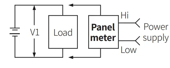
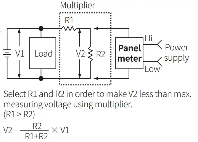
Connections of Applications
DC voltmeter connection
- V1 (measuring voltage): ≤ 300 VDC

- V1 (measuring voltage): ≥ 300 VDC

AC voltmeter connection
- AC voltmeter connection
- V1 (measuring voltage): ≥ 400 VAC
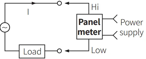
DC ammeter connection
- I (measuring current): ≤ DC 2 A

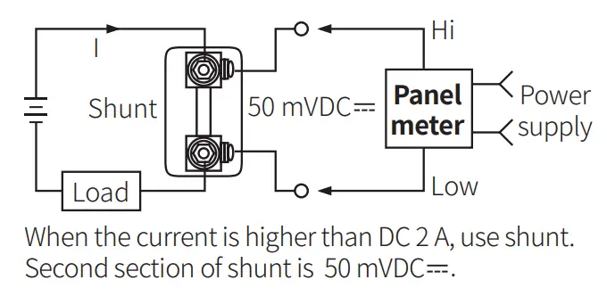
- I (measuring current): ≥ DC 2 A

AC ammeter connection
- I (measuring current): ≤ AC 5 A
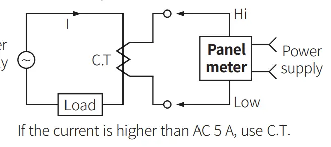
- I (measuring current): ≥ AC 5 A

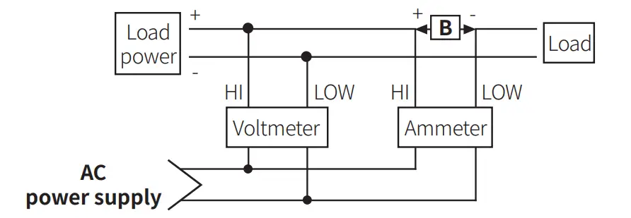
Simultaneous connection of voltmeter and ammeter
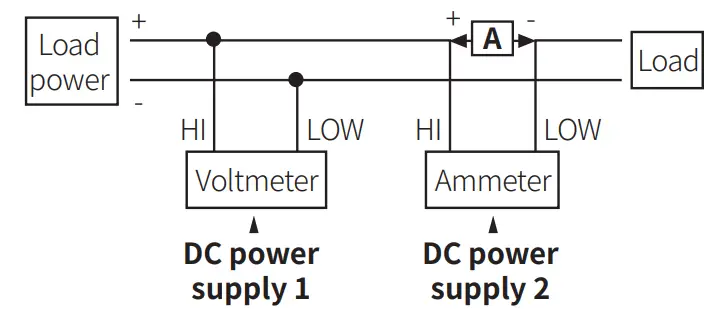
- A: Compared to measurement input range, higher measuring voltage needs a multiplier and lower measuring voltage needs a shunts.
- Connect the separated power supply each.
- (-) terminal of the power and (-) terminal of measurement input are shorted. In case of using same power supply, measurement error or overcurrent may occur.

- B: When measuring higher current than measurement input, use a shunt for DC current and a current transformed (C.T) for AC current.
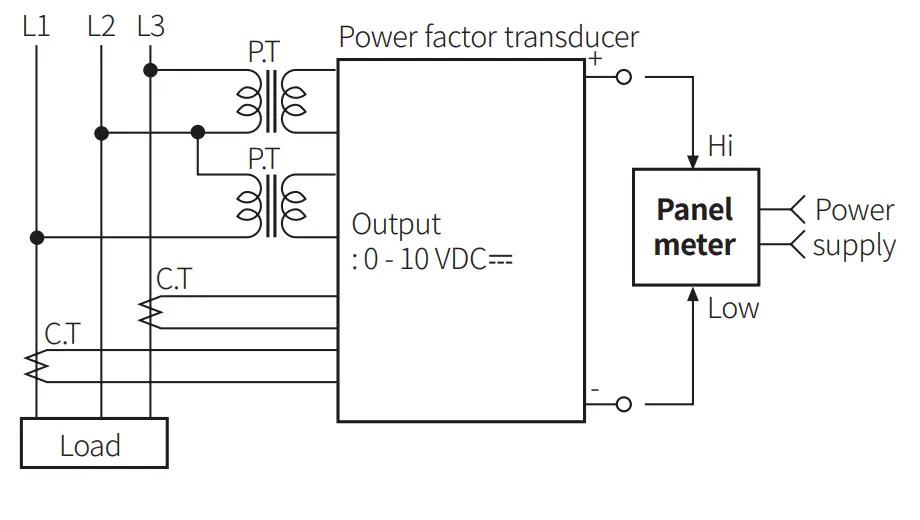
Power meter connection
Rotation / Speed meter connection
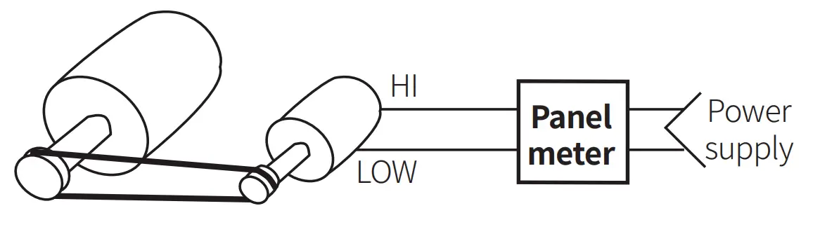
- Tacho generator (T.G) : This generator makes a voltage in proportion to revolution speed of motor. The panel meter receives the voltage and displays the number of revolution. There are AC voltage and DC voltage for output voltage.
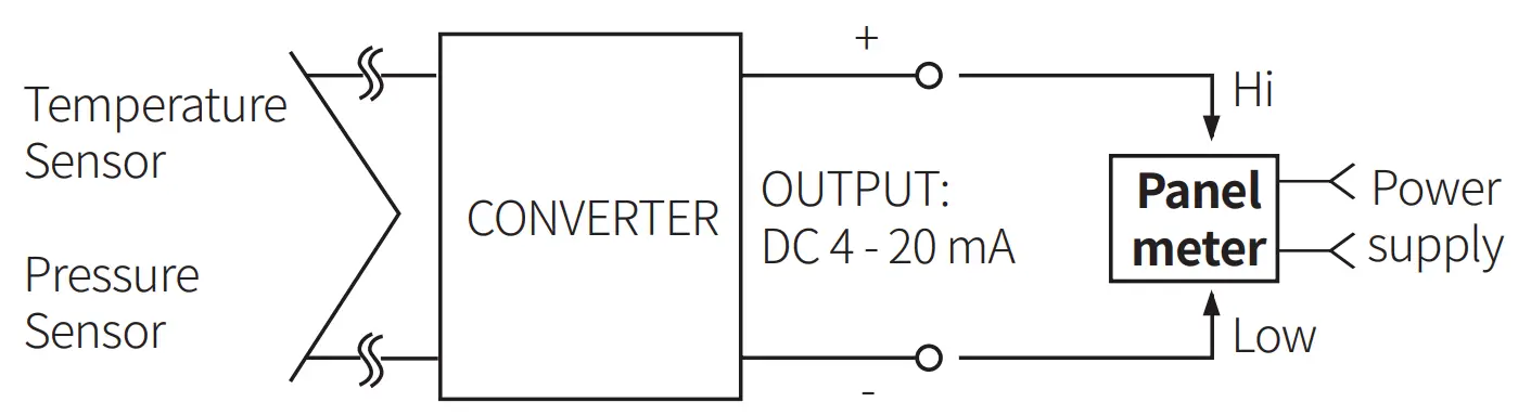
Scaling meter connection
CUSTOMER SUPPORT
18, Bansong-ro 513Beon-gil, Haeundae-gu, Busan, Republic of Korea, 48002
www.autonics.com | +82-51-519-3232 | [email protected]