![]() 1-Channel Digital Temperature Indicators
1-Channel Digital Temperature Indicators
KN-2000W Series
TCD210154AC
INSTRUCTION MANUAL
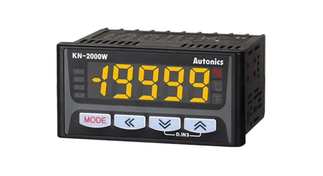
KN-2211W Digital Panel Meter
Thank you for choosing our Autonics product.
Read and understand the instruction manual and manual thoroughly before using the product.
For your safety, read and follow the below safety considerations before using.
For your safety, read and follow the considerations written in the instruction manual, other manuals and Autonics website.
Keep this instruction manual in a place where you can find easily.
The specifications, dimensions, etc are subject to change without notice for product improvement Some models may be discontinued without notice.
Follow Autonics website for the latest information.
Safety Considerations
- Observe all ‘Safety Considerations’ for safe and proper operation to avoid hazards.
 symbol indicates caution due to special circumstances in which hazards may occur.
![]() Warning Failure to follow instructions may result in serious injury or death
Warning Failure to follow instructions may result in serious injury or death
- Fail-safe device must be installed when using the unit with machinery that may cause serious injury or substantial economic loss.(e.g. nuclear power control, medical equipment, ships, vehicles, railways, aircraft, combustion apparatus, safety equipment, crime/disaster prevention devices, etc.)
Failure to follow this instruction may result in personal injury, economic loss or fire. - Do not use the unit in the place where flammable/explosive/corrosive gas, high humidity, direct sunlight, radiant heat, vibration, impact or salinity may be present.
Failure to follow this instruction may result in explosion or fire. - Install on a device panel to use.
Failure to follow this instruction may result in fire or electric shock. - Do not connect, repair, or inspect the unit while connected to a power source.
Failure to follow this instruction may result in fire or electric shock. - Check ‘Connections’ before wiring.
Failure to follow this instruction may result in fire. - Do not disassemble or modify the unit.
Failure to follow this instruction may result in fire or electric shock.
![]() Caution Failure to follow instructions may result in injury or product damage
Caution Failure to follow instructions may result in injury or product damage
- Use the unit within the rated specifications.
Failure to follow this instruction may result in fire or product damage - Use a dry cloth to clean the unit, and do not use water or organic solvent.
Failure to follow this instruction may result in fire or electric shock. - Keep the product away from metal chip, dust, and wire residue which flow into the unit.
Failure to follow this instruction may result in fire or product damage. - Check the polarity of the measurement input before wiring.
Failure to follow this instruction may result in explosion or fire.
Cautions during Use
- Follow instructions in ‘Cautions during Use’. Otherwise, it may cause unexpected accidents.
- For connecting the power, use the crimp terminal (M3.5, max. 7.2 mm)
- 24 VDC
 power supply should be insulated and limited voltage/current or Class 2, SELV power supply device.
 - Keep away from high voltage lines or power lines to prevent inductive noise. Do not use near the equipment which generates strong magnetic force or high frequency noise.
- Install a power switch or circuit breaker in the easily accessible place for supplying or disconnecting the power.
- Use twisted pair wire for communication line.
- This unit may be used in the following environments.
– Indoors (in the environment condition rated in ‘Specifications’)
– Altitude Max. 2,000 m
– Pollution degree 2
– Installation category II
Ordering Information
This is only for reference, the actual product does not support all combinations.
For selecting the specified model, follow the Autonics website .
- Alarm output
0: No ( Option output: Transmission is not available)
2: 2 alarm
4: 2 alarm - Option Output
0: No
1: PV transmission
4: Communication
5: PV transmission + Communication - Power supply
0: 100-240 VAC ∼ 50/60 Hz
1: 24 VDC
Product Components
- Product
- Instruction manual
- Bracket ×2
Software
Download the installation file and the manuals from the Autonics website.
■ DAQMaster
DAQMaster is comprehensive device management program. It is available for parameter setting, monitoring.
Specifications
| Series | KN-2000W Series | ||
| AC voltage | DC voltage | ||
| Power supply | 100 – 240 VAC- 50/60 Hz | 24 VDC | |
| Power consumption | ≤ 8 VA | ≤ 3 W | |
| Sampling period | • Thermocouple, RTD: 250 ms • Analog: 100 ms | ||
| Input specification | Refer to ‘Input Type and Using Range’. | ||
| Digital input | Contact | • ON: ≤ 2 kΩ • OFF: ≤ 90 kΩ | |
| Non contact | • Residual voltage: ≤ 1.0 V • Leakage current: ≤ 0.03 mA | ||
| Outflow current | ≈ 0.2 mA | ||
| Option output | Alarm | • 2 point relay: 250 VAC ∼ 3 A lc • 4 point relay: 250 VAC ∼ 1A la | |
| PV Transmission | ISOLATED DC 4-20 mA (Load resistance: 600 Ω) | ||
| RS485 comm. | Modbus RTU | ||
| Display type | 7 Segment (Red, Green, Yellow), LED type | ||
| Alarm output Hysteresis | 1 to 999 digit | ||
| Relay life cycle | Mechanical | · 2 point: ≥ 10,000,000 operations · 4 point: ≥ 20,000,000 operations | |
| Electrical | · 2 point: ≥ 100,000 operations(Load resistance: 250 VAC ∼ 3 A) · 4 point: ≥ 500,000 operations (Load resistance: 250 VAC ∼ 1 A) | ||
| Dielectric strength | Between input terminal and power terminal: 2,000 VAC ∼ 50/60 Hz for 1 min | ||
| Vibration | 0.75 mm amplitude at frequency of 5 to 55 Hz (for 1 min) in each X, Y, Z direction for 2 hours | ||
| Insulation resistance | ≥ 100 MΩ (500 VDC | ||
| Noise immunity | ±2 kV square shaped noise (pulse width 1 μs) by noise simulator | ||
| Memory retention | ≈ 10 years (non-volatile semiconductor memory type) | ||
| Ambient temperature | -10 to 50 °C, storage: -20 to 60 °C (no freezing or condensation) | ||
| Ambient humidity | 35 to 85%RH, storage: 35 to 85%RH (no freezing or condensation) | ||
| Approval | |||
| Unit weight (packaged) | ≈ 200 g (≈ 332 g) | ||
Communication Interface
■ RS485
| Comm. protocol | Modbus 1.1 RTU |
| Maximum connection | 32 units |
| Synchronous method | Asynchronous |
| Comm. method | Two-wire half duplex |
| Comm. effective range | ≤ 1,200 m (≤ 700 m recommended) |
| Comm. speed | 1,200 / 2,400 / 4,800 / 9,600 (default) / 19,200 bps (parameter) |
| Data bit | 8 bit (fixed) |
| Parity bit | None (fixed) |
| Stop bit | 1 bit (fixed) |
Input Type and Using Range
| Input type | Display | Using range (°C) | Using range (°F) | ||
| Thermo- couple | K (CA) | – 200.0 to 1350.0 | – 328 to 2462 | ||
| J (IC) | – 200.0 to 800.0 | – 328.0 to 1472.0 | |||
| E (CR) | – 200.0 to 800.0 | – 328.0 to 1472.0 | |||
| T (CC) | – 200.0 to 400.0 | – 328.0 to 752.0 | |||
| R (PR) | 0.0 to 1750.0 | 32 to 3182 | |||
| B (PR)* | 400.0 to 1800.0 | 752 to 3272 | |||
| S (PR)* | 0.0 to 1750.0 | 32 to 3182 | |||
| N (NN)* | – 200.0 to 1300.0 | – 328 to 237 2 | |||
| C (W5)* | 0 to 2300 | 32 to 4172 | |||
| L (IC)* | – 200.0 to 900.0 | – 328.0 to 1652.0 | |||
| U (CC)* | – 200.0 to 400.0 | – 328.0 to 752.0 | |||
| Platinel II* | 0.0 to 1390.0 | 32 to 2534 | |||
| RTD | Cu500* | – 200.0 to 200.0 | – 328.0 to 392.0 | ||
| Cul000* | – 200.0 to 200.0 | – 328.0 to 392.0 | |||
| J Pt100 0 | -200.0 to 600.0 | -328.0 to 1112.0 | |||
| DPt50 0 | – 200.0 to 600.0 | – 328.0 to 1112.0 | |||
| DPt100 0 | – 200.0 to 850.0 | – 328.0 to 1530.0 | |||
| Analog | Current | 0.00 – 20.00 mA | – 19999 to 19999 (Display range is variable according to decimal point position.) | ||
| 4.00 – 20.00 mA | |||||
| Voltage | – 50.00 – 50.00mV | ||||
| -200.0 – 200.0mV | |||||
| 1.0000 – 1.0000V | |||||
| – 1.000 – 10.000V | |||||
- Above input types which have the * mark are not displayed. To display the above input types, supply the power with pressing the [M] key.
■ Display accuracy
| Input type | Using temperature | Display accuracy |
| Thermocouple RTD | At room temperature (25 °C ±5 °C) | PV ±0.2% F.S. ±1 digit • Thermocouple below -100 °C: (PV ±0.4% F.S.) ± ldigit |
| Out of room temperature range | PV ±0.3% F.S. ±1 digit |
- In case of TC-T, TC-U, ±2.0 ℃ will be added to the degree standard.
Unit Descriptions
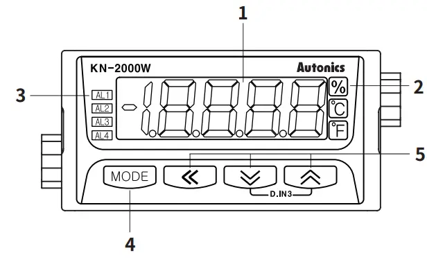
- Display part(Red)
Run mode: Displays PV (Present value).
Setting mode: Displays parameter and setting value. - Unit Indicator
Displays the set unit. - Alarm output indicator
Turns ON when the alarm is ON - [MODE] key
Used to enter parameter set mode, move to parameters, save SV and return to RUN mode. - [◀], [▲], [▼] key
Used to enter and change parameter setting value. - Selection switch for input specification
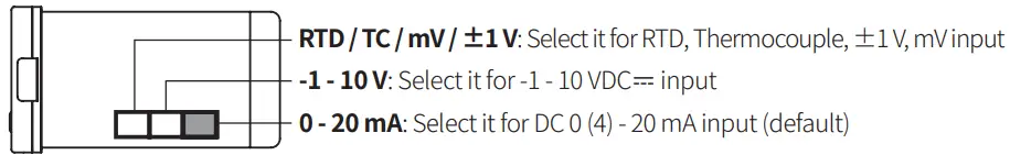
- The setting of input type selection switch and the setting value of input type parameter should be same and it can display the proper measurement value.
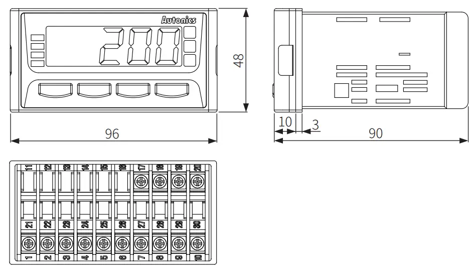
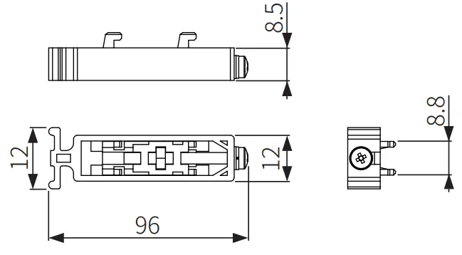
Dimensions
- Unit: mm, For the detailed drawings, follow the Autonics website.
■ Bracket
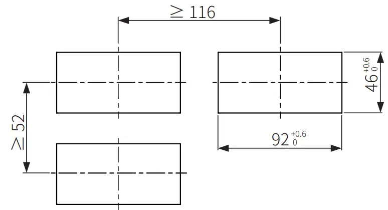
■ Panel cut-out
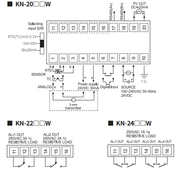
Connections
Errors
| Display | Description | Troubleshooting |
| Flashes when input sensor is disconnected or sensor is not connected. | Check input sensor status. | |
| Flashes when PV is higher than input range. | When input is within the rated input range, this display disappears. | |
| Flashes when PV is lower than input range. | ||
| Flashes when there is an error of setting value | Check the setting condition and reset. | |
| Flashes when parameter and selection switch setting for input specification are inconsistent | Check input specification. |
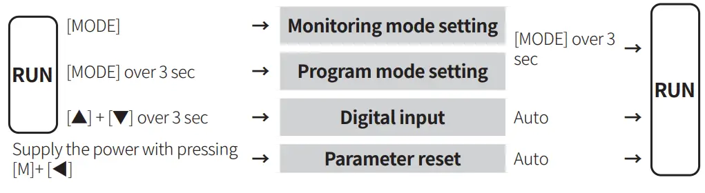
Mode Setting
Parameter Setting
- Some parameters are activated/deactivated depending on the model or setting of other parameters. Refer to the descriptions of each item.
- [MODE] key: Move to next item after saving / Return to RUN mode after saving (≥ 3 sec)
- [◀] key: Select parameter / Move digits
- [▲], [▼] key: Select parameter / Change setting value
- Return to the upper level without saving when there is no key input for more than 30 seconds.
■ Monitoring mode
| Parameter | Display | Default | Setting range | Condition | |
| 1-1 | AL1 alarm temperature | Within input range | 2-12/14/16/18 AL-1/2/3/4 alarm operation: AT1, AT2 | ||
| 1-2 | AL2 alarm temperature | ||||
| 1-3 | AL3 alarm temperature | [4 alarm output model] Same as 1-1/2 AL1/2 alarm temperature | |||
| 1-4 | AL4 alarm temperature | ||||
| 1-5 | High peak display | Check only (not available to set) Displays high/low peak (Max./Min. input) value • Initial high/low peak is saved after 2 sec from supplying the power. • Value reset: [▲] + [▼] key over 3 sec in 1-5/6 High/Low peak display parameter | – | ||
| 1-6 | Low peak display | ||||
■ Program mode
| Parameter | Parameter | Display | Default | Setting range | Condition | ||||||||||||
| 2-1 | Input specification | Refer to ‘Input Type and Using Range’. | – | ||||||||||||||
| 2-2 | Temperature unit | ℃, ℉ | 2-1 Input specification: Thermocouple, RTD | ||||||||||||||
| 2-3 | Display unit | %, OFF, ℃, ℉ | 2-1 Input specification: Analog | ||||||||||||||
| 2-4 | Low limit Input | Within input range, L-RG + 20% of F.S. ≤ H-RG | |||||||||||||||
| 2-5 | High limit Input | ||||||||||||||||
| 2-6 | Decimal point | 0.0, 0.00, 0.000, 0 | |||||||||||||||
| 2-7 | Low limit scale | -19,999 to 19,999 | |||||||||||||||
| 2-8 | High limit scale | -19,999 to 19,999 | |||||||||||||||
| 2-9 | 4 mA output scale | [PV transmission output model]
• Input: Thermocouple, RTD: Within input range • Input: Analog L-SC ≤ L.OUT + 10% of F.S. ≤ H.OUT ≤ H-SC | – | ||||||||||||||
| 2-10 | 20 mA output scale | ||||||||||||||||
| 2-11 | Input and transmission output extension 01) | [PV transmission output model]
| 2-1 Input specification: Analog | ||||||||||||||
| 2-12 | AL1 alarm operation | [Alarm output model]
□□□ AT0: Off AT1: Absolute high limit alarm AT2: Absolute low limit alarm SBA: Sensor break alarm | – | ||||||||||||||
| 2-13 | AL1 alarm option | A: Standard alarm C: Standby sequence B: Alarm latch D: Alarm latch and standby sequence • Enter to option setting: Press [◀] key in 2-15 AL-1 alarm operation. | – | ||||||||||||||
| 2-14 | AL2 alarm operation | [Alarm output model] Same as 2-12/13 AL1 alarm operation/option | – | ||||||||||||||
| 2-15 | AL2 alarm option | ||||||||||||||||
| 2-16 | AL3 alarm operation | [4 alarm output model] Same as 2-12/13 AL1 alarm operation/option | – | ||||||||||||||
| 2-17 | AL3 alarm option | ||||||||||||||||
| 2-18 | AL4 alarm operation | ||||||||||||||||
| 2-19 | AL4 alarm option | ||||||||||||||||
| 2-20 | Alarm output hysteresis | 001 to 999 | 2-12/14/16/18 AL-1/2/3/4 alarm operation: AT1, AT2 | ||||||||||||||
| 2-21 | Input special function | LIN: Linear, ROOT: Root, SQAR: Square, TUF: Two unit function | – | ||||||||||||||
| 2-22 | Input correction | -999 to 999 | – | ||||||||||||||
| 2-23 | Input digital filter | 01 (OFF) to 16 | – | ||||||||||||||
| 2-24 | Digital input Terminal | HOLD: Hold, ZERO: Zero-point adjustment, AL.RE*: Alarm reset *[Alarm output model] | – | ||||||||||||||
| 2-25 | Digital input key | ||||||||||||||||
| 2-26 | Display color | Tabile | – | ||||||||||||||
| 2-27 | Alarm display color 02) | [Alarm output model]
Select each digit separately. R: Red, G: Green, Y: Yellow | – | ||||||||||||||
| 2-28 | Sensor break alarm output | [Transmission output model] OFF: 4 mA – 5%, ON: 20 mA + 5% | – | ||||||||||||||
| 2-29 | Comm. Address | [Communication output model] 01to99 | – | ||||||||||||||
| 2-30 | Comm. speed | [Communication output model]
1.2K: 1200, 2.4K: 2400, 4.8K: 4800, 9.6K: 9600, 19.2K: 19200 bps | – | ||||||||||||||
| 2-31 | Comm. write | [Communication output model] EN.A: Enable, DIS.A: Disable | – | ||||||||||||||
| 2-32 | Lock | OFF LOC1: Program mode lock (check only) Monitoring mode unlock LOC2: Checking and setting program mode lock Monitoring mode setting lock (check only) | – |
01) Extension is not allowed below 0 mA and 0 V. ±1 V and 10 V Inputs cannot be set to 10P.
02) When alarm is cleared, or two alarms operate at the same time, the latest alarm’s color is applied.
When error occurs during alarm, the set color of ‘Display color’ parameter is applied.
Communication Parameter Setting
- Read Input Status (Func: 2, R/W: R)
| Address | Parameter | Output range | Condition |
| 100001 (0000) | AL1 indicator | 0: OFF, 1: ON | |
| 100002 (0001) | AL2 indicator | ||
| 100003 (0002) | AL3 indicator | ||
| 100004 (0003) | AL4 indicator | ||
| 100005 (0004) | °F indicator | ||
| 100006 (0005) | °C indicator | ||
| 100007 (0006) | % indicator |
Read Input Register (Func: 4, R/W: R)
| Address | Parameter | Output range | Condition |
| 300001 (0000) | Present value | -19999 – 19999 | |
| 300002 (0001) | Input specification | Refer to ‘Input specification parameter setting/output value’ | – |
| 300003 (0002) | Decimal point | 0004H: .0000, 0003H: 0.000, 0002H: 0.00, 0001H: 0.0, 0000H: 0 | 2-1 Input specification: Analog |
| 300004 (0003) | PWM OUT | 0 – 20000 | – |
| 300005 (0004) | X (MSB) | ||
| 0/0 indicator | 0: OFF, 1: ON | – | |
| °C indicator | |||
| °F indicator | |||
| AL4 indicator | |||
| AL3 indicator | |||
| AL2 indicator | |||
| AL1 indicator (LSB) |
Program mode setting group (Func: 03/06/16, R/W: R/W)
| Address | Parameter | Display | Setting range | Condition |
| 400001 (0000) | Input specification | Refer to ‘Input specification parameter setting/output value’ | Sameas each parameter setting condition | |
| 400002 (0001) | Temperature unit | 0: °C, 1: °F | ||
| 400003 (0002) | Display unit | 0: °C, 1: °F, 2: %, 3: OFF | ||
| 400004 (0003) | High limit Input | Same as parameter setting range | ||
| 400005 (0004) | Low limit Input | |||
| 400006 (0005) | High limit scale | Same as parameter setting range | ||
| 400007 (0006) | Low limit scale | |||
| 400008 (0007) | Input correction | Same as parameter setting range | ||
| 400009 (0008) | Input digital filter | Same as parameter setting range | ||
| 400010 (0009) | ALl alarm operation | 1:Absolute high limit alarm 2:Absolute low limit alarm 3:Sensor break alarm 4:No alarm | ||
| 400011 (000A) | AL2 alarm operation | |||
| 400012 (000B) | AL3 alarm operation | |||
| 400013 (000C) | AL4 alarm operation | |||
| 400014 (000D) | ALl alarm option | 10:Standard alarm 11:Alarm latch 1Z Standby sequence 13: Alarm latch and standby sequence | ||
| 400015 (000E) | AL2 alarm option | |||
| 400016 (000F) | AL3 alarm option | |||
| 400017 (0010) | AL4 alarm option | |||
| 400018 (0011) | Alarm output hysteresis | Same as parameter setting range | ||
| 400019 (0012) | 20 mA output scale | Same as parameter setting range | ||
| 400020 (0013) | 4 mA output scale | |||
| 400021 (0014) | Decimal point | 0004H: .0000, 0003H: 0.000, 0002H: 0.00, 0001H: 0.0, 0000H: 0 | ||
| 400022 (0015) | Input and transmission output extension | 0: 0%,1: 5%, 2: 10% | ||
| 400023 (0016) | Digital input Terminal | 0: Alarm reset, E Hold, Z Zero-point adjustment | ||
| 400024 (0017) | Digital input key | |||
| 400025 (0018) | Inputspecial function | 0: Linear, L. Root, Z Square, 3: Two Unit Function | ||
| 400026 (0019) | Sensor break alarm output | 0: ON, 1: OFF | ||
| 400027 (001A) | Lock | 0: OFF, 1: LOCK1, 2: LOCK2 | ||
| 400028 (001B) | Display color | 0: Red, E Green, Z Yellow, 3: Red-Green, 4: Green-Red | ||
| 400029 (001C) | ALl display color | 0: Red, L Green, 2: Yellow | ||
| 400030 (001D) | AL2 display color | |||
| 400031 (001E) | AL3 display color | |||
| 400032 (001F) | AL4 display color | |||
| 400033 (0020) | Comm. address | Same as parameter setting range | ||
| 400034 (0021) | Comm. speed | 0: 192000,1: 9600, 2: 4800, 3: 2400, 4: 1200 | ||
| 400035 (0022) | Comm. write | 0: Disable, E Enable |
- Func : Read Holding Register/Preset Single Register/Preset Multiple Register
Monitoring mode setting group (Func: 03/06/16, R/W: R/W)
| Address | Parameter | Display | Setting range | Condition |
| 400051 (0032) | ALl alarm temperature | Same as parameter setting range | Same as each parameter setting condition | |
| 400052 (0033) | AL2 alarm temperature | |||
| 400053 (0034) | AL3 alarm temperature | |||
| 400054 (0035) | AL4 alarm temperature | |||
| 400055 (0036) | High peak display | Same as parameter setting range | ||
| 400056 (0037) | Low peak display |
■ Input specification parameter setting/output value
| Input spec. | Display | Value | |
| Thermocouple | 1 | ||
| 2 | |||
| 3 | |||
| 4 | |||
| 5 | |||
| 6 | |||
| 7 | |||
| 8 | |||
| 9 | |||
| 10 | |||
| 11 | |||
| RTD | 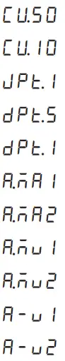 | 12 | |
| 13 | |||
| 14 | |||
| 15 | |||
| 16 | |||
| Analog | Current | 17 | |
| 18 | |||
| Voltage | 19 | ||
| 20 | |||
| 21 | |||
| 22 | |||
18, Bansong-ro 513Beon-gil, Haeundae-gu, Busan, Republic of Korea, 48002
www.autonics.com | +82-2-2048-1577 | [email protected]


