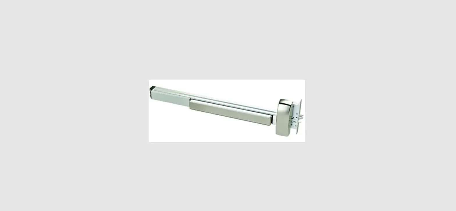
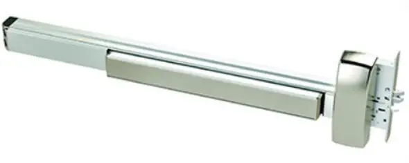
PDQ 6400R RF Exit Rim Device
INSTALLATION INSTRUCTION
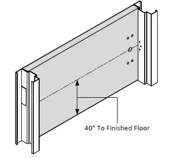
PREPARE DOOR
- Prepare door and frame according to template.
- Refer to trim template if installing trim.

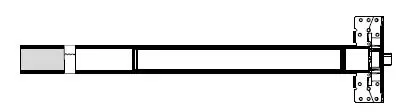
SIZE DEVICE
- Standard lengths are for 36″ or 48″ door. Device must be cut for other lengths.
- Mark length with tape – length equals device size minus desired door size (for 30″ door = cut 6″ off 36″ device) ensuring a square cut.

| Maximum cut off length: | ||||
| Panic | Fire | Alarm | MLR | |
| 36″ Device | 6″ | 8″ | 2″ | 3″ |
| 48″ Device | 12″ | 14″ | 8″ | 9″ |
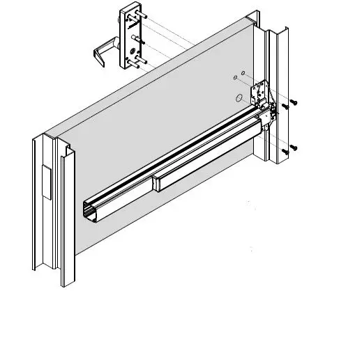
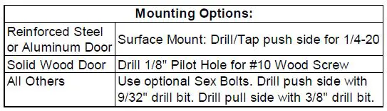
INSTALL DEVICE
- Install device and trim with 1/4-20 screws from pack #639043.
- Device can be surface mounted to the door, optional sex nuts are available, device is through bolted if using trim.

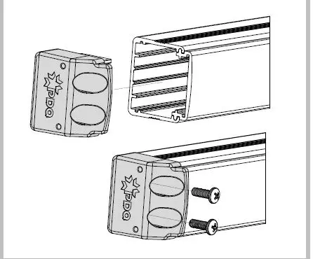
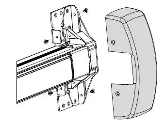
INSTALL END CAP
- Slide end cap into rail. Ensure rail is level. Mark the centers of the slots.
- Remove end cap then drill holes using the chart from Step 3.
- Reinstall end cap and fasten with screws.

INSTALL HEAD COVER
- Slide head cover onto exit device
- Install 4 mounting screws

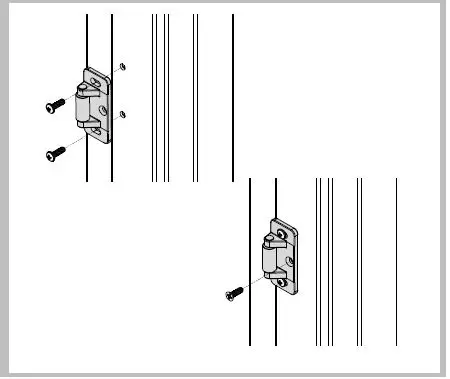
INSTALL STRIKE
- Install strike with roller toward door face using two #10-24 pan head screws.
- Adjust strike to secure door.
- Install flat head locking screw by drilling and tapping for #10-24 after final adjustment is achieved.