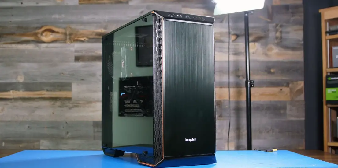
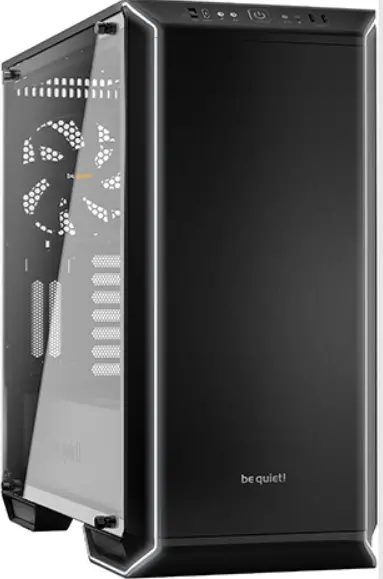
be quiet Dark Base 700 Silent High-end PC Cases
INTRODUCTION
We are delighted you have chosen to buy our Dark Base PC case. Please read the information here and carefully follow all the instructions prior to installation. Should you have further questions, please contact our customer service. See contact information in the manufacturer’s details section.
Warranty
- 3-year manufacturer’s warranty for the consumer (original purchase from authorized be quiet! dealers only)
- Your original receipt of purchase will be required before warranty services are rendered. Please store it carefully.
- Manipulations and/or technical modifications of any kind, or damage due to the application of mechanical force, will void your warranty.
- To read the warranty terms and conditions in full, see Service/Warranty Conditions on our website at bequiet.com.
Our General Terms and Conditions of Business also apply. For details please refer online under bequiet.com.
Manufacturer’s details
Listan GmbH & Co. KG | Biedenkamp 3a | 21509 Glinde | Germany
For support in Germany, you can call our free service hotline
Monday through Friday 09:00 – 17:30 (UTC+1)
Tel. 0049 40 736 7686 – 44 Fax 0049 40-7367686-69
Email: [email protected]
Internet page: www.bequiet.com
Copyright
- You are not allowed to reproduce, disclose, publish or store the contents of this documentation, or excerpts of it, without the prior written consent of Listan.
- be quiet! is a registered trademark of Listan GmbH & Co. KG. Other products and company names mentioned in this documentation may be the brands or trademarks of their respective owners.
- In accordance with company policy, all Listan products are subject to ongoing development. Listan reserves the right to make changes and improvements to any product described in this document without prior notice.
- Under no circumstances shall Listan be held liable for loss of data or income, or for any specific, incidental, direct, or indirect damage, however it arises.
- The content of this documentation represents the status at time of writing. Listan does not assume, whether expressed or implicit, any liability for the correctness or completeness of the content of this documentation, including, but not limited to the implicit guarantee of market suitability and fitness for a particular purpose, unless applicable laws or jurisdiction specifically stipulate such a liability.
Listan reserves the right to make changes to this documentation or to withdraw the documentation at any time without prior announcement.
SPECIFICATIONS
| Dimensions (W x H x D in mm) | 241 x 519 x 544 |
| Case Type | Midi Tower |
| Material
| 0.7 – 0.8mm SECC steel, 0.8 – 1.2mm aluminum, ABS plastic, 4mm tempered glass |
| Motherboard Support | E-ATX (30.5 x 27.5cm), ATX, M-ATX, Mini-ITX |
| Front I/O
| 2x USB 3.0, 1x USB 3.1 Type C, HD audio (mic + headphone jacks), RGB control switch, 4-step fan controller |
| Fan Speed Controller | 6x 4-pin, Step Controller, PWM hub |
| Max. Cooler Height (mm) | 180 |
| Max. Graphics Card Length (mm) | 286 / 430 (w/o HDD cage) |
| PSU Length (mm) | 150 – 285 |
| PCI Slots | 7 + 2 |
| 3.5” Bay | 7 |
| 2.5” Bay | 3 + 6 |
| Cooling Fans (mm) / (rpm)
| Front: 1x SilentWings® 3 140mm / 1,600 Rear: 1x SilentWings® 3 140mm / 1,600 |
| Optional Cooling Fans
| Front: 2x 140/120 Top: 3x 140/120 PSU shroud: 1x 140/120 Bottom: 1x 140/120 |
| Radiator Support (mm)
| Front: 120, 140, 240, 280, 360 Top: 120, 240, 360 Rear: 120, 140 |
| Additional Features
| Switchable multi mode, multi color RGB LED lighting at the front panel (white, red, green, blue, orange, purple), support of motherboard LED control |
CONTENTS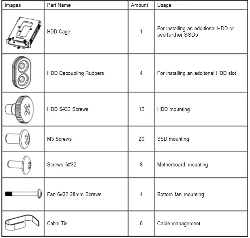
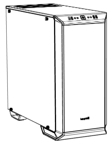
EXPLODED VIEW & DESCRIPTION OF PARTS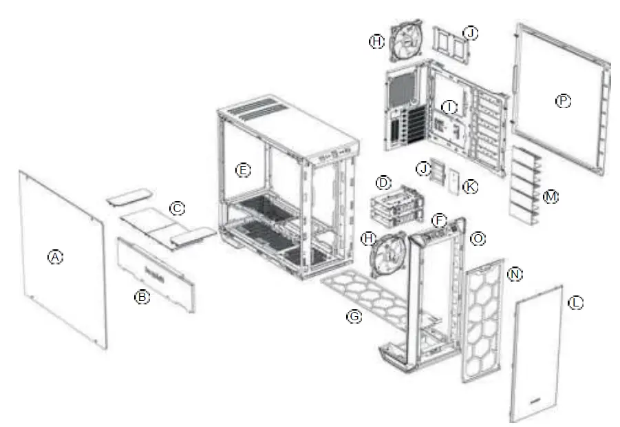
| A | Tempered Glass Window | I | Motherboard Tray |
| B | Front Cover PSU Shroud | J | SSD Tray |
| C | Top Cover PSU Shroud | K | Fan and LED Controller PCB |
| D | HDD Slots | L | External Front Cover |
| E | Chassis Body | M | HDD Slot Cover |
| F | Front IO Panel | N | Front Air Filter |
| G | Base Air Filter | O | Front Panel |
| H | SilentWings® 3 Fan | P | Side Panel |
FRONT I/O AND MEDIA PORTS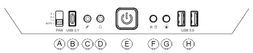
| A | Fan Controller Switch | E | Power Button |
| B | USB 3.1 Type C | F | HDD LED / Reset |
| C | Microphone | G | LED Switch |
| D | Headphone | H | USB 3.0 |
I/O PORTS
The Front I/O ports provided require connections to your motherboard. Refer to your motherboard handbook for information on pin assignments and sockets.
HD audio (headphone jack/microphone jack)
Find the HD audio pin connectors on your motherboard and attach the HD audio cables to the designated sockets.
USB 3.1 Type C
Find the USB 3.1 Type C pin connectors and attach the USB 3.1 Type C cables to the designated sockets.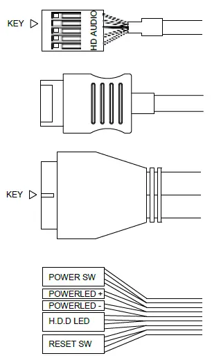
USB 3.0
Find the USB 3.0 pin connectors on your motherboard and attach the USB 3.0 cables to the designated sockets.
On/Off Switch, Power On LED, Disk Operating LED, Reset Button
The plugs illustrated connect the On/Off Switch and LED lamps of the case to your motherboard. Take care you observe the correct polarity with the LEDs.
PCB PANEL / PORTS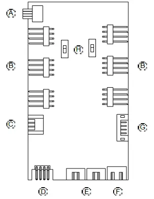
| A | 4-Pin PWM connector to motherboard |
| B | 4-Pin PWM connector to fan |
| C | LED connector to motherboard |
| D | LED outlet for additional external LEDs |
| E | Connecting plug for the front LEDs |
| F | SATA power connection |
| G
| Ports for fan controller switch connector and LED switch on front I/O panel |
| H
| Switch for choosing between Silence and Performance Mode |
Please note: To ensure proper functioning of the fan control and the LED lighting, make sure that cable F is connected to the power supply.
FAN CONTROLLER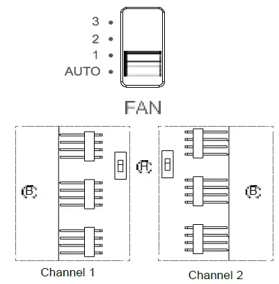
The fan controller has two modes of operation.
- Automatic operation
In this mode the PWM signal of the motherboard is used and the speeds of all PWM fans connected can be adjusted automatically by the motherboard. The fan speed slider control must be set to its initial position of “AUTO” in this case. In order to use the automatic PWM control of the fans it is necessary to connect the cable “A” of the PCB panel (4.3) with the PWM connector of your motherboard. Lacking such a connection it is only possible to manually control the speeds of fans connected. - Manual control
When the fan speed slider control is moved up from its initial position of “AUTO“ the PWM signal is ignored and the fan speed can be manually set to one of three constant speeds. In total it is possible to connect six PWM fans to the fan controller PCB. These six connections are subdivided into two channels (right and left) each with three connections. By operation of switch “H” on the PCB these channels can be switched independently from one another between “Silence” and “Performance” modes. The rate factors of the PWM fans connected here are determined as set out below according to the setting of the front I/O fan switch.
Performance Mode
In combination with the Front I/O switch
50% | 800rpm* (Position 1)
70% | 1,120rpm* (Position 2)
100% | 1,600rpm* (Position 3)
Silence Mode
In combination with the Front I/O switch
25% | 400rpm* (Position 1)
45% | 640rpm* (Position 2)
65% | 1,040rpm* (Position 3)
*with SilentWings® 3 1,600rpm
When the slider control is returned to its initial position of “AUTO“ the PWM signal of the motherboard resumes control of the fans.
HANDLING OF THE LED ILLUMINATION
The LED illumination preinstalled in the front can be configured in several colors and operating modes. Further strips of LED illumination for lighting the case interior can be plugged into socket “D” on LED controller PCB (4.3) with a maximum combined rating of 24 watts.
WARNING! Only 12V LEDs may be connected.
To switch between synchronized operation and manual control mode keep switch “G“ pressed for about three seconds.
Synchronized operation
It is possible to connect cable “C” of the PCB (4.3) and the corresponding RGB LED controller socket of your motherboard. The integrated illumination can then be controlled by the motherboard. For information on operation of the LED controller of your motherboard refer to your motherboard handbook. In manual mode you can cycle through the available colors (white, red, green, blue, orange, purple) by briefly pressing switch “G”. An intermediate stage between each color enables “breath mode” for the previously selected color.
The individual switch stages are:
| 1 | White | 8 | Blue breath |
| 2 | White breath | 9 | Orange |
| 3 | Red | 10 | Orange breath |
| 4 | Red breath | 11 | Purple |
| 5 | Green | 12 | Purple breath |
| 6 | Green breath | 13 | Breath mode alternately in all colors |
| 7 | Blue | 14 | LEDs off |
FAN COMPATIBILITY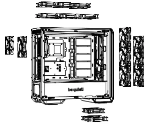
| Position | Fan Size (mm) |
| Top | 3x 120, 3x 140 |
| Bottom | 1x 120, 1x 140 |
| Front | 3x 120, 3x 140 |
| Rear | 1x 120, 1x 140 |
| PSU Shroud | 1x 120, 1x 140 |
RADIATOR SUPPORT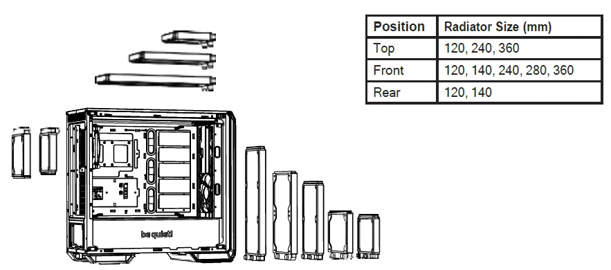
| Position | Radiator Size (mm) |
| Top | 120, 240, 360 |
| Front | 120, 140, 240, 280, 360 |
| Rear | 120, 140 |
REMOVAL OF THE SIDE PANELS
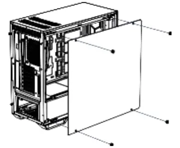
To remove the glass side panel, unscrew the four fixing screws as shown.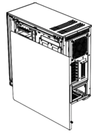
To remove the steel side panel, unscrew the two screws as shown and draw the side panel towards the rear with the grip provided for its purpose.
INSTALLATION AND REMOVAL OF DRIVES AND FILTERS
Install an HDD into the 3.5“ slot using the four screws.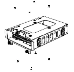
It is possible to install two SSDs (top and bottom) into each HDD slot.
INSTALLATION OF SSDs ON THE BRACKET BEHIND THE MOTHERBOARD TRAY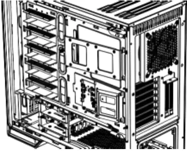
Remove the SSD tray by unscrewing the fixing screws.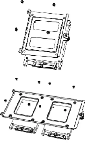
Affix the SSD and refit the bracket into the case.
HDD-SLOT COVERS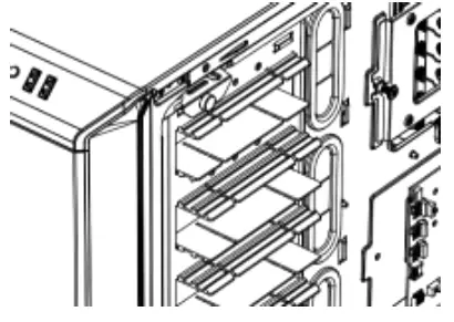
The five HDD slot covers supplied can be mounted in three steps to fully cover the holes or keep them partly open.
According to requirements, they can be removed or repositioned to install VGA cards or for cable management.
To optimize the cable routing up to two individual segments of the covers can be „punched out“ if necessary.
Warning: Punched out segments cannot be refitted.
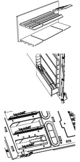
AIR FILTER REMOVAL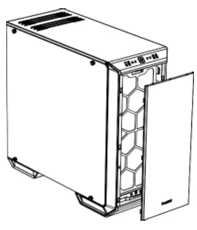
To remove or clean the air filter the front panel of the case must first be detached. To do this, grasp behind the front edge of the panel from the front and pull it off towards you.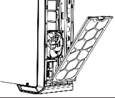
By depressing the hooks on top, unlatch and remove the front filters as shown.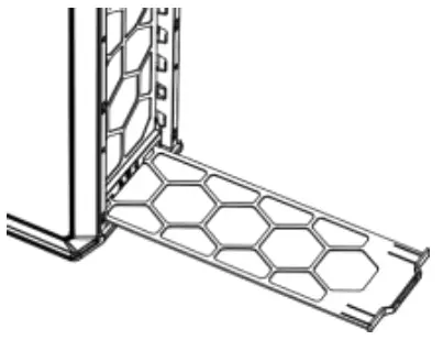
Slide out the bottom filter to the front.
INVERTED LAYOUT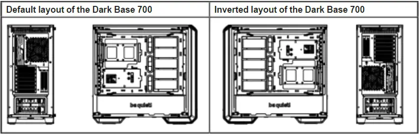
How to switch to inverted layout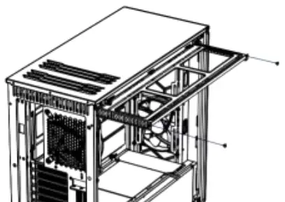
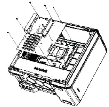
Remove both screws and detach the radiator/ fan bracket from the upper part of the case.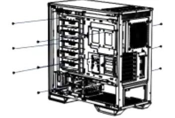
Remove the nine screws of the motherboard tray.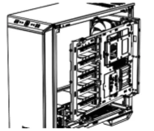
Now withdraw the motherboard tray from the case.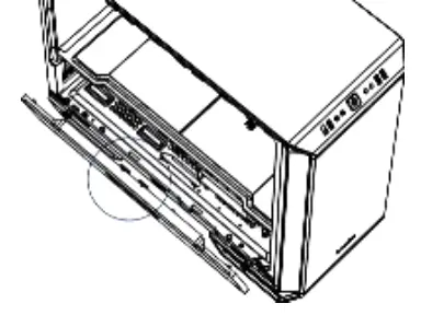
To remove the PSU front panel, depress the centrally marked portion and detach it.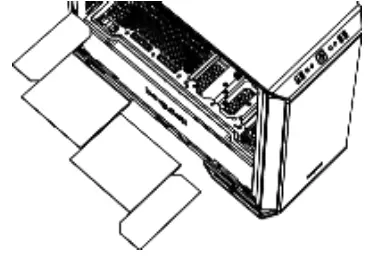
Remove the four top panels of the PSU cover.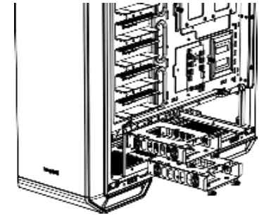
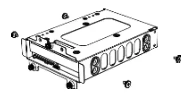
To dismantle the HDD tray, first remove the two HDD slots by unscrewing each of the three fixing screws.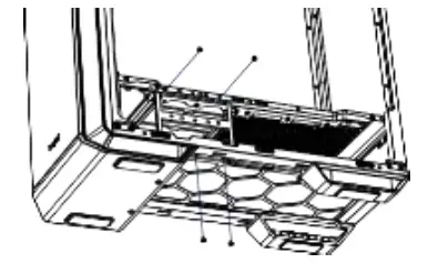
Remove the four screws of the HDD tray.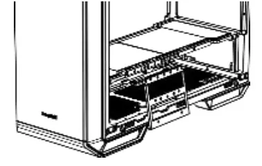
Remove the HDD tray from the case.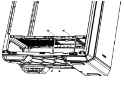
Now put the HDD tray back on the opposite side and mount it as described in the previous steps.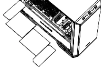
Put back the four panels of the PSU cover.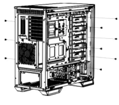
Now reinsert the motherboard tray into the case and fasten it with the nine previously removed screws.
Put back the radiator/fan bracket and secure this again with its two screws. Refit the PSU front panel.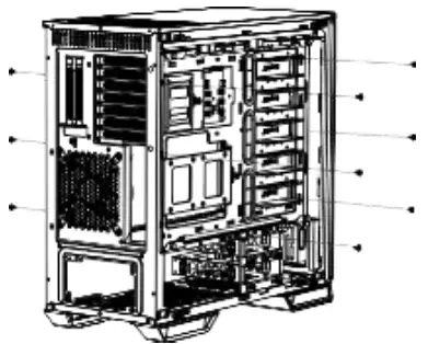
Remove the four screws (including the decoupling rubber) used to mount the glass side panel.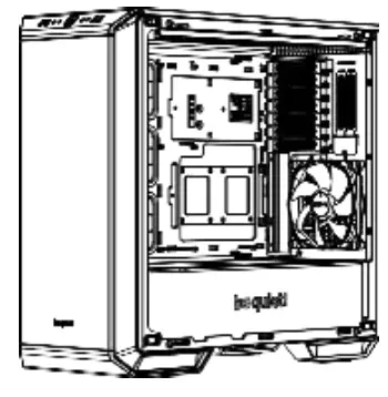
Refit the screws (including the decoupling rubber) to remount the glass side panel on the opposite side.
INSTALLATION OF COMPONENTS
Motherboard
Attach the motherboard with the M3 screws supplied. Standoffs are preinstalled for installation of an ATX motherboard.
Test Bench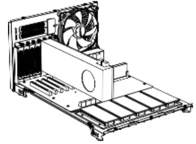
If required, the motherboard tray can be removed (see instructions for this under 9.) and used as a test bench.
PCI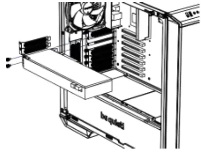
Before you start to install a PCI / PCI-E addon- card, first remove the PCI slot cover.
VGA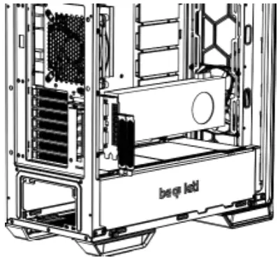
VGA cards can also be installed vertically. The “Raiser Card” that is needed to achieve this is not included in the scope of delivery.
PSU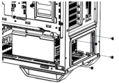
Place the PSU into the housing and secure it with the screws supplied by the PSU manufacturer.
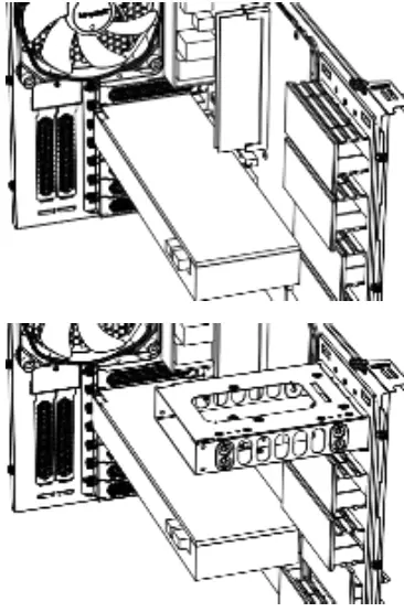
Top Radiator
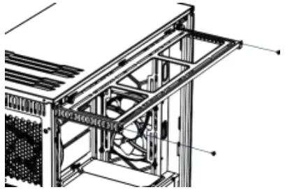
Unscrew the two screws that secure the radiator/fan bracket and slide this out.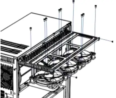
Fit your radiator or fans onto the mounting bracket and secure these with screws as illustrated.
Limited Warranty
Per the terms and conditions of this limited warranty as given below, be quiet! warrants its new products to be free of defects resulting from faulty materials and faulty manufacturing for the length of the warranty period.
- APPLICABILITY
This non-transferable warranty is applicable to newly purchased, previously unopened be quiet! products and is enforceable by only the original consumer purchaser. Proof of purchase is required for warranty service, so should be retained. be quiet! does not provide warranty registration services. - WARRANTY PERIOD
For eligible products, parts and labor are warranted for the applicable warranty period from the date of purchase. The applicable warranty period varies by product model, and is identified in your user documentation, on the product package, or as listed below. Should any of these warranty periods differ, the longest specified warranty period will apply. Replaced products will be warranted for the remainder of the original warranty period or thirty days, whichever is longer. - EXCLUSIONS
The following are not covered by the warranty:- Normal wear and tear.
- Any product which has been modified without permission from be quiet!, or on which the serial number or warranty sticker has been defaced, modified, or removed.
- Damage, deterioration or malfunction resulting from: Accident, abuse, misuse or improper use, neglect, connection to an improper voltage source, unauthorized product modification, or failure to follow instructions included with the product. Fire, water, lightning, or other acts of nature. Repair or attempted repair by anyone not authorized by be quiet!. Shipping or transport damage (claims must be made with the carrier). Any other cause which does not relate to a defect in materials or manufacturing workmanship.
- Cartons, cases, batteries, cabinets, tapes, accessories or other consumables used with this product.
- be quiet!, Inc. does not warrant that this product will meet your requirements. It is your responsibility to determine the suitability of this product for your purpose.
- Removal or installation charges.
- Shipping charges.
- Any incidental charges.
- EXCLUSION OF DAMAGES
be quiet!‘s sole obligation and liability under this warranty is limited to the repair or replacement of a defective product at its option. be quiet! shall not, in any event, be liable for any special, incidental, indirect, or consequential damages whatsoever, including but not limited to loss of profits, revenue, or data (whether direct or indirect), damages resulting from interruption of service and loss of business, or for liability in tort relating to this product or resulting from its use or possession, even if be quiet! has been advised previously of the possibility of such damages. - LIMITATIONS OF IMPLIED WARRANTIES
There are no other warranties, expressed or implied, including but not limited to those of merchantability or fitness for a particular purpose. The duration of implied warranties is limited to the warranty length specified in Paragraph II. - LOCAL LAW AND YOUR WARRANTY
This warranty gives you specific legal rights. You may also have other rights granted under local law. These rights may vary. - NO OTHER WARRANTY
No be quiet! employee, dealer, or other agent is authorized to make any modification, extension, or addition to this warranty. - TO OBTAIN TECHNICAL SUPPORT OR WARRANTY SERVICE
Please see your product owner’s manual or visit the Online Support section at www.bequiet.com for details and contact information. You will need to provide proof of purchase for warranty service.
References
 be quiet! - Silent PSUs, cases and PC cooling products. PSU calculator and cooler check for your PC
-
下載所有be quiet! 產品
-
Quiet.fr
-
be quiet! - Silent PSUs, cases and PC cooling products. PSU calculator and cooler check for your PC
-
be quiet! - Silent PSUs, cases and PC cooling products. PSU calculator and cooler check for your PC


