steinel iHF 3D Motion Detector
STEINEL Vertrieb GmbH
Dieselstraße 80-84
33442 Herzebrock-Clarholz
Tel: +49/5245/448-188
www.steinel.de
About this document
Please read carefully and keep in a safe place.
- Under copyright. Reproduction either in whole or in part only with our consent.
- Subject to change in the interest of technical progress.
General Safety Notification
Disconnect the power supply before attempting any work on the unit.
- During installation, the electric power cable to be connected must not be live. Therefore, switch off the power first and use a voltage tester to make sure the wiring is off-circuit.
- Installing the sensor involves work on the mains power supply.
This work must therefore be carried out professionally in accordance with national wiring regulations and electrical operating conditions. - Only use genuine replacement parts.
- Repairs may only be made by specialist workshops.
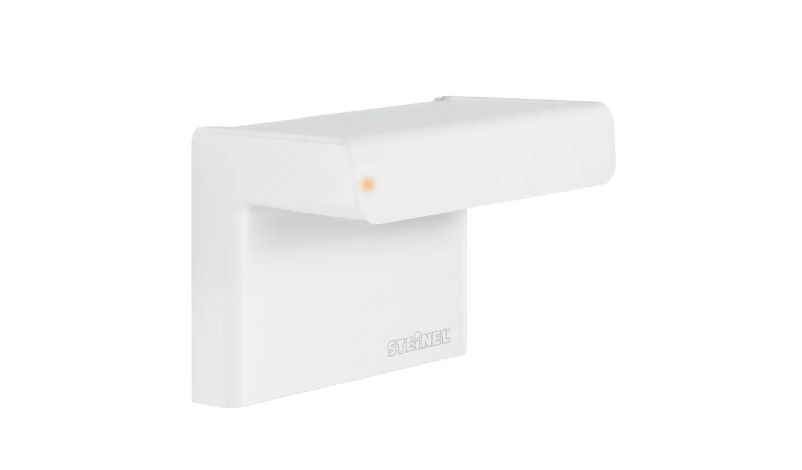
iHF 3D
Proper use
The iHF 3D sensor is an active motion detector for wall mounting outdoors.
The iHF 3D sensor emits high-frequency electromagnetic waves (5.8 GHz) and receives their echo. Any movement by persons in the detection zone is noticed by the sensor as a change in echo and triggers a switching signal. Analysing the signal, the iHF 3D sensor distinguishes between moving persons and moving objects, such as bushes or small animals (animals up to the size of a cat). The 3D antenna system permits precision adjustment in any way in three directions. This rules out any inadvertent triggering by small animals as well as interference from extreme temperatures.
Note: The high-frequency output of the iHF-sensor is approx.1 mW – that’s 1000 times less than the transmission power of a mobile phone or the output of a microwave oven.
Package contents (Fig. 3.1)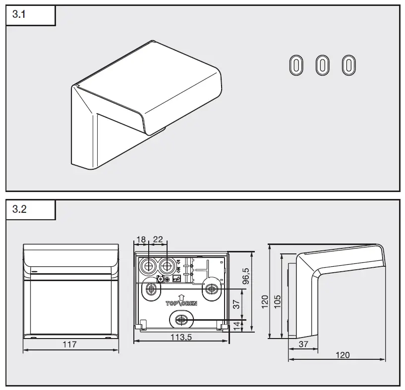
Product dimensions (Fig. 3.2)
Mounting height/reach (Fig. 3.3)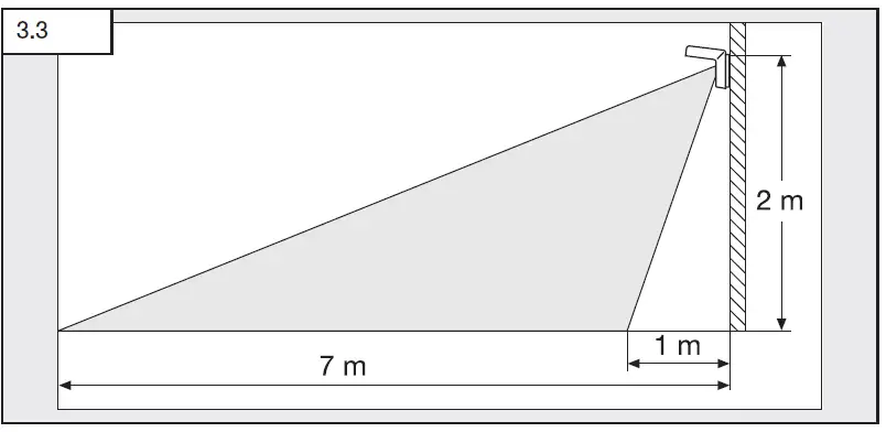
Product components (Fig. 3.4)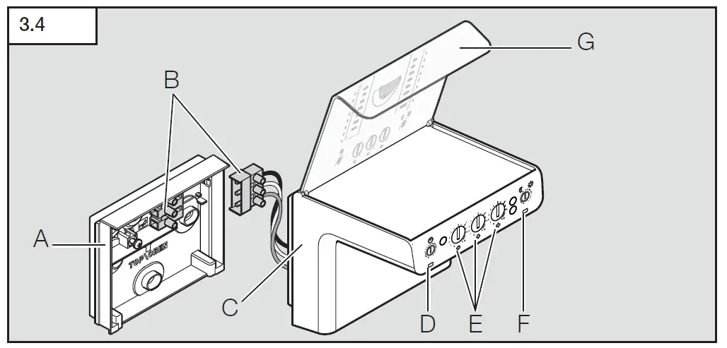
- A Wall mount
- B Plug connection
- C Sensor unit
- D Time setting
- E 3D reach setting
- F Light-level setting
- G Designer cover panel
Installation
Switch OFF power supply (Fig. 4.1)
Wiring diagram (Fig. 4.2)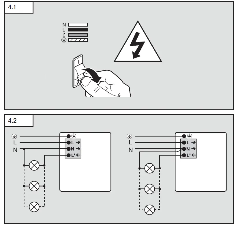
Connect the mains power supply lead (Fig. 4.3)
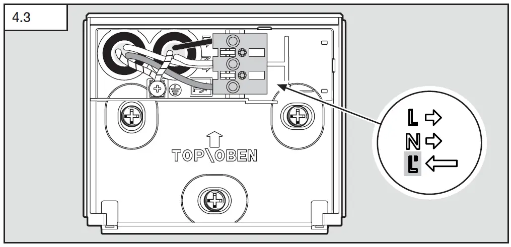
The mains supply lead is a 3-core cable (max. lead diameter 19 mm):
L = phase conductor (usually black, brown or grey)
N = neutral conductor (usually blue)
L’ = live conductor (usually black or brown)
If you are in any doubt, identify the conductors using a voltage tester; then disconnect from the power supply again. Connect phase (L) and neutral conductor (N) to the terminal block.
Please note that the electric circuit must be protected by a 16A circuit breaker.
Important: Incorrectly wired connections will produce a short circuit later on in the product or your fuse box. In this case, you must identify the individual conductors once again and re-connect them. A mains power switch for turning the unit ON and OFF may of course be installed in the mains supply lead.
Mounting
- Check all components for damage.
- Do not use the product if it is damaged.
Mounting procedure
- Select appropriate site of installation, giving consideration to sensor reach and detection of movements (Fig. 3.3)
- Switch OFF power supply (Fig. 4.1)
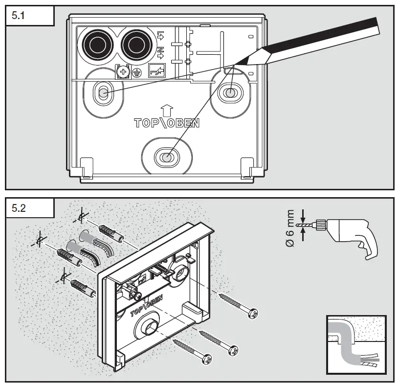
- Mark drill holes (Fig. 5.1)
- Drill holes and insert wall plugs (Fig. 5.2)
- Concealed power supply lead (Fig. 5.2)

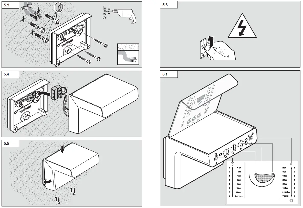
- Surface-mounted power supply lead (Fig. 5.3)
- Concealed power supply lead (Fig. 5.2)
- Connect conductors (Fig. 4.2)
- Make plug connection (B) (Fig. 5.4)
- Screw sensor unit (C) into place (Fig. 5.5)
- Switch ON power supply (Fig. 5.6)
- Make settings ➔ “6. Operation”
Operation
Operation/function legend (Fig. 6.1)
Note: After connecting to the mains power supply, the white Status-LED flashes for 10 s. The sensor is then ready for operation.
Factory settings
Time setting: Install (pos. 8)
Reach setting: 3x MAX
Light-level setting 1000 lux (pos. 7)
Functions
Time setting
The time you wish the connected load to stay ON for can be adjusted to any of six settings: 30 seconds, 1 minute, 2 minutes, 5 minutes, 15 minutes to 30 minutes.
Pulse mode
If you set the control dial to (pos. 1), the unit is in pulse mode, i.e. the output is switched ON for approx. 2 sec. (e.g. for staircase lighting timer). Afterwards, the sensor does not react to movement for approx. 8 s.
Install mode
Install mode has the purpose of checking for proper working order as well for testing the detection zone. Irrespective of light level, the light connected switches ON for 10 seconds (status LED flashes; see “LED Status” table in Section 7). Install mode has priority over all other settings.
Change control dial setting to quit Install mode.
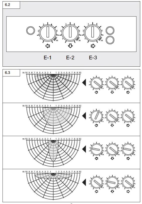
Reach setting (Fig. 6.2 / E 1-3)
Reach can be infinitely adjusted in three direc-tions via three control dials from 1-5 m (max. approx. 7 m) independently of each other. The maximum detection reach is selected via the control dials.
Detection diagram (Fig. 6.3)
Note: if the distance to a wall or similar structure is less than 7 m in any of these directions, the reach in that direction must still be set to maximum reach or detection errors may be made. The reach settings should only be used to mask out areas in which you do not want movement to result in light being switched ON. Performance of the iHF 3D may also be impaired by installing it in corners or on metal building exteriors.
Light-level setting (Response threshold)
The sensor’s chosen response threshold can be infinitely varied from approximately 2 to 1000 lux.
Teach mode
Teach mode saves the current ambient light level below which you do not want the sensor to respond to movement from now on.
SMART REMOTE Bluetooth function
STEINEL Smart Remote app
To configure the light via smartphone or tablet, you must download the STEINEL Smart Remote app from your app store. You will need a Bluetooth-capable smartphone or tablet.
LED status
| State / Event | LED Mode | Colour |
| Initialization (CPU locked) | Stable light | White |
| Changing potentiometer values | Flashing X times
If the poti value is changed by 4 positions, LED flashes fast 4 times. | White |
| Bluetooth connection | Flashing twice 0.5 sec. ON 0.5 sec. OFF 0.5 sec. ON 0.5 sec. OFF | Blue |
| 4 h ON / 4 h OFF | Stable light | Magenta |
| Standard operation (Sensor mode) | OFF | |
| Test (Install) Mode No movement detected | Stable light | Cyan (10% brightness) |
| Test (Install) Mode Movement detected | Stable light for 10 seconds | Cyan (100% brightness) |
EC Declaration of Conformity
Hereby, STEINEL Vertrieb GmbH declares that the radio equipment type iHF 3D is in compliance with Directive 2014/53/EU. The full text of the EU declaration of conformity is available at the following internet address: www.steinel.de
Disposal
Electrical and electronic equipment, accessories and packaging must be recycled in an environmentally compatible manner.
Do not dispose of electrical and electronic equipment as domestic waste.
For EU countries only:
under the current European Directive on Waste Electrical and Electronic Equipment and its transposition in national law, electrical and electronic equipment no longer suitable for use must be collected separately and recycled in an environmentally compatible manner.
Manufacturer’s warranty
As purchaser, you are entitled to your statutory rights against the vendor. If these rights exist in your country, they are neither curtailed nor restricted by our Warranty Declaration. We guarantee that your STEINEL Professional sensor product will remain in perfect condition and proper working order for a period of 5 years. We guarantee that this product is free from material-, manufacturing- and design flaws. In addition, we guarantee that all electronic components and cables function in the proper manner and that all materials used and their surfaces are without defects.
Making Claims
If you wish to make a claim, please send your product complete and carriage paid with the original receipt of purchase, which must show the date of purchase and product designation, either to your retailer or contact us at STEINEL (UK) Limited, 25 Manasty Road, Axis Park, Orton Southgate, Peterborough, PE2 6UP, for a returns number. For this reason, we recommend that you keep your receipt of purchase in a safe place until the warranty period expires. STEINEL shall assume no liability for the costs or risks involved in returning a product.
For information on making claims under the terms of the warranty, please go to www.steinel-professional.de/garantie
If you have a warranty claim or would like to ask any question regarding your product, you are welcome to call us at any time on our Service Hotline 01733 366700.
Technical Specifications
| Dimensions (H × W × D) | 120 × 117 × 120 mm |
| Mains voltage | 110/240V +/-10%, 50/60 Hz |
| Power consumption | Max. 1.8 W (stand-by 800 mW) |
| Output Incandescent / halogen lamp load Fluorescent lamps, electronic ballast Fluorescent lamps, uncorrected Fluorescent lamps, series-corrected Low-voltage halogen lamps LED < 2 W 2 W < LED < 8 W LED > 8 W Capacitive load | max. 2000 W at 230 V max. 1000 W at 230 V (cos j = 0.5) max. 1000 VA at 230 V (cos j = 0.5) max. 1000 VA at 230 V (cos j = 0.5) max. 1000 VA at 230 V (cos j = 0.5) 110 W 280 W 450 W ≤ 176 µF |
| Mounting height | 2 m |
| Sensor system | iHF sensor (5.8 GHz, 1 mW) |
| Angle of coverage | 160° |
| Reach | 1-5 m (approx. 7 m max.) |
| Twighlight Setting | 30 s – 30 min, 5 s – 60 min via app |
| Manual override | selectable (4 h) via app |
| Twilight setting | 10 – 2000 lux |
| Max. area covered | approx. 68 m² |
| IP rating | IP 54 |
| Temperature range | -20° to +50°C |
Troubleshooting
| Malfunction | Cause | Remedy |
| No power at the sensor | Fuse has tripped, not switched ON, break in wiring Short circuit | Activate, change fuse, turn ON power switch, check wiring with voltage tester Check connections |
| Sensor will not switch ON | Twilight setting in night mode | Adjust setting |
| during daytime operation | ||
| Bulb faulty | Change bulb | |
| Mains power switch OFF | Switch ON | |
| Fuse has tripped | Activate, change fuse, check | |
| connection if necessary | ||
| Detection zone not properly | n Readjust | |
| targeted | ||
| Sensor will not switch OFF | n Continuous movement in | n Check zone, adjust or fit |
| the detection zone | shrouds if necessary | |
| Change zone, or fit shrouds | ||
| Deactivate 4 h manual | ||
| override | ||
| Sensor keeps switching ON/OFF | Light being operated is | Change zone or fit shrouds, |
| located in detection zone | increase distance | |
| Sensor-switched light switching | n Position wi-fi device very | n Increase distance between |
| ON when it should not | close to the sensor | wi-fi device and sensor >3m |
| Sensor is no shown in the | n incorrect region selected | n Settings |
| Bluetooth listing | ➔ Region EU/Region US | |
| Forgotten password? | n After entering wrong pass- word: press “Reset pass- word”; switch power supply OFF within 10 minutes; then re-enter password | |
| App won’t start | Location is not activated | Activate location in smart- phone settings |
| Settings for sensor are greyed out | Sensor is not declared as group master (slave mode) | Set master sensor Declare sensor as master |
| No Bluetooth sensors found | Sensors are not in reach Bluetooth is deactivated on smartphone | Check whether Bluetooth is activated on smartphone or reduce distance to the product Re-start search |
| No connection being set up from Smartphone too close to Distance from sensor at smartphone to sensor device least 1.5 mn Smartphone not compatible n Use different smartphone with app App version not up to date Update Smart Remote app in app store | ||


