Velleman K8003 Dc Controlled Dimmer User Manual
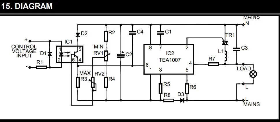
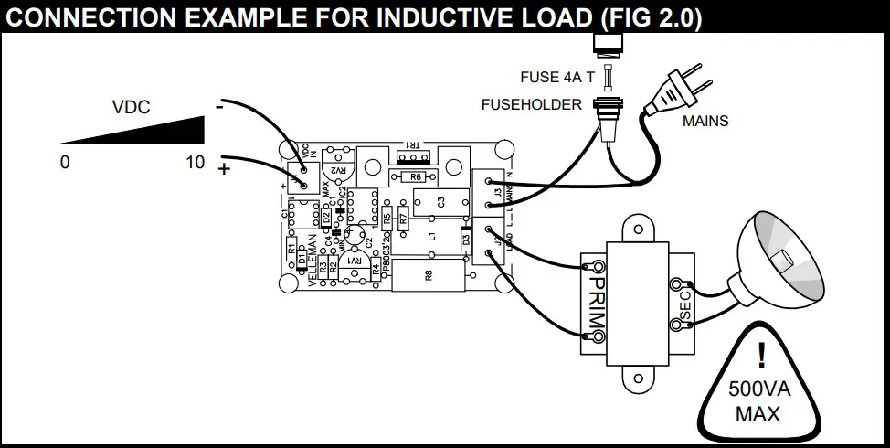
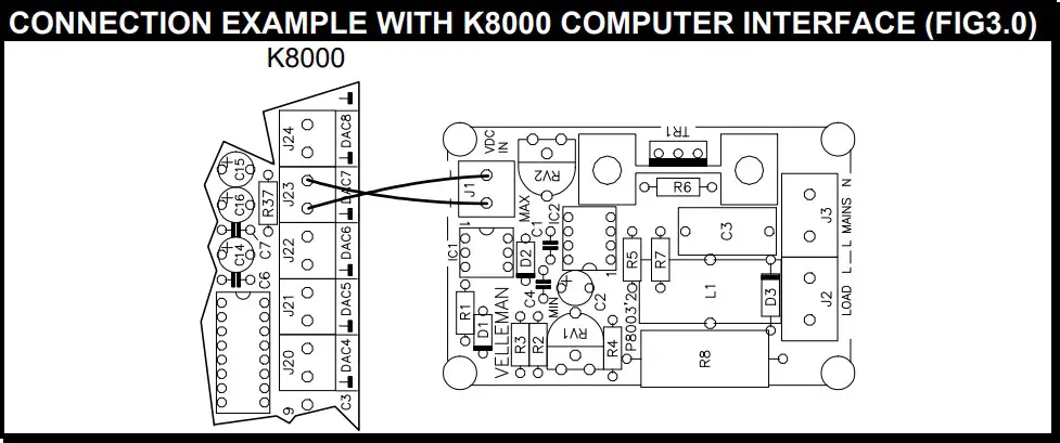
This small but handy circuit is ideal for replacing an existing dimmer or switch, in order to be able to control a lamp, set of lamps or even a moter via an adjustable DC voltage. One obvious application is control via the K8000 interface board, thanks to its optically isolated input.
Specifications :
- Operating voltages : 24, 110-125 or 220-240VAC 50/60Hz
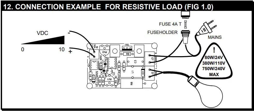
- Max. load : 3.5A (750W/220V; 380W/110V; 80W/24V)
- Control voltage : 0 to 10VDC
- Max. control current : 2.25mA at 12VDC
- Control voltage and load are optically isolated
- Isolated triac
- Dimensions : 48x74mm (1.9”x2.9”) modifications reserved
Applications :
- Control power circuits with a safe DC voltage
- Ideal for computer interfacing projects (with K8000)
- Adjust lighting, speed of collector motors, …
- Your own unique application
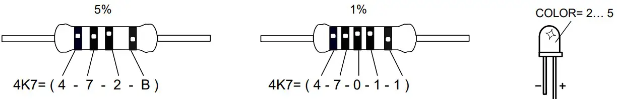
COLOUR CODE
- Black
- Brown
- Red
- Orange
- Yellow
- Green
- Blue
- Purple
- Grey
- White
- Silver
- Gold
Assembly (Skipping this can lead to troubles ! )
Ok, so we have your attention. These hints will help you to make this project successful. Read them carefully.
Make sure you have the right tools:
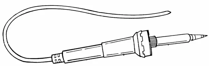
- A good quality soldering iron (25-40W) with a small tip.
- Wipe it often on a wet sponge or cloth, to keep it clean; then apply solder to the tip, to give it a wet look. This is called ‘thinning’ and will protect the tip, and enables you to make good connections. When solder rolls off the tip, it needs cleaning.
- Thin raisin-core solder. Do not use any flux or grease.
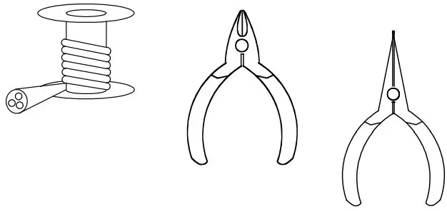
- A diagonal cutter to trim excess wires. To avoid injury when cutting excess leads, hold the lead so they cannot fly towards the eyes.
- Needle nose pliers, for bending leads, or to hold components in place.
- Small blade and phillips screwdrivers. A basic range is fine.
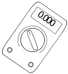
 For some projects, a basic multi-meter is required, or might be handy.
Assembly Hints :
- Make sure the skill level matches your experience, to avoid disappointments.
- Follow the instructions carefully. Read and understand the entire step before you perform each operation.
- Perform the assembly in the correct order as stated in this manual
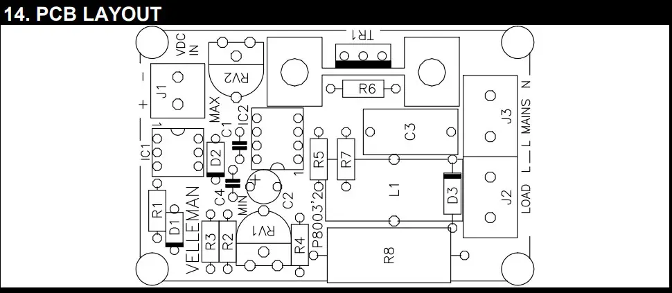
- Position all parts on the PCB (Printed Circuit Board) as shown on the drawings.
- Values on the circuit diagram are subject to changes.
- Values in this assembly guide are correct*
- Use the check-boxes to mark your progress.
- Please read the included information on safety and customer service
Typographical inaccuracies excluded. Always look for possible last minute manual updates, indicated as ‘NOTE’ on a separate leaflet.
Soldering Hints :
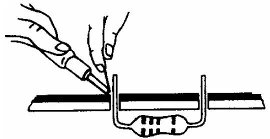
Mount the component against the PCB surface and carefully solder the leads
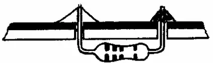
Make sure the solder joints are cone-shaped and shiny
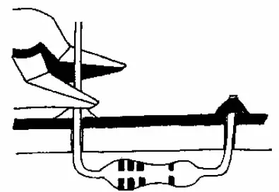
Trim excess leads as close as possible to the solder joint
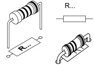
RESISTORS
- R1 : 4K7 (4 – 7 – 2 – B)
- R2 : 100K (1 – 0 – 4 – B)
- R3 : 100K (1 – 0 – 4 – B)
- R4 : 470K (4 – 7 – 4 – B)
- R5 : 1M (1 – 0 – 5 – B)
Choose operating voltage : For 24VAC :
- R6 : 15K (1 – 5 – 3 – B)
- R7 : 39K (3 – 9 – 3 – B)
For 110-125VAC :
- R6 : 100K (1 – 0 – 4 – B)
- R7 : 220K (2 – 2 – 4 – B)
For 220-240VAC:
- R6 : 220K (2 – 2 – 4 – B)
- R7 : 470K (4 – 7 – 4 – B)
DIODES (Watch the polarity!)
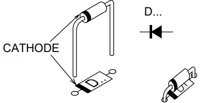
- D1 : 1N4148
- D2 : 1N4148
- D3 : 1N4007
CAPACITORS
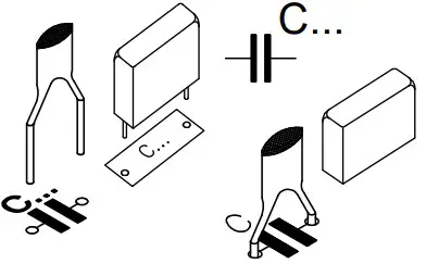
- C1 : 4n7 (472)
- C3 : 100nF/250VAC (104 – µ1)
- C4 : 100nF (104 – µ1)
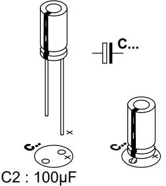
ELECTROLYTIC CAPACITORS (Watch the polarity!)
IC SOCKETS
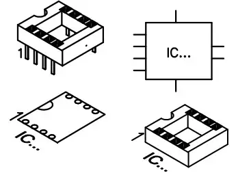
- IC1 : 6P
- IC2 : 8P
TRIM POTENTIOMETERS
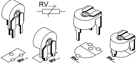
- RV1 : 220K (250K)
- RV2 : 2M (2M5)
SCREW TERMINALS
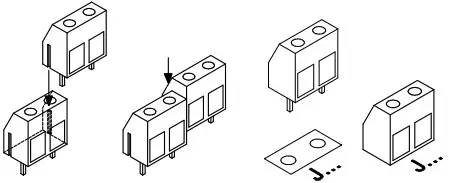
- J1 : 2P
- J2 : 2 x 2P
POWER RESISTOR
24VAC :
- R8 : 1K5 (1 – 5 – 2 – B)
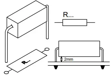
110-240VAC :
- R8 : 15K
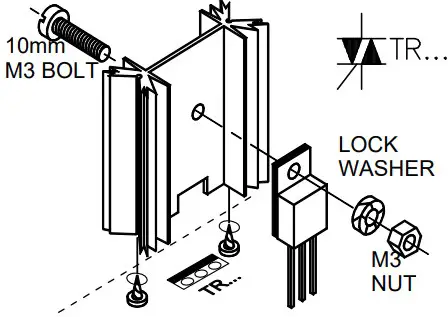
MOUNTING OF THE TRIAC
COIL
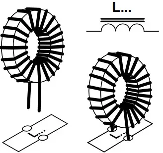
- L1 : 50µH/6A
IC’s (Watch the position of the notch)
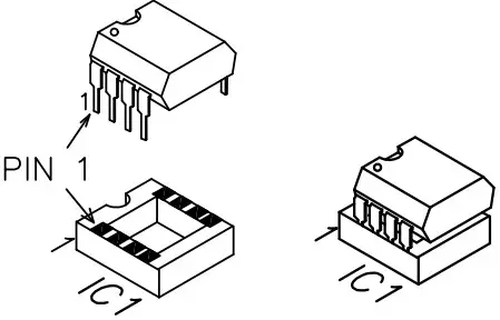
- IC1 : 4N27 or eq.
- IC2 : TEA1007 or eq.
SET UP
- Connect a digital voltmeter to the PCB in parallel with the load.
- Set both trimpots to the middle of the range of adjustment.
- Switch in the control voltage and the supply voltage.
- Set the control voltage to 0V.
- Adjust RV1 (Min) until the voltmeter reads 0V.
- Set the control voltage to maximum.
- Adjust RV2 (Max) until the voltmeter reads the maximum voltage.
- Repeat both adjustments once again.
- The circuit is now ready for use.
NOTE: In some cases it can be useful to set the minimum level such that
there is a small pre-voltage present, such as for example with stage and
theatre lighting.