Anolis UVinere Remote 1/2/4 Installation Guide
INSTALLATION WITH STANDARD BRACKETS
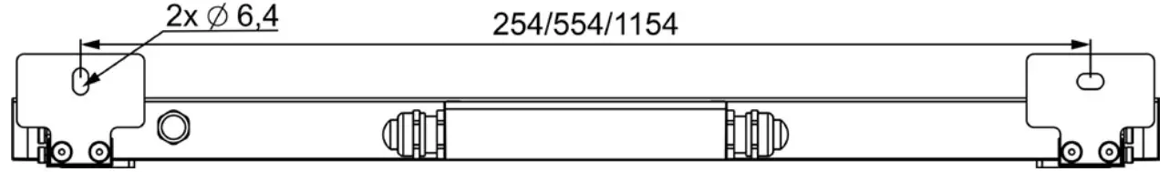
STEP 1.A
![]() Use fasteners that are appropriate for use with your mounting surface
Use fasteners that are appropriate for use with your mounting surface
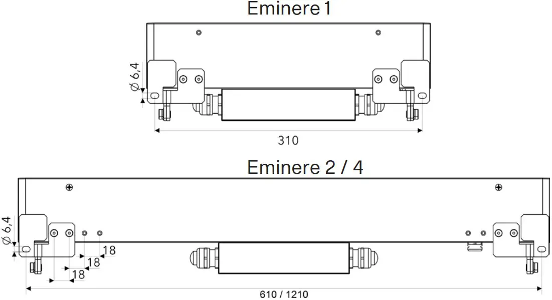
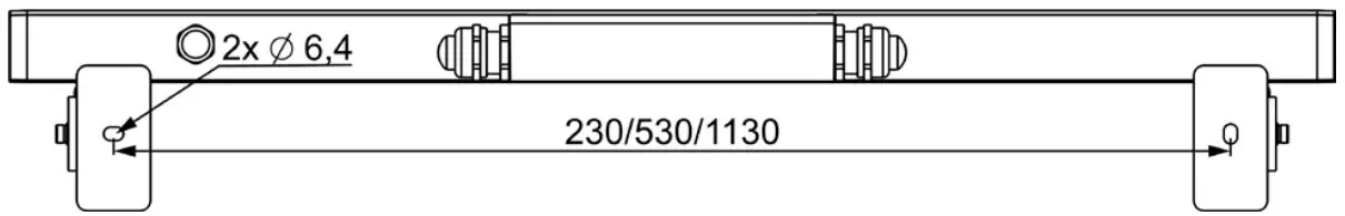
- Drill two holes into the surface according the given dimensions(Eminere Remote 1/2/4) Fasten the Eminere Remote to the surface by two washers, spring washers and screws.e

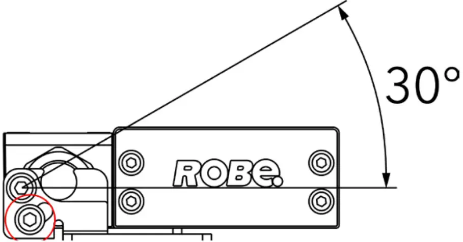
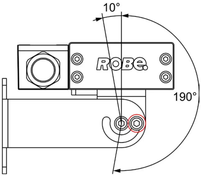
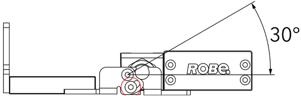
- Loosen locking screws on both sides, adjust fixture to desired position and tighten locking screwson both side.

INSTALLATION WITH WALL MOUNT BRACKETS
STEP 1.B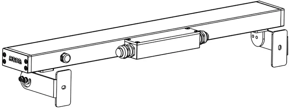
![]() Use fasteners that are appropriate for use with your mounting surface
Use fasteners that are appropriate for use with your mounting surface
- Drill two holes into the surface according the given dimensions(Eminere Remote 1/2/4) Fasten the Eminere Remote to the surface by two washers, spring washers and screws.

- Loosen locking screws on both sides, adjust fixture to desired position and tighten locking screws on both sides.

INSTALLATION WITH MOUNTING BRACKETS 100/200/300 MM
STEP 1.C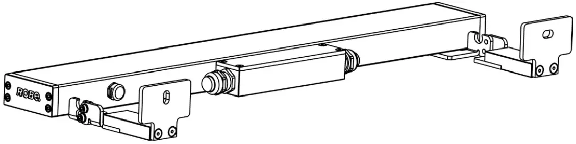
![]() Use fasteners that are appropriate for use with your mounting surface
Use fasteners that are appropriate for use with your mounting surface
- Drill two holes into the surface according the given dimensions(Eminere Remote 1/2/4) Fasten the Eminere Remote to the surface by two washers, spring washers and screws.

- Loosen locking screws on both sides, adjust fixture to desired position and tighten locking screws on both sides.

CONNECTION
- Uncover E-box.

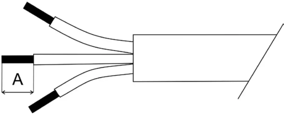
- Strip these lengths for cable connections.

A Power Connection 9mm Data Connection 9mm
Connection – colour coding
LED Unit Connection – CE Leader
| TERMINAL BLOCK | VCC | D+ | D- | 0V | GROUND |
| Colour of Wire | Red | Orange | White | Black | / |
LED Unit Connection – US leader
| TERMINAL BLOCK | VCC | D+ | D- | 0V | GROUND |
| Colour of Wire | Red | Orange | White | Black | Green/Yellow |
Wiring connection
EU leader cable shown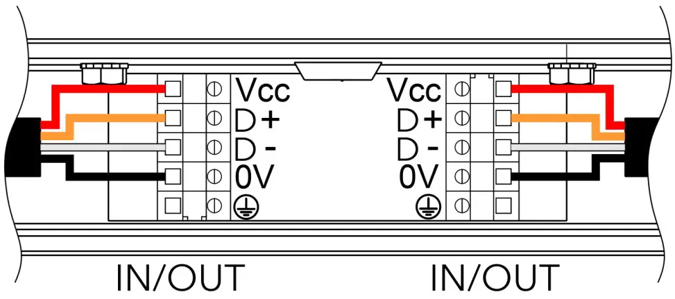
US leader cable shown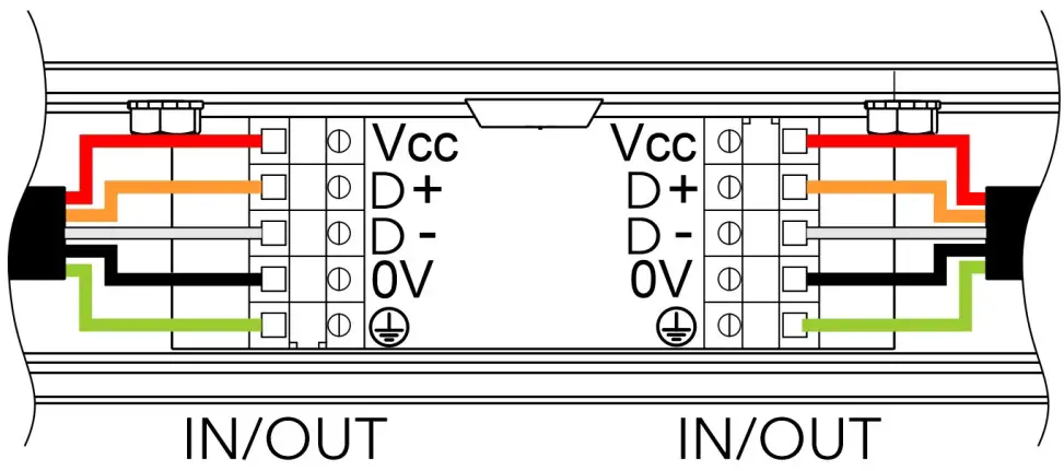
Note for E-box Remote Basic.
If the Emineres Remote UV are connected to the LED output of the E-box Remote Basic, the last Eminere Remote has to be terminated by a terminator. The terminator is a 120 Ohm resistor connected between terminals D+ and D- in the last fixture.
If both LED outputs of the E-box Remote Basic are used, both lines of Emineres Remote have to be terminated by the 120 Ohm resistor.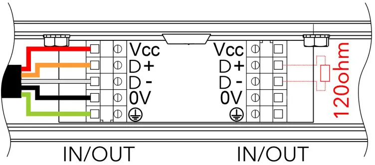
CABLE GLAND INSTALLATION
Use wrench size 24 for cable gland M20x1.5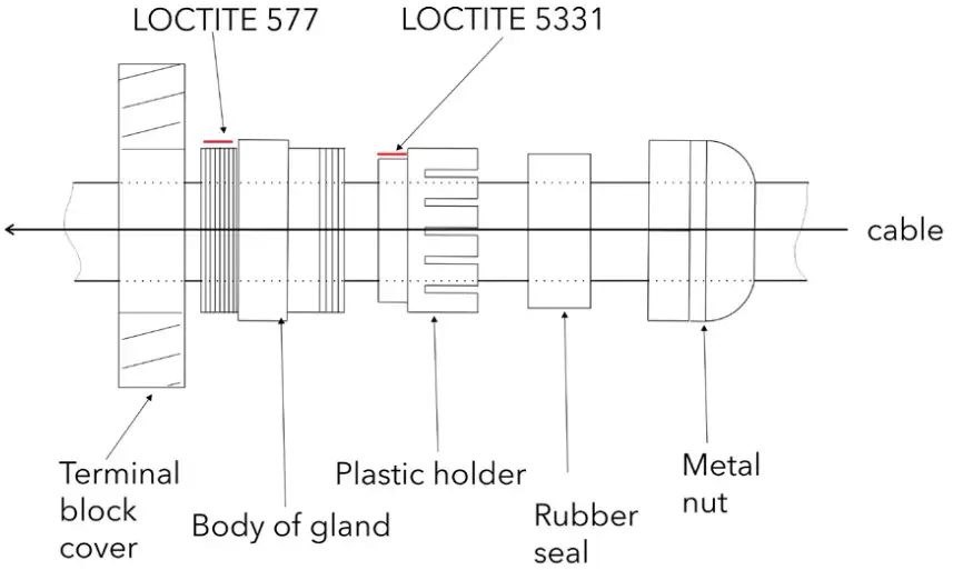
Apply Loctite 5331 thread sealant on the plastic holder and Loctite 577 thread locking compound on the gland body in the indicated locations prior to assembly.
Failure to properly install cable glands will result in failure of the water tight seal!
FILLING CONNECTION BOX WITH SYNTHETIC RESIN
After checking all connections, fill the connection box with synthetic resin. Make sure the end cap is inserted in any unused cable glands, and the earth ground wire is pulled from the junction box before filling it with resin. Read and follow all instructions stated on the resin bag prior to filling the junction box. The connection box has to be fully filled by resin.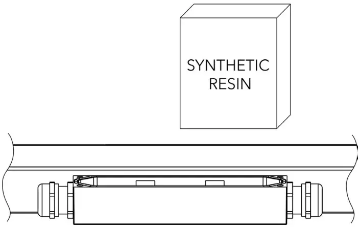
CLOSE CONNECTION BOX
Install top cover back.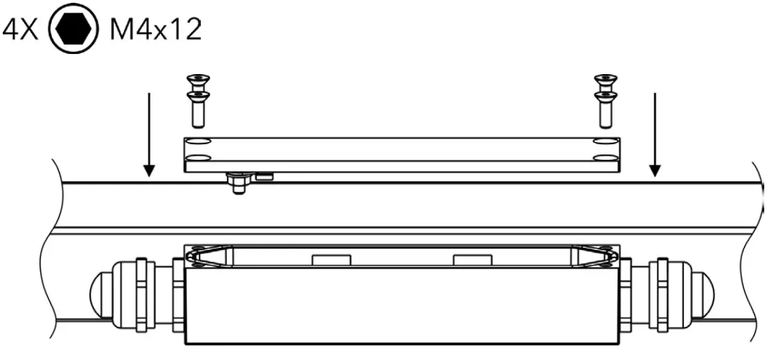
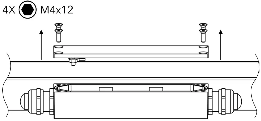
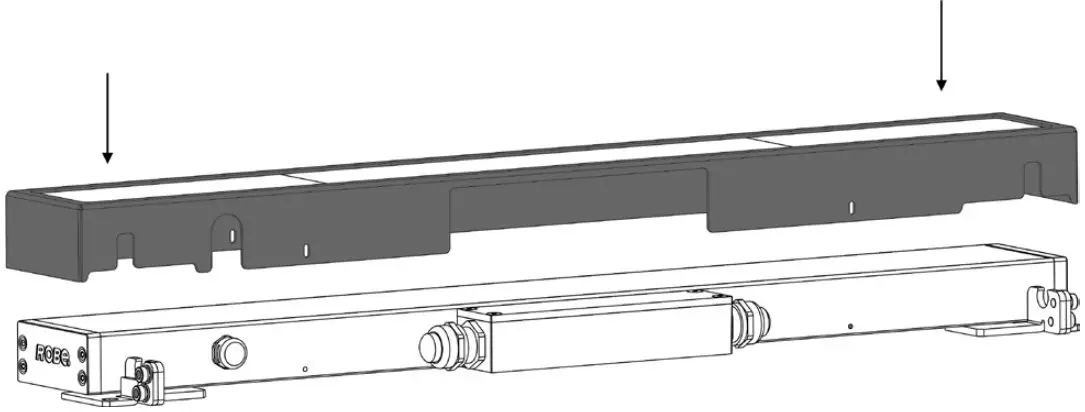
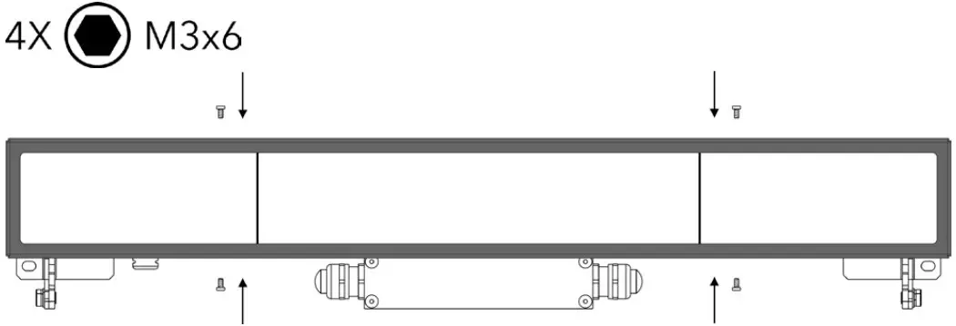
INSTALLATION OF ACCESSORIES – BLACK GLASS ADAPTOR
Eminere Remote with black glass adaptor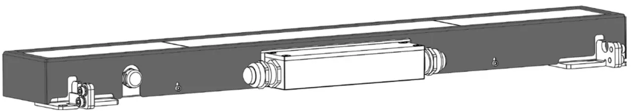
- Place the black glass adaptor onto the fixture.

- Fasten the adaptor to the fixture with 4 screws.

ROBE lighting s. r. o.
Palackeho 416
757 01 Valasske Mezirici
Czech Republic
Tel.: +420 571 751 500
E-mail: [email protected]
www.anolislighting.com