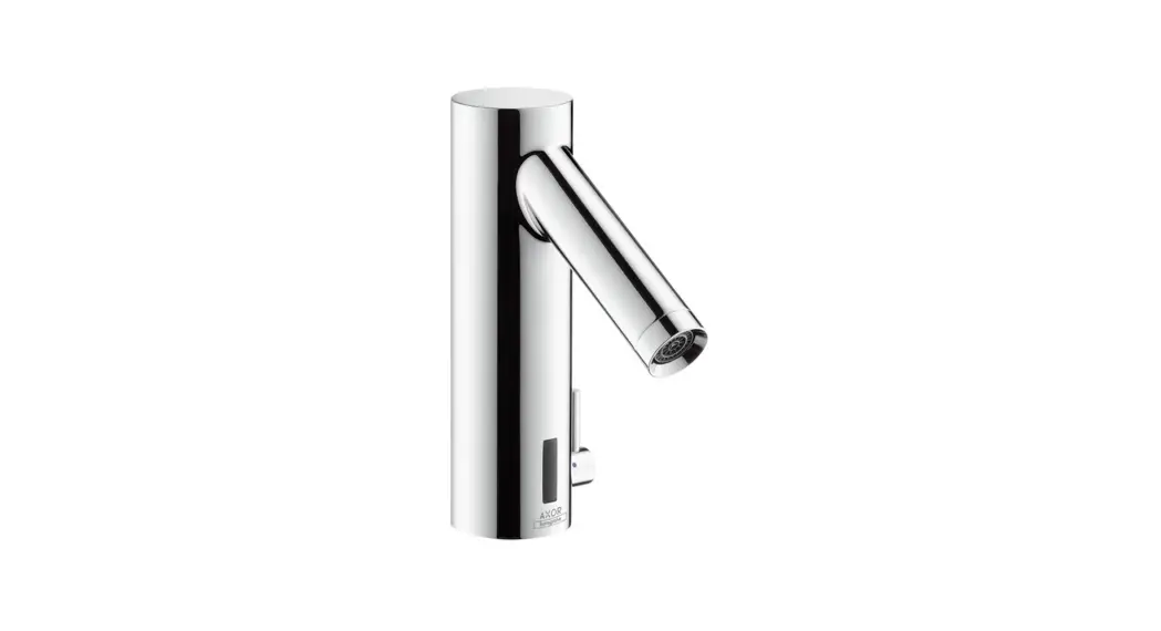
![]() Instructions for use
Instructions for use
assembly instructions
 |  |
Safety Notes
![]() Gloves should be worn during installation to prevent crushing and cutting injuries.
Gloves should be worn during installation to prevent crushing and cutting injuries.![]() The shower system may only be used for bathing, hygienic and body cleansing purposes.
The shower system may only be used for bathing, hygienic and body cleansing purposes.![]() The hot and cold supplies must be of equal pressures.
The hot and cold supplies must be of equal pressures.![]() Only the battery housing with battery or power pack supplied by Hansgrohe may be connected to the electrical connection cable of the fittings.
Only the battery housing with battery or power pack supplied by Hansgrohe may be connected to the electrical connection cable of the fittings.![]() A damaged connecting line must not be replaced. The transformer may no longer be used.
A damaged connecting line must not be replaced. The transformer may no longer be used.![]() The transformer and its mains plug may only be installed or plugged in in dry interior rooms.
The transformer and its mains plug may only be installed or plugged in in dry interior rooms.
Installation Instructions
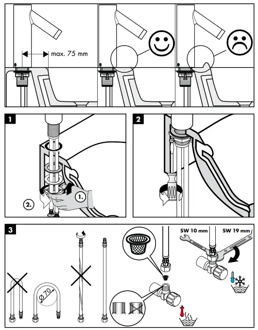
- The fitting must be installed, flushed and tested after the valid norms.
- The mesh washers must be installed to protect against incoming dirt by pipework. Incoming dirt can impair the function and/or lead to damages on functional parts of the fixture; HansGrohe will not be held liable for resulting damages.
- The mixer can not used together with a continuous flow water heater.
- The fittings must not be installed on washstands with raised edge.
- At the start of operation, or after maintenance, function of the faucet may be delayed due to reflections during adjustment of the operating distance. The faucet will automatically calibrate itself. The self-calibration will start after 10-15 minutes.
- During initial start-up and after servicing, air in the fittings can cause an unattractive jet pattern. The jet pattern is okay again after switching the jet on and off about 15 times.
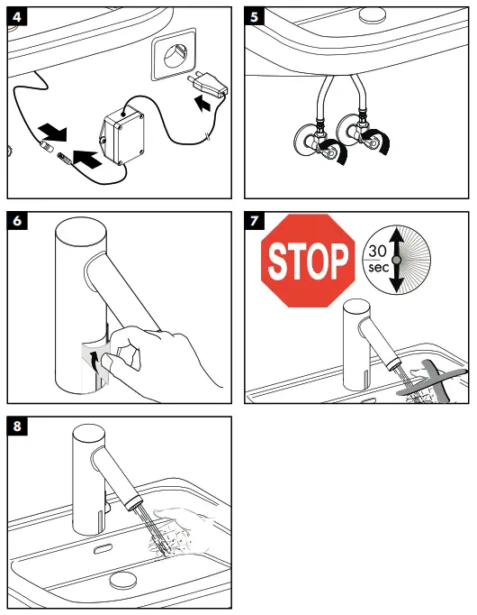
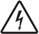 Electrical installation
Electrician![]() The installation and test work must be performed by an authorized electrician under consideration of DIN VDE 0100 part 701 / IEC 60364-7-701.
The installation and test work must be performed by an authorized electrician under consideration of DIN VDE 0100 part 701 / IEC 60364-7-701.
Electrical connection![]() Voltage supply: 230 V AC ± 10 % / 50 – 60 Hz /2 mA
Voltage supply: 230 V AC ± 10 % / 50 – 60 Hz /2 mA![]() Residual current protection system
Residual current protection system![]() The circuit must be protected via a ground fault protector (RCD / FI) with a measured differential current of ≤ 30 mA. The proper function of this fusing/protection must be checked at regular intervals.
The circuit must be protected via a ground fault protector (RCD / FI) with a measured differential current of ≤ 30 mA. The proper function of this fusing/protection must be checked at regular intervals.![]() Any work may only be carried out in a de-energized state. Here, the voltage supply must be safely separated via the main switch or mains plugs.
Any work may only be carried out in a de-energized state. Here, the voltage supply must be safely separated via the main switch or mains plugs.![]() The transformer must not be installed in protection zones 0, 1 or 2.
The transformer must not be installed in protection zones 0, 1 or 2.
Adjustment
This mixer has the following feature: background fadeout with integrated range adjustment, that means the mixer is automatically adjusted on to the local conditions (washbasin, brightness, reflection) by the sensory mechanism.
Battery operation
The indicator LED signals that the battery must be changed.
Battery voltage ≤ approx. 5.5 V:
The indicator LED in the sensor window blinks when the fitting is operated, water withdrawal continues to be possible
Battery voltage ≤ approx. 5.3 V:
The indicator LED in the sensor window lights continuously, water withdrawal is no longer possible, the battery must be replaced.
Attention! After insertion of the battery, the fitting should not be activated for approx. 30 seconds. This time is required for self-adjustment.
Power supply pack operation
For the replacement of a power supply pack, the procedure corresponds to the replacement of a battery.
Normal operation
The range of the detection area or the removal of the switch-on/off point from the fittings depends on the ambient optical conditions (for example, the shape and reflection of the washstand and the ambient light) as well as on the shape, the size, the speed and the reflection of the object that was brought into the detection area.
The detection area of the fittings or the distance of the switch-on/off point from the fittings is approx. 160 to 200 mm in normal operation.
The detection of dark (for example grey-black) objects by the fittings is inadequate because of their low reflection. The range of the detection area or the distance of the switch-on/off point can be smaller than 160 mm.
The detection of bright or reflecting objects by the fittings is very good as a result of their high reflectivity. The range of the detection area or the distance of the switching/off point can be greater than 200 mm.
Strong light sources should not shine directly on the sensor window of the fittings.
Drops of water or condensed water on the sensor window of the fittings can initiate unintended running of the water.
Range setting for infrared proximity electronics
It may be necessary to reduce the range of the infrared proximity electronics by manual mode switching when the fittings are connected to very small or highly reflecting washstands.The following two modes can be selected:
- Maximum range” (factory setting)
- Reduced range” (maximum range reduced by approx. 50 mm)The LED behind the sensor window signals which mode the fittings are currently in:
- Short blinking when the fittings are closed = “reduced range”
- No blinking when the fittings are closed = “maximum range” Perform the following steps to change from “maximum” to “reduced” range or vice versa:
- Interrupt voltage supply of the fittings for approx. 10 s (disconnect electrical plug connection between fittings and battery housing or power pack and reconnect after 10 s)
- The LED blinks to indicate the software version (e.g. blinking once = software version 1)
- When the LED lights permanently (-> calibration of infrared proximity electronics), cover sensor window completely with your hand or a white piece of paper
- Remove your hand or the paper after 20 s to 40 s
- • The LED indicates the currently activated mode by blinking: Once = “maximum range”, twice = “reduced range”
- The LED then lights permanently until the calibration of the just set range of the infrared proximity switch has completed
- When the LED goes off again, the fittings are ready for operation the sensor window is covered for a period of less than approx. 20 s or more than approx. 40 s, the already active mode is maintained and indicated by corresponding blinking of the LED (once = “maximum range”, twice = “reduced range”).
Technical Data
This mixer series-produced with Eco Smart® (flow limiter)
| Operating pressure: | max. 0,8 MPa |
| Recommended operating pressure: | 0,1 – 0,5 MPa 1,6 MPa |
| Test pressure: | (1 MPa = 10 bar = 147 PSI) |
| Hot water temperature: | max. 80 °C |
| Recommended hot water temp.: | 65 °C |
| Maximum flowing-out temperature at 50 K temperature difference and 0,3 MPa flow pressure: | 42 °C |
| Follow-on time: | 1 – 2 s |
| Automatic switching-off: | after 1 min |
| Protection class: | IP X5 |
| battery: | CR-P2 / 6 V Lithium |
| transformer: | 230 V AC ± 10 % / 50 – 60 Hz / 2 mA |
The transformer must not be installed in protection zones 0, 1 or 2.
Symbol description
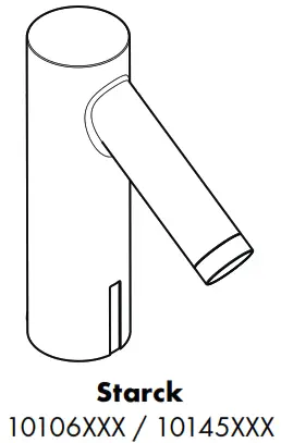
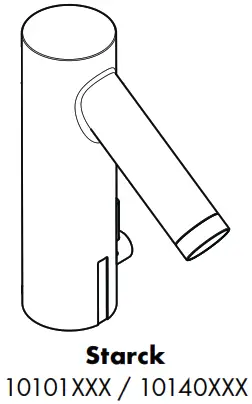
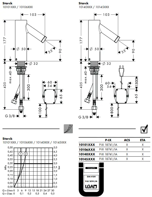
 Dimensions (see page 79)
- with Eco Smart®
- without Eco Smart®
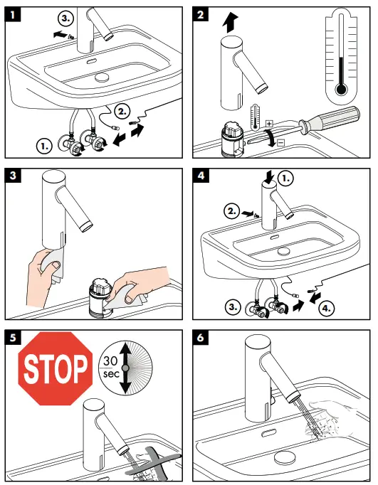
 Spare parts (see page 80)
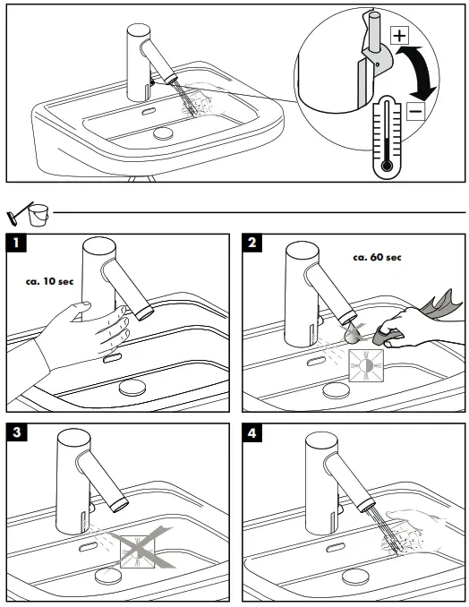
 Operation (see page 75)
 Cleaning washbasin (see page 76)
 Cleaning (see page 77) enclosed brochure
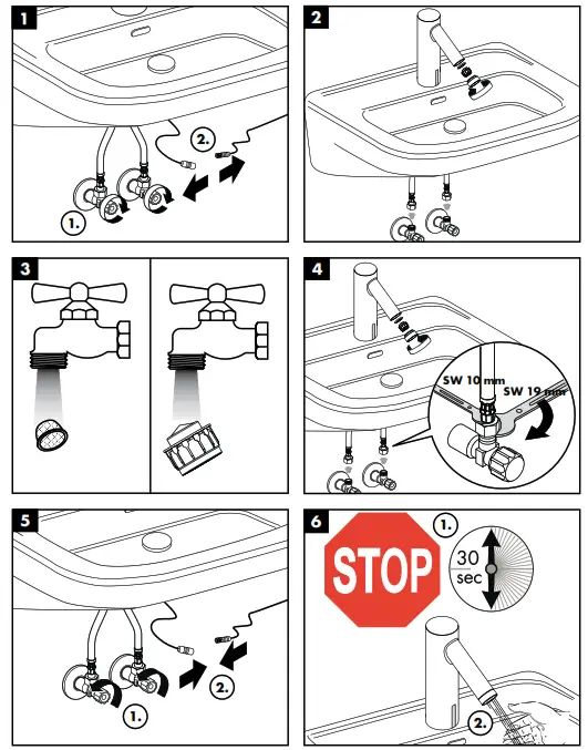
Maintenance
 The non return valves must be checked regularly according to DIN EN 1717 in accordance with national or regional regulations (at least once a year). (see page 78)
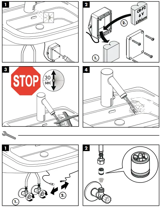
 Exchange battery (see page 78)
 Test certificate (see page 79)
 |  |
 |  |
 |  |
XXX = Colors
000 = chrome plated
800 = stainless steel optic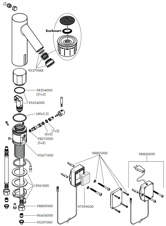
![]() Hansgrohe · Postfach 1145 · D-77761 Schiltach
Hansgrohe · Postfach 1145 · D-77761 Schiltach
Telefon +49 (0) 78 36/51-1282
Telefax +49 (0) 7836/511440
E-Mail: [email protected]
Internet: www.hansgrohe.com


