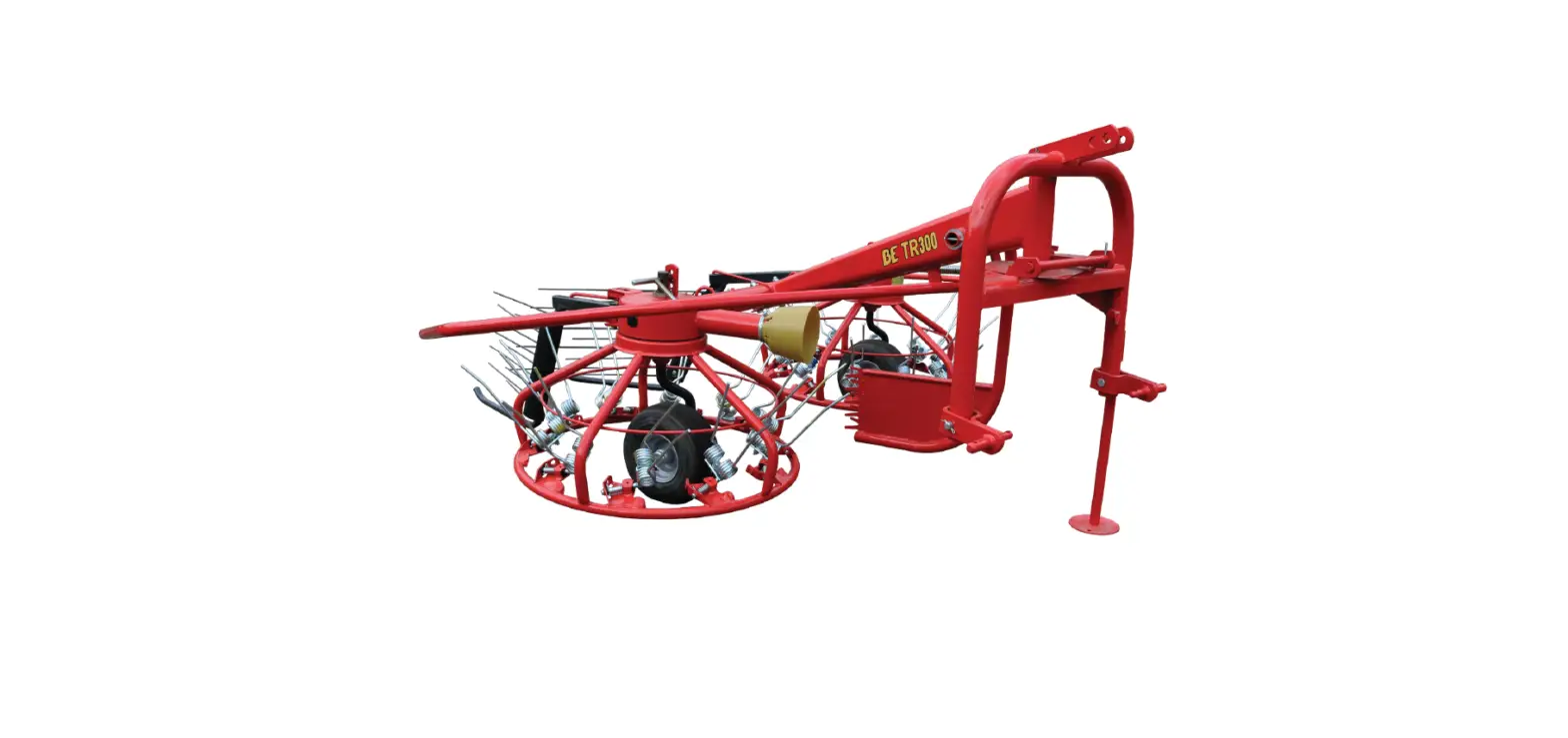
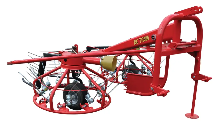
BRABER EQUIPMENT BE-TR300 Combination Tedder Rake
USED TERMS AND SYMBOLS
Specifications are subject to change without previous notice.
Directional indicators (such as “right”, “left”, “front”, “rear”, etc.) are to be interpreted when facing in direction of travel; parts are numbered from left to right.
This is also the basic position for defining the direction in connection with which:
- RH (rotation) = clockwise rotation
- LH (rotation) = counter clockwise rotation
- Rotation around a vertical axis is defined when looking from top to bottom
- Rotation around a horizontal axis almost perpendicular to the direction of travel is defined when looking from left to right.
- Rotation of bolts, nuts, hand cranks, etc. is defined when looking from the position of operation.
Unit of measurement are given both in Imperial (US) and international metric units; the metric value shall be decisive (conversion table inside fold-out page).
Abbreviations used are:
- CW = Clockwise
- CCW = Counter Clockwise
- IPL = Illustrated Spare Parts Lists
- PIN* = Product Identification No. (= machine serial no.) PSN* = Production Series No.
- = You can find this number on the identity plate of the machine.
DANGER:
When you see this safety alert heading, be alert to the danger of injury or death of men and animals.
ATTENTION:
When you see this heading, be alert to the possibility of damage to equipment, crops, buildings, etc., but to financial and/or juridical problems (warranty, product liability).
Note: This heading indicates a remark to make a job easier, better and safer.
SAFETY AND LIABILITY
Avoid accidents! Don’t learn safety the hard way! Stay Alert! Think SAFETY! Work SAFELY!
Note: Everyone must be given operating instructions before starting to operate the equipment. Pass on all safety advices to other users!
You are responsible for the SAFE operation and maintenance of your equipment. It is the operator’s responsibility to read and understand ALL safety and operating instructions in the manual and to follow these. You must ensure that you and anyone else who is going to operate, maintain or work around the unit be familiar with the operating and maintenance procedures and related SAFETY information contained
in this manual. The manual will take you step-by-step through your working day and alert you to all good safety practices that should be adhered to while operating this equipment.
- Remember, you are the key to safety. Good safety practices not only protect you but also the people around you. Make these practices a working part of your safety program. Be certain EVERYONE operating this equipment is familiar with the recommended operating and maintenance procedures and follow all safety precautions.
- Most accidents can be prevented. Do not risk injury or death by ignoring goof safety practices.
- Machines must never be tested on a tractor in an enclosed space because of the danger from exhaust fumes! Always check traffic and operational safety before putting the machine into operation.
- Adhere to the general rules of health and safety precautions besides the advice of this manual.
- The installed warning and advisory signs give important hints for a safe operation; adhering to these serves your own safety.
- Keep safety decals and signs clean and legible at all times.
- Replace safety decals and signs that are missing or have become illegible.
- If original parts on which a safety decal or sign was installed are replaced, be sure that the replacement part also displays the current decal or sign.
- When making use of public roads adhere to applicable traffic rules.
- Become acquainted with all installations and control devices as well with the function BEFORE starting operation.
- The clothing of the operator should be tight. Avoid wearing any loose clothing.
- Before beginning to drive and/or operate, check surrounding area (children!) Ensure sufficient during all operation and transport.
- No one shall drive on the machine during transport and/or operation.
- Attach accessories in accordance with mounting instructions and only to the appropriate attaching points. Special care shall be taken when (dis)mounting the machine on/off the tractor.
- When attaching/detaching the machine, place the jack stand into the corresponding position.
- Always fit front weights to the fixing points provided for that purpose.
- For road transport, bring machine in a transport position and secure it.
- Install and check transport equipment, e.g., lighting, warning devices and guards. Adhere to maximum permissible axle loads, total weights and transport dimensions.
- Never leave the operator’s seat during operation or transport.
- Moving behavior, steer ability and braking performances are influenced by mounted implements and ballast weight. Ensure sufficient braking effect and safe manageability.
- Always adapt the speed to the local conditions. When making short turns note the larger radius because of increased width or length of the combination as well as mass and inertia changes due to the other center of gravity position.
- No one should operate the machine unless all protection is installed and in functional position.
- Never stay or allow anyone to stay within the operating area.
- Never stay or allow anyone to stay within the turning and slewing area.
- Before leaving the tractor, lower the machine onto the ground, apply the parking brake, shut down the engine and remove the ignition key.
- Allow nobody to stay between tractor and machine unless the tractor is prevented from inadvertent rolling away by applied parking brake and/or placed chocks.
- Store the unit in an area away from human activity.
- Do not permit children to play on or around the stored unit. Use the provided jack supports, store in sable machine mode.
WARRANTY
In order to ensure safety. All persons working at and/or with this machine must read and understand this operation manual. Furthermore, this machine shall always be used, handled and stored in accordance with the design and construction destination (intended use) which also means:
- Exclusively work in accordance with the instructions given in the appropriate assembly, operation and repair instructions (manual) including all valid errata supplements as well as taking into account the relevant service bulletins; exclusively use correct tools and equipment being in a perfect condition.
- Strictly observe the applicable local regulations concerning safety and accident prevention, generally acknowledged and approved technical, medical and traffic rules as well the functional limitations and safety instructions stated in above mentioned technical documentation.
- Do not use any parts (spares, accessories, lubricants) other than those complying with manufacturer requirements. A part complies with manufacturer requirement when either genuine or approved by the manufacturer or when all its properties can be proven to meet with the appropriate manufacturer requirements for that very use/function.
- Only well instructed people being familiar with all possible danger shall work with or at the machine.
- The machine shall not be used nor transported unless all safety devices (cover, plates, rails, curtains, locks, etc). are correctly installed and in a perfect condition and set in the appropriate safety position. All safety decals and signs shall be legible and in the correct place.
- Unauthorized modification of or arbitrary changes on the machine or parts of it exclude any responsibility and reliability of the machine manufacturer for the consequences of that operation.
ATTENTION:
Those disregarding above mentioned rules act grossly negligent (careless) through which all manufacturer’s warranty and reliability for damages and all other consequences become extinct. The negligent person carries all risks!
Safety decals
This machine has been marked with safety decals of the new generation in accordance with ISO11684, i.e. without text. The decals are shown below
- TR 2005:
DANGER:
Stop the engine and ensure it cannot be re-started during performance of work on the machine! TR 2011:
DANGER: When three-point linkage is controlled from outside ensure no one is between tractor and machine!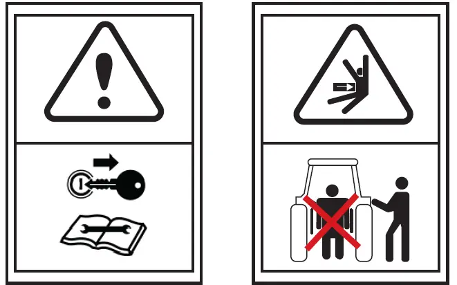
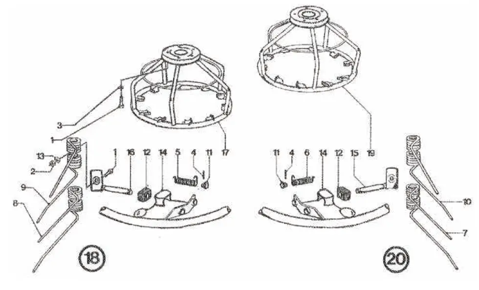
ADJUSTMENT FOR SPREADING AND TEDDING
- Tines
Put the tines in the tedding position by moving the tine shaft. Check all tines are in the correct position.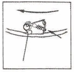
- Wheels
The wheels must be in the lower or middle position, for this operation; i.e. the machine will be in its highest position.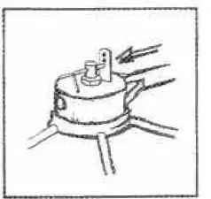
- Top Link
The top link is attached in the lower hole of the hitch-frame.
When the points of the tines exactly touch the stubble in front of the top link is correct.
At 430 RPM of the PTO the tines have reached their lowest position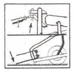
- Swath Deflectors
If required either one or both deflectors can be used to separate the swaths. This is particularly useful when working the outsides of a field.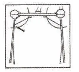
- Locking Device
Disconnect the locking device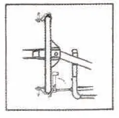
ADJUSTMENT FOR RAKING AND WINDROWING
- Tines
Place the tines in the raking position by moving the tine pivot shaft. Check all tines are in the correct position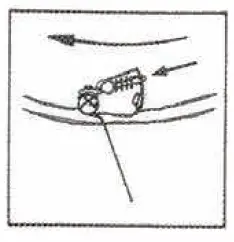
- Wheels
The wheels must be set in the upper or middle position for this operation; i.e. the machine will be in its lowest position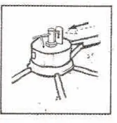
- Top Link
The top link is attached in the upper hole of the hitch-frame. When the point of the tines exactly touch the stubble in front of the rotors and the machine turns at full speed the length of the top link is correct. At 430 RPM of the PTO, the tines have reached their lowest position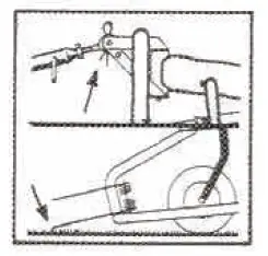
- Swath Deflectors
By placing the swath deflectors in the position shown an equal swath is built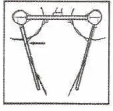
- Locking Device
Disconnect the locking device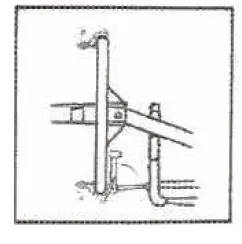
TRANSPORT POSITION
Lift the machin
During transport the locking device in the center behind the tractor (see fig. 6). Ihis also prevents the machine from sideways movement.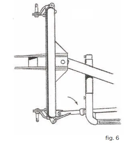
In working position, the Haybob is a trailed machine, allowing you to make left hand turns without trouble. or making right hand turns it is necessary to lort the machine on the tractor linkage.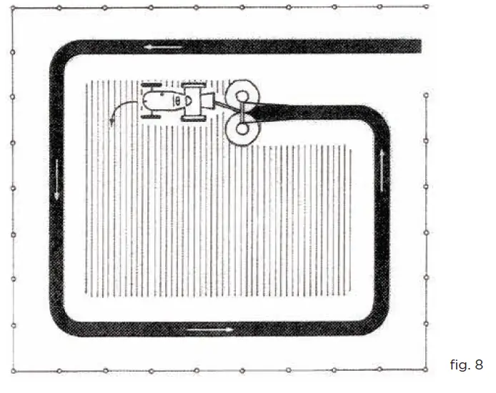
RAKING TWO SWATHS TOGETHER
When you place the swath deflectors as shown in fig. 9, the swaths are laid down close together in the first operation. These swaths are easily put together afterwards.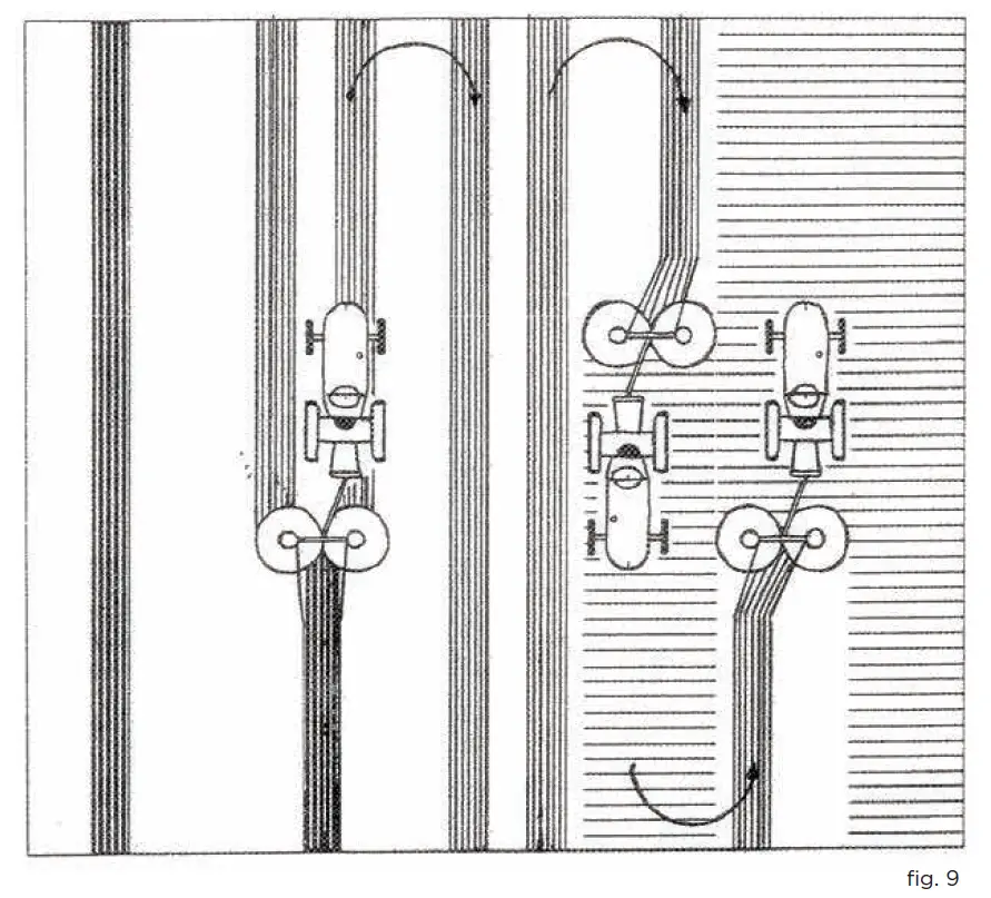
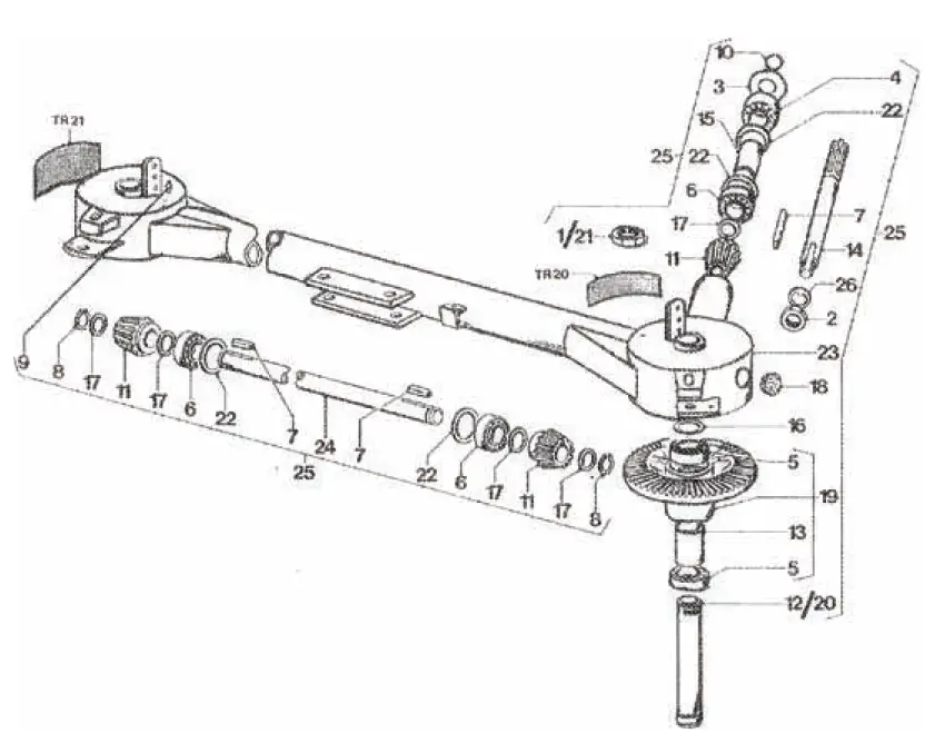
LUBRICATION AND MAINTENANCE
- Every 5 hours of work, the nipples and the inner tube of the PTO shaft must be greased.
- Every 10 hours of work, the nipples (2) on the gearboxes must be greased.
- Every 10 hours of work, the nipples (2) in the wheels must be greased.
- At the end of the season, the machine must be cleaned and made ready for the following season.
INSTRUCTIONS FOR ORDERING SPARE PARTS
Your order for spare parts should contain the following information:
- Machine-type and frame number.
- Description, part number and quantity of parts in question.
- If in doubt, send a rough sketch or pattern clearly marked with your name and address. Only original PZ spars ensure excellent quality and correct fitting.
ACCESSORIES
When using tractors, the lift capacity of which is insufficient, it may occur that the haybob cannot be raised high enough in some cases. In order to improve this, the following set can be fitted (see fig 10).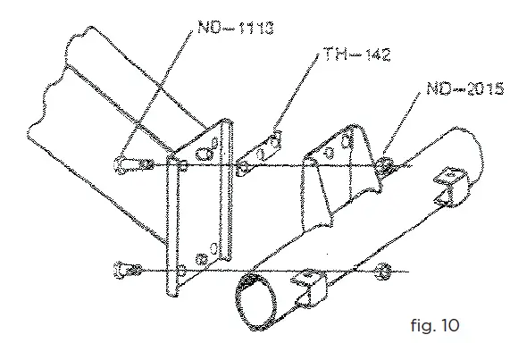
Attention: The bolt and nuts must be tightened firmly and this has to be checked after some hours of work.
EXPLODED VIEW & PARTS LIST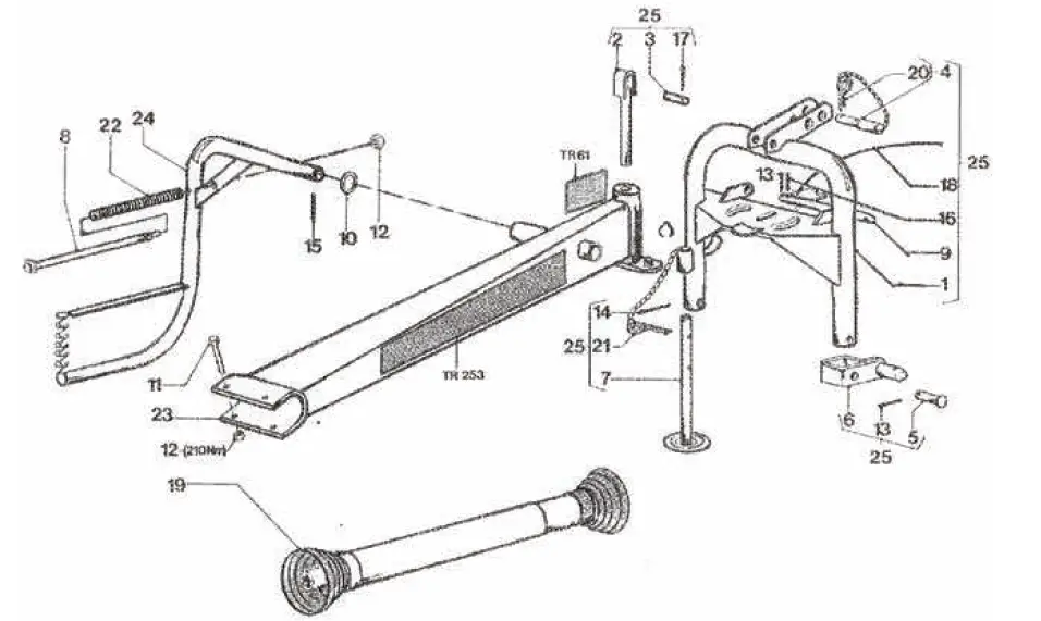
| REF | PART NO | DESCRIPTION | QTY |
| 1 | GV 037 | HITCH FRAME | 1 |
| 2 | GZ 0281 | EYE PIN | 1 |
| 3 | GZ 283V | PIN | 1 |
| 4 | HK 0028V | PIN | 1 |
| 5 | HS 182V | PIN | 2 |
| 6 | HS 0188 | HITCH BRACKET | 2 |
| 7 | HS 0200 | JACK STAND | 1 |
| 8 | HS 0210V | PIN | 1 |
| 9 | HS 0218 | LOCKING LEVER | 1 |
| 10 | MT 84V | RING | 1 |
| 11 | ND 1037V | BOLT (M16X20) | 2 |
| 12 | ND 2090V | LOCK NUT (M16) | 3 |
| 13 | ND 4020V | COTTER PIN (Ø5X35) | 3 |
| 14 | ND 4022V | COTTER PIN (Ø8X60) | 1 |
| 15 | ND 4040 | SPRING PIN (Ø8X60) | 1 |
| 16 | ND 4044V | SPRING PIN (Ø6X60) | 1 |
| 17 | ND 4055V | COTTER PIN (Ø6X35) | 2 |
| 18 | ND 9347 | CORD (Ø5X1900) | 1 |
| 19 | ND 9610 | PTO DRIVE SHAFT W2200-K32-1350-SC14 | 1 |
| 20 | PZ 25V | SPRING CLIP (Ø4) | 1 |
| 21 | PZ 199V | SPRING CLIP (Ø6) | 1 |
| 22 | PZ 281V | COMPRESSION SPRING | 1 |
| 23 | TH 0179 | SUBFRAME | 1 |
| 24 | TH 0181 | CROP DIVIDER | 1 |
| 25 | TH 00205 | HITCH FRAME ASSEMBLY | 1 |
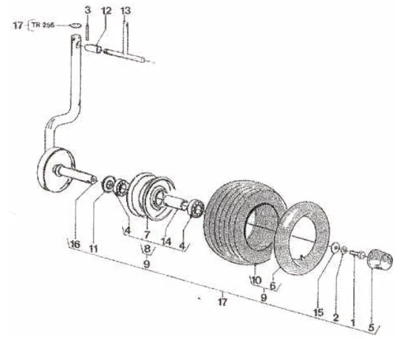
| REF | PART NO | DESCRIPTION | QTY |
| 1 | GT 37 | NUT (1-1/2” R) | 1 |
| 2 | MT 174 | NUT (M30X1.5) | 1 |
| 3 | MT 365 | DUST SHIELD | 1 |
| 4 | ND 5027 | BALL BEARING – 8207-2RS | 1 |
| 5 | ND 5036 | BALL BEARING – 6210-2Z-C3 | 4 |
| 6 | ND 5048 | BALL BEARING – 6207-2Z | 3 |
| 7 | ND 7003 | KEY (8X7X50) | 3 |
| 8 | ND 8008 | CIRCLIP – A-35 | 2 |
| 9 | ND 9004V | GREASE NIPPLE (M6X180°) | 2 |
| 10 | PZ 72 | CIRCLIP | 1 |
| 11 | TH 2 | BEVEL PINION | 3 |
| 12 | TH 041 | RH TRUNNION | 1 |
| 13 | TH 65 | SPACING TUBE | 2 |
| 14 | TH 67 | MAIN DRIVE SHAFT | 1 |
| 15 | TH 68 | SPACING TUBE | 1 |
| 16 | TH 0078 | SHIM SET (-X50, 2X58, 5) | – |
| 17 | TH 0079 | SHIM SET (-X35, 2X43) | – |
| 18 | TH 94 | PLUG (NYLON) | 1 |
| 19 | TH 00137 | BEVEL GEAR COMPL. | 2 |
| 20 | TH 0140 | LH TRUNNION | 1 |
| 21 | TH 141 | NUT (LH THREADED) 1-1/2”L | 1 |
| 22 | TH 00145 | SHIM SET (-X60X72) | – |
| 23 | TH 0173 | MAIN FRAME | 1 |
| 24 | TH 190 | DRIVE SHAFT | 1 |
| 25 | TH 00190 | MAIN FRAME COMPL. | 1 |
| 26 | VS 81 | TAB WASHER (INT) | 1 |
| REF | PART NO | DESCRIPTION | QTY |
| 1 | ND 1075V | BOLT (M12X40) | 30 |
| 2 | ND 2085V | LOCK NUT (M12) | 20 |
| 3 | ND3105V | SPRING WASHER (13MM) | 10 |
| 4 | ND 4027 | SPRING PIN ( 6X40) | 20 |
| 5 | PZ 99 | TORSION SPRING (LH) | 10 |
| 6 | PZ 100 | TORSION SPRING (RH) | 10 |
| 7 | PZ 106 | RH TINE NARROW (YELLOW) | 5 |
| 8 | PZ 107 | LH TINE NARROW (BLUE) | 5 |
| 9 | PZ 110 | LH TINE WIDE (BLUE) | 5 |
| 10 | PZ 111 | RH TINE WIDE (YELLOW) | 5 |
| 11 | TH 42 | STOP RING (NYLON) | 20 |
| 12 | TH 93 | SLEEVE (NYLON) | 20 |
| 13 | TH 100V | PLAIN WASHER (12MM) | 20 |
| 14 | TH 107 | BEARING HOUSING | 20 |
| 15 | TH 108 | RH TINE MOUNTING (YELLOW) | 10 |
| 16 | TH 0109 | LH TINE MOUNTING (BLUE) | 10 |
| 17 | TH 0203 | LH ROTOR (BLUE) | 1 |
| 18 | TH 00203 | LH ROTOR ASSY. (BLUE) | 1 |
| 19 | TH 0204 | RH ROTOR (YELLOW) | 1 |
| 20 | TH 00204 | RH ROTOR ASSY. (YELLOW) | 1 |
| REF | PART NO | DESCRIPTION | QTY |
| 1 | ND 1072V | Bolt (M12x25) | 30 |
| 2 | ND 3105V | Spring Washer (13mm) | 20 |
| 3 | ND4035V | Spring Pin ( 5×20) | 10 |
| 4 | ND 5002 | Ball Bearing (6205) | 20 |
| 5 | ND 9820V | Wheel Cap | 10 |
| 6 | ND 9779 | Tube (15×6.00) | 10 |
| 7 | ND 9781 | Rim | 5 |
| 8 | ND 9827 | Rim Assembly | 5 |
| 9 | ND 9841 | Wheel Assembly | 5 |
| REF | PART NO | DESCRIPTION | QTY |
| 10 | ND 9842 | TIRE (15X6.00-6 4PR) | 20 |
| 11 | TH 9 | DUST RING (NYLON) | 20 |
| 12 | TH 33V | SPRING SLEEVE | 20 |
| 13 | TH 062V | LOCK | 20 |
| 14 | TH 66 | Spacing Tube | 10 |
| 15 | TH 100V | Plain Washer | 10 |
| 16 | TH 0188 | Wheel Carrier | 1 |
| 17 | TH 00188 | Wheel Carrier Assembly | 1 |
BE-TR300T – Tandem Wheel Kit
| REF | PART NO | DESCRIPTION | QTY |
| 1 | 01.012.025 | Hex Bolt (12x25x1.75) | 2 |
| 2 | 121.327 | Dust Cap (52mm) | 2 |
| 3 | 51.000.013 | Tire (15”x600-6 4-Ply) | 2 |
| 4 | 51.000.014 | Tube (15”x600-6) | 2 |
| 5 | BE-TR-TANDEM | TR300 – Tandem Axel | 2 |
| 6 | ND 9827 | Rim Assy. (15”x6.00-6) | 2 |
| 7 | TH 100V | Washer (29x12x5) | 2 |
| 8 | TH 9 | Dust Ring | 2 |
- Tandem Wheel Kit not illustrated in parts breakdown.
- Tandem Wheel Kit uses components from existing rake
| REF | PART NO | DESCRIPTION | QTY |
| 1 | JH 66 | 2 | |
| 2 | ND 1007 | 6 | |
| 3 | ND 1055V | 4 | |
| 4 | ND 1063 | 4 | |
| 5 | ND 2064V | 10 | |
| 6 | ND 2091V | 4 | |
| 7 | ND 3009V | 2 | |
| 8 | ND 4025V | 2 | |
| 9 | PZ 114 | 10 | |
| 10 | PZ 115 | 2 |
| REF | PART NO | DESCRIPTION | QTY |
| 11 | PZ 300V | Compression Spring | 2 |
| 12 | PZ 301V | Circlip | 2 |
| 13 | TH 115 | LH Spring Holder | 1 |
| 14 | TH 116 | RH Spring Holder | 1 |
| 15 | TH 125 | Shield | 2 |
| 16 | TH 0208 | RH Deflector Frame | 1 |
| 17 | TH 00208 | RH Deflector Assy | 1 |
| 18 | TH 0209 | LH Deflector Frame | 1 |
| 19 | TH 00209 | LH Deflector Assy | 1 |
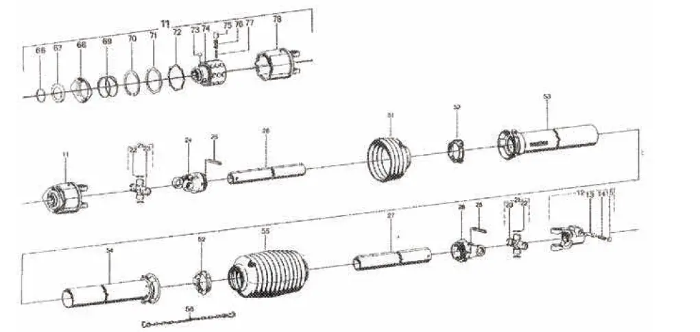
| REF | PART NO | DESCRIPTION | QTY |
| 11 | 55.210.03 | Star Ratchet Clutch Compl. (K33-R-2200-1 3/8” (6) M=700Nm) | 2 |
| 12 | 20.10.00 | Quick-Disconnect Yoke Compl. AG 2200-1 3/8” (6) | 6 |
| 13 | 85.01.12 | Quick-Disconnect Pin | 4 |
| 14 | 66.01.49 | Compression Spring | 4 |
| 15 | 16.11.22 | Washer | 10 |
| 21 | 20.00.00 | Cross Bearing Kit Compl. | 4 |
| 22 | 62.23.00 | Retaining Ring (24×1.5) | 2 |
| 23 | 63.22.01 | Grease Nipple | 2 |
| 24 | 20.11.00 | Inboard Yoke (RG 2200-0V) | 10 |
| 25 | 61.05.04 | Spring Type Straight Pin (10×65 DIN 1481) | 2 |
| 26 | 75.11.16* | Profile Tube 39.4in. lg. (Ov: L=1000mm) | 2 |
| 27 | 75.15.16* | Profile Tube 39.2in. lg. (1: L=995mm) | 2 |
| 28 | 20.12.00 | Inboard Yoke (RG 2200-1) | 1 |
| 51 | 84.03.06 | Guard Cone | 1 |
| 52 | 82.83.06 | Bearing Ring | 2 |
| 53 | 80.37.03* | Outer Guard with Collar 37in. lg. (L=940mm) | 1 |
| REF | PART NO | DESCRIPTION | QTY |
| 54 | 80.36.03* | Inner Guard Tube with Bearing Housing 37in. lg. (L=940mm) | 2 |
| 55 | 84.02.101 | Guard Cone | 2 |
| 56 | 82.36.03 | Safety Chain | 1 |
| 66 | 62.07.00 | Snap Ring (SP 42 DIN 5417) | 1 |
| 67 | 16.20.14 | Backup Ring | 2 |
| 68 | 65.03.05 | Lock Collar | 1 |
| 69 | 66.01.46 | Compression Spring | 1 |
| 70 | 62.15.00 | Retaining Ring (80×2.5) | 1 |
| 71 | 55.15.00 | Supporting Ring | 1 |
| 72 | 55.17.11 | Sealing Ring | 1 |
| 73 | 64.01.02 | Ball (1/2”V DIN 5401) | 2 |
| 74 | 55.14.18 | Hub (1-3/8” (6) | 1 |
| 75 | 55.01.03 | Cam | 1 |
| 76 | 66.01.04 | Compression Spring; Outer | 1 |
| 77 | 66.01.05 | Compression Spring; Inner | 1 |
| 78 | 20.31.03 | Clutch Housing | 1 |
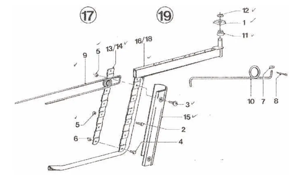
| REF | PART NO | DESCRIPTION | QTY |
| 1 | GZ 154 | Brace | 3 |
| 2 | GZ 00156 | Lamp Support Assembly | 3 |
| 3 | GZ 0252 | Lamp Support | 3 |
| 4 | ND 1068V | Bolt (M10x35) | 1 |
| 5 | ND 1137V | Bolt (M8x50) | 3 |
| 6 | ND 1269 | Bolt (M12x70) | 2 |
| 7 | ND 2084 | Lock Nut (M10) | 1 |
| 8 | ND 2085V | Lock Nut (M12) | 2 |
| 9 | ND 2091V | Lock Nut (M12) | 3 |
| 10 | TH 0194 | LH Guard Rail | 1 |
| 11 | TH 00194 | Protection Compl. | 1 |
| 12 | TH 0195 | RH Guard Rail | 1 |
[email protected]
PHONE: 604-850-7770
FAX: 604-850-7774
TOLL-FREE PHONE: 1-877-588-3311
TOLL-FREE FAX: 1-800-665-7334


