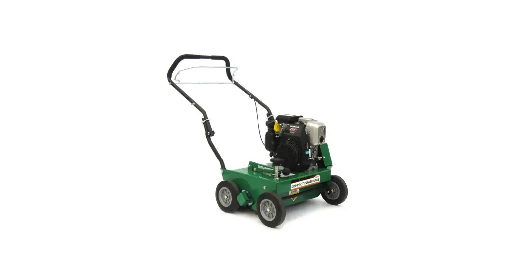
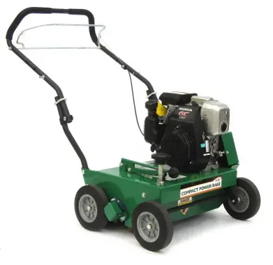
![]() CR550HC Compact Power Rake
CR550HC Compact Power Rake
Owner’s Manual
Accessories
SLICING REEL
A complete voicing reel four. 20″ wide for use in great require cutting, and assisting in law overseeding projects.
P/N 350252
SLICING BLADE
A full set of twenty blades for replacement. Includes 40 new capscrews, and lock nuts for replacement installation.
P/N 350187
SPACER BUMPERS
A complete replacement set. 44 of 1/2″ spacer bumpers and 4 of 1/4″ spacer bumpers
P/N 350258
DRIVE BELT
Original Equipment drive belt for your CR.
P/N 350207
FLAIL BLADES
A complete replacement set. 30 of our high-quality flail blades for your CR. Includes 8 new lock clips for replacement installation.
P/N 350251
FLAIL SHAFTS
A full set of four shafts for replacement. includes 8 new locclips replacement installations. NOTE: We recommend placing the shaft when you replace lails.
P/N 350185
Original Instructions
IMPORTANT- READ CAREFULLY BEFORE USE AND KEEP FOR FUTURE REFERENCE.
ABOUT THIS MANUAL
THANK YOU for purchasing a BILLY GOAT ® CR Power Rake. Your new machine has been carefully designed and manufactured to provide years of reliable and productive ervice. This manual provides complete operating and maintenance instructions that will help to maintain your machine in top running order. Read this manual carefully before assembling, operating, or servicing your equipment.
SPECIFICATIONS
| R550H | CR550HC | CR550HCEU | |
| Engine: HP | 5.4 (4.0kW) | 5.0 (3.73 kW) | 5.0 (3.73 kW) |
| Engine: Model | X160UTQX2 | GC160AQHA | GC160AQHL |
| Engine: Type | HONDA OHC | HONDA OHC | HONDA OHC |
| Engine: Fuel Capacity | 3.8 qt (3.6L) | 2.1 qt (2.0 L) | 2.1 qt (2.0 L) |
| Engine: Oil Capacity | 0.63 qt (0.6L) | 0.63 qt. (0.6 L) | 0.63 qt. (0.6 L) |
| Total Unit Weight: | 125# (56.8 kg) | 125# (56.8 kg) | 125# (56.8 kg) |
| Max. operating slope | 20o | 20o | 20o |
| In accordance with 2000/14/EEC standards | 99 dB(a) | 99 dB(a) | 99 dB(a) |
SAFETY
WARNING ![]()
This product can expose you to chemicals including gasoline engine exhaust, which is known to the State of California to cause cancer, and carbon monoxide, which is known to the State of California to cause birth defects or other reproductive harm. For more information go to www.P65Warnings.ca.gov.
Read the safety rules and follow them closely. Failure to obey these rules could result in loss of control of the unit, severe personal injury or death to you, or bystanders, or damage to property or equipment.
INTENDED USE
This machine is designed for removing thatch from your lawn, renovating of existing lawns, and assisting in overseeding operations. The machine should not be used for any other purpose than that stated above.
DO NOT operate if excessive vibration occurs. If excessive vibration occurs, shut the engine off immediately and check for the damaged or worn reel, loose pulley bolts or set screws, loose engine or lodged foreign objects. (See troubleshooting section on page 9).
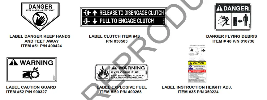
INSTRUCTION LABELS
The labels shown below were installed on your BILLY GOAT ® CR Power Rake. If any labels are damaged or missing, replace them before operating this equipment. Item numbers from the Illustrated Parts List and part numbers are provided for convenience in ordering replacement labels. The correct position for each label may be determined by referring to the Figure and Item numbers shown.
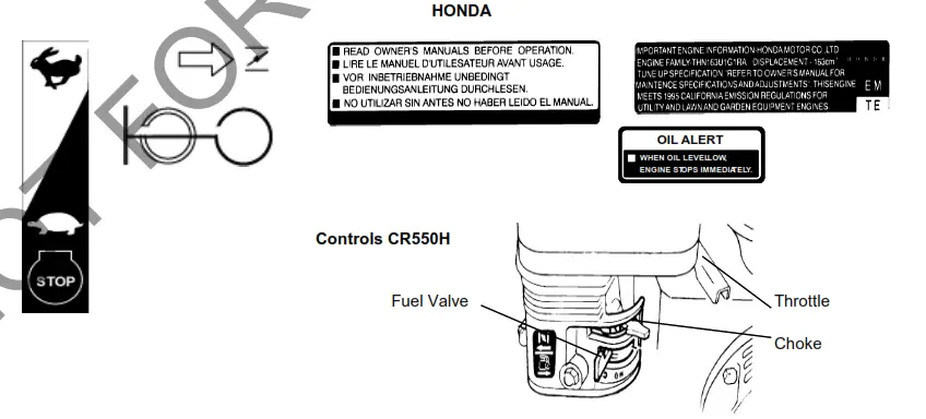
ENGINE LABELS/CONTROLS
PACKING CHECKLIST
NOTE: Items in ( ) can be referenced in the Parts Illustration and Parts List on pages 10-11.
Your Billy Goat Power Rake is shipped from the factory in one carton, completely assembled.![]() READ all safety instructions before assembling the unit.
READ all safety instructions before assembling the unit.
TAKE CAUTION when removing the unit from the box the Handle Assembly is attached and folded over.
PARTS BAG & LITERATURE ASSY
Warranty card P/N- 80102772, Owner’s Manual P/N-350245, Declaration of Conformity P/N-100504, General Safety and
Warnings manual P/N-100295, and Literature CR Accessories 350246.
- Boxing Parts Checklist
- Honda Engine Manual
- Literature Assy P/N-350243
ASSEMBLY
NOTE: Items in ( ) can be referenced in the Parts Illustration and Parts list on pages 10-11.
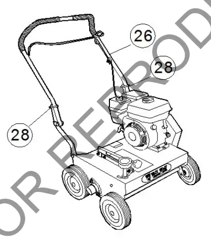
- UNFOLD the upper handle (item 26) and slide handle lock loops (item 28) into place to secure the upper handle to the lower.
- CHECK engine oil level and fill to the proper level with engine manufacturer’s recommended grade of oil. Move the height adjustment lever to the down position, to level engine during checking. See engine manufacturer’s instruction manual.
- CONNECT spark plug wire.
OPERATION
STARTING ENGINE
See engine manufacturer’s instructions for type and amount of oil and gasoline used. The engine must be level when checking and filling oil and gasoline.
FUEL VALVE: Move the fuel valve to the “ON” position (when provided on the engine).
STOP SWITCH: Located on the engine. “slow/stop” position.
CHOKE: Operated with choke lever on side of the engine.
THROTTLE: Controlled by throttle lever on the motor.
If your unit fails to start, check the troubleshooting section on page 9 and also see the engine manual.
SLICING OPERATION
NOTE: NEVER PARK THIS UNIT ON A SLOPE OF ANY KIND. Always keep the reel in the up position when parking the unit.
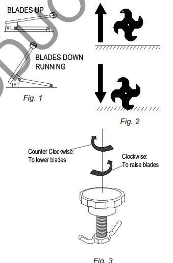
BLADE POSITION & DEPTH CONTROL LEVER: The blades can be raised or lowered into the ground by a height adjustment lever on the engine base. The resulting blade depth can be adjusted higher or lower. (See Fig. 1 & 2)![]() ADJUSTING BLADE DEPTH: The depth of the blades can be raised or lowered by rotating the knob on the top of the adjustment lever. The blades are lowered by rotating the knob counter-clockwise and raised by rotating the knob clockwise. The relative depth of the blades can be gaugedy sing the depth scale located on the right front corner of the engine base. (See Fig. 3)
ADJUSTING BLADE DEPTH: The depth of the blades can be raised or lowered by rotating the knob on the top of the adjustment lever. The blades are lowered by rotating the knob counter-clockwise and raised by rotating the knob clockwise. The relative depth of the blades can be gaugedy sing the depth scale located on the right front corner of the engine base. (See Fig. 3)
FOLDING HANDLE: This unit is equipped with a folding upper handle for easier storage and transportation. The handle can be folded by sliding the handle lock loops up item 28). This releases the upper handle, allowing it to be folded over the unit.![]() HANDLING & TRANSPORTING: This unit requires two people to lift it. With the handle in the folded position, lift holding the lower handle and belt/shaft guard one on each side of the machine. Secure the machine in place during transport. Never lift the machine while the engine is running.
HANDLING & TRANSPORTING: This unit requires two people to lift it. With the handle in the folded position, lift holding the lower handle and belt/shaft guard one on each side of the machine. Secure the machine in place during transport. Never lift the machine while the engine is running.
STORAGE: Never store engine indoors or in enclosed poorly ventilated areas with fuel in tank, where fuel fumes may reach an open flame, spark or pilot light, as on a furnace, ater heater, clothes dryer or other gas appliance. If the engine is to be unused for 30 days or more, prepare as follows:
Remove all gasoline from the carburetor and fuel tank to prevent gum deposits from forming on these Fig. 3![]() RAKING OPERATION
RAKING OPERATION
SET DEPTH: With the engine off, set the raking depth so that the blades just touch on a flat surface (i.e. driveway, or sidewalk).
ENGAGE BLADES: Pull back on the bail on the operator’s handle.
NOTE: When engaging the blades in heavy load conditions, i.e. heavy thatch or very uneven turf, push down on the operator’s handle lifting the front wheels slightly. Engage the blades.![]() Slowly lower the unit into the turf.
Slowly lower the unit into the turf.
RAKE: Rake a small test area and examine the results. Thatch should be removed and deposited on top of the healthy grass. If excessive damage occurs to healthy grass, adjust the blade depth to decrease damage. Continue raking the yard, working in one direction (i.e. north-south, or east-west).
NOTE: If a large drop in engine RPM occurs, or the unit ulls you forward and bounces during operation, the blade depth is set too low.![]() REMOVE THATCH: After raking, a layer of thatch will be deposited over the top of the lawn. This thatch must be removed prior to any fertilizing, seeding, or watering of the lawn. We suggest the use of a lawn vacuum or wheeled blower for the collection and removal of the thatch.
REMOVE THATCH: After raking, a layer of thatch will be deposited over the top of the lawn. This thatch must be removed prior to any fertilizing, seeding, or watering of the lawn. We suggest the use of a lawn vacuum or wheeled blower for the collection and removal of the thatch.
VERTI-CUTTING OPERATION
SET DEPTH: With the engine off, set the raking depth so that the blades just touch on a flat surface (i.e. driveway, or sidewalk).
ENGAGE BLADES: Pull back on the bail on the operator’s handle. NOTE: When engaging the blades in heavy load conditions (i.e. heavy thatch, or very uneven turf), push down on the operator’s handle lifting the front wheels slightly. Engage the blades. Slowly lower the unit into the turf.
SLICE: Verti-cut a small test area and examine the results. Some thatch and cut stems should be removed and deposited on top of the healthy grass. Grass runners should be cut nd ready for removal. If excessive damage occurs to healthy grass, adjust the blade depth to decrease damage. Continue raking the yard, working in one direction (i.e. north-south, or east-west).
NOTE: If a large drop in engine RPM occurs, or the unit pulls you forward and bounces during operation, the blade depth is set too low. REMOVE HATCH/STEMS: After verti-cutting, a layer of thatch and cut stems will be deposited over the top of the lawn. We suggest the use of a lawn vacuum or wheeled blower for the collection and removal of the thatch/stems.
*****TIPS*****
MOW
Mow the lawn to its normal cut height.
DRY
Be sure the grass is dry. Wet conditions can cause increased damage to healthy grass.
INSPECT
Check the lawn before beginning work. Remove all rocks, wire, string, or other objects that can present a hazard during work prior to starting.
IDENTIFY
Mark all fixed objects to be avoided during work, such as sprinkler heads, water valves, buried cables, or clothesline anchors, etc.
THATCH
Thatch is a dense layer of dead grass, clippings, and roots that builds up over time at the base of the lawn preventing air, water, and fertilizer from reaching the soil. This can cause shallow root development and make a lawn more susceptible to drought and disease. Thatch also provides an ideal environment for insects to hide and multiply. Periodic removal of thatch will keep your lawn= in good health.
HEAVY THATCH
Lawns with an excessive amount of thatch will require multiple treatments for effective removal. Trying to remove excessive thatch (greater than 3/4″[19 mm] deep) in one treatment will damage or destroy the living part of the lawn. It is best to remove heavy thatch in seasonal treatments (i.e. spring, and fall).
CHECK
Before beginning, it is best to evaluate the condition of the lawn by cutting one or more core samples from the area to be treated. A core can be cut using a piece of pvc, or metal pipe. Hammer the pipe into the ground, remove it, push the core out of the pipe and inspect it to determine the depth of thatch in your yard.
SLOPES
Rake slopes across not up and down the slope. This is much easier and safer for the operator and is better for the lawn. Raking across will help to reduce runoff during watering and allow the sloped ground to hold more seed, fertilizer, and water. The units maximum operating slope is 35% or 19°.
DEPTH
The wide range of depth adjustments on your unit is provided to allow for blade wear. Setting the reel deeper will not produce better, or quicker results. The flail reel is intended to be set so it just touches the surface on flat ground. The slicing reel should be set even with the ground for verti-slicing work, and set to a maximum 1/2″ depth for overseeding jobs. Setting the reel deeper than this will only result in premature wear on the unit (i.e. failed belt). If you desire to work the ground deeper than the above guidelines allow, it should be done gradually in multiple passes.
MAINTENANCE
PERIODIC MAINTENANCE
NOTE: Items in ( ) can be referenced in the Parts Illustration and Parts List on pages 10-11. Periodic maintenance should be performed at the following intervals:
| Maintenance Operation | Every Use (daily) | Every 25 Hours |
| Inspect for loose, worn or damaged parts | l | |
| Check engine oil | l | |
| Inspect belt | l | |
| Engine (See Engine Manual) | ||
| Grease reel bearings | l | |
| Inspect and clean engine air filter | l | |
| Oil height adjustment linkage | l |
FLAIL BLADE WEAR
- Wait for the engine to cool and disconnect the spark plug.
- Close the fuel valve on the engine. (Honda only)
- Lean unit back onto lower handles and secure in place.
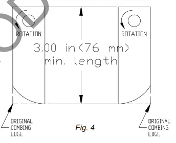
- Inspect blades for wear, and immediately replace any bent or cracked blades. Measure the overall length of the blade. (See Fig. 4)
- If blades measure less than 3.0″(76 mm) in overall length, they must be replaced. NOTE: We recommend replacing all the flails at once.
SLICING BLADE WEAR
- Wait for the engine to cool and disconnect the spark plug.
- Close the fuel valve on the engine. (Honda only)
- Lean unit back onto lower handles and secure in place.
- Inspect blades for wear, and immediately replace any bent or cracked blades. Measure the overall length of the blade from the center of the attachment bolts to the tip of the worn blade.
- If blades measure less than 3.0″(76 mm) they must be replaced. NOTE: We recommend replacing all the blades at once.
ROTATING FLAIL REEL END TO END
To maximize flail blade life and performance, the reel can be rotated end to end periodically to provide a fresh lead cutting edge.
Takes approx. 20 min. and requires two 1/2″ socket wrenches with an extension bar.
- Wait for the engine to cool and disconnect the spark plug.
- Close fuel valve on the engine.
- Lean unit back onto lower handles and secure in place.
- Remove six screws (item 65) holding the belt and shaft guards (item 21 & 22) in place. It is necessary to lower the height adjust lever to reach the locknuts on the guards. Remove the guards.
- Remove the drive belt (item 9) by “walking” it out of the groove on the reel pulley (item 2).
- Remove the four lock nuts (item 47) and washers (item 35) holding the bearings (item 23) to the frame of the unit.
- The reel (item 6) is now free from the machine. Slide the reel down and out of the machine.
- Remove the capscrew (item 58), lock washer (item 57), reel pulley (item 2), key (item 75), and reel spacer (item 10) from the end of the reel.
- Rotate the reel end to end, and re-install these items on the opposite end of the reel.
- Re-install the reel in reverse order of removal. Re-install the guards in reverse order of removal
DRIVE BELT REPLACEMENT
NOTE: Takes approx. 10 min. and requires a 3/8″ socket wrench with extension.
- Wait for the engine to cool and disconnect the spark plug.
- Remove six self-tapping screws (item 65) holding the belt guard (item 21 & 22) in place. Remove the guard.
- Remove the belt (item 9) by rotating the reel pulley (item 2) and walking it out of the groove. Discard old belt
- Install the new belt using same procedure to walk the belt into the groove.
- With new belt installed, pull bail rod back to engaged position and measure the extension of the idler spring. Spring should stretch 1″ to 1.25″ (25-32 mm) with bail engaged. Adjust clutch cable as necessary to achieve this extension.
- Re-install the belt guard.
TROUBLESHOOTING
| Problem | Possible Cause | Solution |
| Abnormal vibration | Damaged or missing blades.Loose handle bolts. Loose engine bolts. | Stop work immediately. Replace any damaged or missing lades. Tighten all loose nuts and bolts. |
| Engine stalls or labors when raking | Blades set too deep into the ground. | Raise blades so that they just touch the ground on a level surface. |
| The engine will not start | Throttle in off position. Out of gasoline or bad, old gasoline.Spark plug wire disconnected. Gas valve off. Dirty air cleaner. | Check choke position. Check gasoline. Connect spark lug ire. Turn on gas valve. Clean or replace air cleaner. ontact a qualified service person. |
| Engine is locked, will not pull over | Debris locked against reel, or drive pulleys. Engine problem. | Pull spark plug wire and remove debris. Contact an engine servicing dealer for engine problems. |
CR PARTS DRAWING
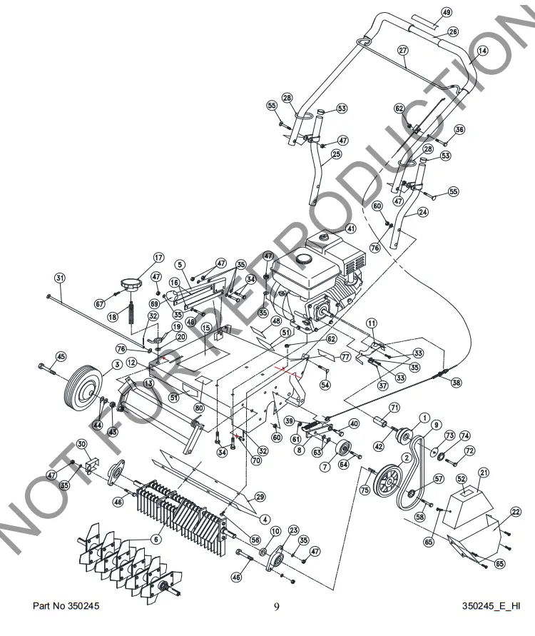
CR PARTS LIST
| item no. | PARTS LIST | CR550HC Part No. | QTY | CR550HCEU Part No. | QTY | CR550H Part No. | QTY | |||
| 1 | Pulley 3.0″ O.D. | 350101 | 1 | 350101 | 1 | 350101 | 1 | |||
| 2 | Pulley 5.5″ O.D. X ¾” | 350206 | 1 | 350206 | 1 | 350206 | 1 | |||
| 3 | Wheel 8″ Semi-Pneu White | 350236 | 4 | 350236 | 4 | 350236 | 4 | |||
| 4 | Bar Strap | 350211 | 1 | 350211 | 1 | 350211 | 1 | |||
| 5 | Rod Height Wa | 350220 | 1 | 350220 | 1 | 350220 | 1 | |||
| 6 | Reel Flail Assy (see page 10 & 11 for parts list and detailed dwg.) | 350241-S | 1 | 350241-S | 1 | 350241 | 1 | |||
| 7 | Pulley Idler 2.75″ | 350114 | 1 | 350114 | 1 | 350114 | 1 | |||
| 8 | Arm Idler WA | 350115 | 1 | 350115 | 1 | 350115 | 1 | |||
| 9 | Belt 5L X 34″ | 350207 | 1 | 350207 | 1 | 350207 | 1 | |||
| 10 | Spacer Reel Pulley | 350118 | 1 | 350118 | 1 | 350118 | 1 | |||
| 11 | Bracket Belt Finger | 350208 | 1 | 350208 | 1 | 350208 | 1 | |||
| 12 | Chassis WA W/ Label | 350235 | 1 | 350235 | 1 | 350235 | 1 | |||
| 13 | Frame Front WA | 350213 | 1 | 350213 | 1 | 350213 | 1 | |||
| 14 | GRIP 1″ x 13″ | 400570 | 2 | 400570 | 2 | 400570 | 2 | |||
| 15 | Label Instr. Hgt. Adj. | 350224 | 1 | 350224 | 1 | 350224 | 1 | |||
| 16 | Link Height Bar | 350223 | 2 | 350223 | 2 | 350223 | 2 | |||
| 17 | Knob Height Adj. | 850154 | 1 | 850154 | 1 | 850154 | 1 | |||
| 18 | STUD 3/4″-10 X 5 1/2″ PLTD | 810538 | 1 | 810538 | 1 | 810538 | 1 | |||
| 19 | LOCKNUT ASSY | 800227 | 1 | 800227 | 1 | 800227 | 1 | |||
| 20 | WASHER 3\4″ NYLON | 800109 | 1 | 800109 | 1 | 800109 | 1 | |||
| 21 | Guard Belt Top Wa | 350248 | 1 | 350248 | 1 | 350248 | 1 | |||
| 22 | Guard Belt Bottom Wa | 350249 | 1 | 350249 | 1 | 350249 | 1 | |||
| 23 | Bearing ¾” Cast Flange | 350209 | 2 | 350209 | 2 | 350209 | 2 | |||
| 24 | Handle Lower LH WA | 350134 | 1 | 350134 | 1 | 350134 | 1 | |||
| 25 | Handle Lower RH WA | 350135 | 1 | 350135 | 1 | 350135 | 1 | |||
| 26 | Handle Upper PR500 | 350136 | 1 | 350136 | 1 | 350136 | 1 | |||
| 27 | Bail Clutch WA | 350137 | 1 | 350137 | 1 | 350137 | 1 | |||
| 28 | Loop Folding Handle | 350138 | 2 | 350138 | 2 | 350138 | 2 | |||
| 29 | Deflector Rubber | 350210 | 1 | 350210 | 1 | 350210 | 1 | |||
| 30 | Guard Shaft CR | 350250 | 1 | 350250 | 1 | 350250 | 1 | |||
| 31 | PIN LIFT FRONT 3/8″ X 21 3/16″ Long | 350212 | 1 | 350212 | 1 | 350212 | 1 | |||
| 32 | PIN COTTER 1/8″ X 1″ Z/P | 900471 | 1 | 900471 | 1 | 900471 | 1 | |||
| 33 | SCREWCAP 5/16-24×3/4″ GR5 | 8042026 | 2 | 8042026 | 2 | 8042026 | 2 | |||
| 34 | SCREWCAP 5/16 – 18 x 1 1/2 | 8041030 | 6 | 8041030 | 6 | 8041030 | 6 | |||
| 35 | WASHER 1/4″ FLAT Z/P | 8171002 | 13 | 8171002 | 13 | 8171002 | 13 | |||
| 36 | SCREWCAP 1/4″-20X1.5″ | 8041008 | 1 | 8041008 | 1 | 8041008 | 1 | |||
| 37 | BELT FINGER WIRE | 350301 | 1 | 350301 | 1 | 350301 | 1 | |||
| 38 | Cable Clutch Reel PR500 | 350181 | 1 | 350181 | 1 | 350181 | 1 | |||
| 39 | Spring Extension | 350300 | 1 | 350300 | 1 | 350300 | 1 | |||
| 40 | Bolt Shoulder 1/2″ X 1″ | 500114 | 1 | 500114 | 1 | 500114 | 1 | |||
| 41 | ENGINE 5 HP HONDA GC160LAX QHG | 430700 | 1 | – | – | – | – | |||
| ENGINE 5.5 OHV HONDA GX160UT2 QX2 | – | – | – | – | 600115 | 1 | ||||
| ENGINE 5 HP HONDA GC160AQHL | – | – | 350426EU | 1 | – | – | ||||
| 42 | KEY 3/16″ X 1″ | 9201078 | 1 | 9201078 | 1 | 9201078 | 1 | |||
| 43 | NUT 1/2 – 13 JAM | 8162005 | 4 | 8162005 | 4 | 8162005 | 4 | |||
| 44 | WASHER 1/2 SAE | 8172011 | 8 | 8172011 | 8 | 8172011 | 8 | |||
| 45 | SCREWCAP 1/2-13 x 3″ Z/P | 8041102 | 4 | 8041102 | 4 | 8041102 | 4 | |||
| 46 | SCREWCAP 5/16″-18X1 1/4″ HCS ZP | 8041029 | 5 | 8041029 | 5 | 8041029 | 5 | |||
| 47 | NUT LOCK 5/16-18 | 8160002 | 13 | 8160002 | 13 | 8160002 | 13 | |||
| 48 | LABEL DANGER THROWN OBJECT | 810736 | 1 | 810736 | 1 | 810736 | 1 | |||
| 49 | LABEL CLUTCH VQ | 830503 | 1 | 830503 | 1 | 830503 | 1 | |||
| 51 | LABEL WARNING | 400424 | 2 | 400424 | 2 | 400424 | 2 | |||
| 52 | LABEL DANGER GUARD | 900327 | 1 | 900327 | 1 | 900327 | 1 | |||
| 53 | PLUG CAP 1″ RD | 890132 | 2 | 890132 | 2 | 890132 | 2 | |||
| 54 | BOLT CARRAIGE 3/8-16 x 1 3/4 | 8024061 | 4 | 8024061 | 4 | 8024061 | 4 | |||
| 55 | BOLT CARRAIGE 5/16-18 x 1 3/4 | 8024043 | 2 | 8024043 | 2 | 8024043 | 2 | |||
| 56 | SCREWCAP 1/4-20×1″ | 8041006 | 4 | 8041006 | 4 | 8041006 | 4 | |||
| 57 | LOCK WASHER TWISTED TOOTH | 400502 | 1 | 400502 | 1 | 430502 | 2 | |||
| 58 | SCREWCAP 3/8-16×1″ REEL ASSEMBLY | 8041050 | 1 | 8041050 | 1 | 8041050 | 1 | |||
| 60 | NUT LOCK 3/8-16 | 8160003 | 5 | 8160003 | 5 | 8160003 | 5 | |||
| 61 | NUT LOCK 3/8-16 THIN | 8161042 | 1 | 8161042 | 1 | 8161042 | 1 | |||
| 62 | NUT LOCK 1/4-20 | 8160001 | 5 | 8160001 | 5 | 8160001 | 5 | |||
| 63 | WASHER 5/16 FLAT CUT | 8171003 | 2 | 8171003 | 2 | 8171003 | 2 | |||
| 64 | SCREWCAP 3/8-16×1.5″ | 8041052 | 1 | 8041052 | 1 | 8041052 | 1 | |||
| 65 | SCREWCAP SHEET METAL DRILL POINT 1/4X3/4 | 430208 | 6 | 430208 | 6 | 430208 | 6 | |||
| 67 | SCREW MACH. #10-24X2″ | 8059143 | 1 | 8059143 | 1 | 8059143 | 1 | |||
| 69 | Knob Height Adj. | 430128 | 1 | 430128 | 1 | 430128 | 1 | |||
| 70 | WASHER 5/16 SAE | 8172009 | 1 | 8172009 | 1 | 8172009 | 1 | |||
| 71 | SPACER CRANK CR HONDA | 350338 | 1 | 350338 | 1 | 350338 | 1 | |||
| 72 | SCREWCAP 5/16-24 x 1 1/4″ GR. 8 | 400389 | 1 | 400389 | 1 | 400389 | 1 | |||
| 74 | WASHER TWISTED TOOTH | 400389 | 1 | 400389 | 1 | 400389 | 1 | |||
| 75 | KEY 3/16″ X 5/8″ | 9201072 | 1 | 9201072 | 1 | 9201072 | 1 | |||
| 76 | 3/8 FLAT CUT WASHER | 8171004 | 5 | 8171004 | 5 | 8171004 | 5 | |||
| 77 | LABEL SPARK ARRESTOR | 100256 | 1 | 100256 | 1 | 100252 | 1 | |||
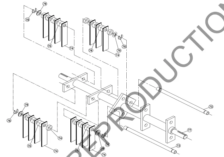
LAIL REEL ASSY 350241-S
| item no. | PARTS LIST | Part No. | QTY |
| 73 | SHAFT FLAIL BLADE | 350141 | 4 |
| 74 | BLADE FLAIL | 350205 | 30 |
| 76 | SPACER BUMPER 5/8″ x 1/2″ | 350144 | 54 |
| 77 | SHAFT WA FLAIL REEL | 350145 | 1 |
| 78 | CLIP LOCK 1/2″ | 350146 | 8 |
| 79 | WASHER 1/2 SAE | 8172011 | 8 |
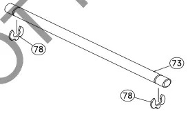
FLAIL SHAFT KIT 350185
 | |||
| item no. | PARTS LIST | Part No. | QTY |
| 73 | SHAFT FLAIL BLADE | 350141 | 4 |
| 78 | CLIP LOCK 1/2″ | 350146 | 8 |
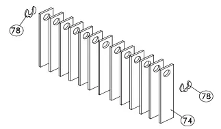
FLAIL BLADE KIT 350251 -S
 | |||
| item no. | PARTS LIST | Part No. | QTY |
| 74 | BLADE FLAIL | 350205 | 30 |
| 78 | CLIP LOCK 1/2″ | 350146 | 8 |
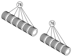
SPACER BUMPER KIT 350258
| item no. | PARTS | QTY | |
| LIST | Part No. | ||
| 76 | SPACER BUMPER 5/8″ x 1/2″ | 350144 | 54 |
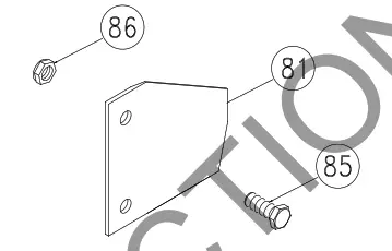
SLICING BLADE KIT 350187
 | |||
| item no. | PARTS LIST | PR500 Part No. | QTY |
| 81 | BLADE SLICING REEL | 350147 | 20 |
| 85 | SCREWCAP 1/4-20 X 3/4 HCS ZP | 8041004 | 40 |
| 86 | NUT LOCK 1/4-20 | 8142004 | 40 |
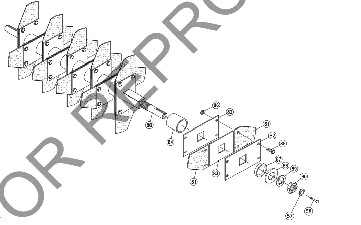
SLICING REEL ASSY 350252
| item | PARTS | PR500 | QTY |
| no. | LIST | Part No. | |
| 57 | WSHR-STL, BLV, .386″ X 1.063″ X .082″ MZ | 8181012 | 1 |
| 58 | SCREWCAP 3/8″-16 X 1″ HCS ZP | 8041050 | 1 |
| 80 | SHAFT SLICING WA | 350142 | 1 |
| 81 | BLADE SLICING REEL | 350147 | 20 |
| 82 | PLATE BLADE MTG. | 350253 | 20 |
| 83 | SPACER BLADE MTG. | 350254 | 10 |
| 84 | SPACER, REEL PM | 350443 | 9 |
| 85 | SCREWCAP 1/4-20 X 3/4 HCS ZP | 8041004 | 40 |
| 86 | NUT LOCK 1/4-20 | 8142004 | 40 |
| 87 | SPACER, HARDENED REEL OS900SP | 351297 | 1 |
| 88 | WASHER 0.937 x 1.750 x 0.119 | 350153 | 1 |
| 89 | WASHER LOCK 7/8 INT. TOOTH | 350154 | 1 |
| 90 | NUT JAM 7/8-14 | 350155 | 1 |
![]() COMPACT POWER RAKE Owner’s Manual
COMPACT POWER RAKE Owner’s Manual
CR550HC, CR550H, CR550HCEU
Beginning Serial #: 122020001


