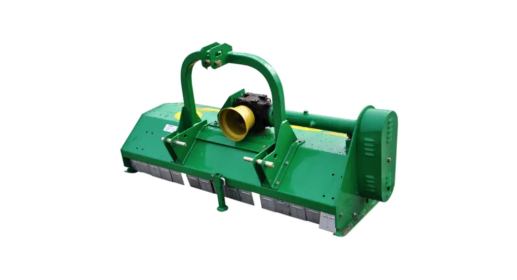
![]() FLAIL MOWER
FLAIL MOWER
BE-DP(S)XXX
 OPERATIONS & PARTS MANUAL
| PURCHASE DATE | MODEL NO. | SERIAL NUMBER |
| DEALER |
Safety at all times
Thoroughly read the instructions given in this manual before operation. Refer to the “Safety Decals” and read the instructions given in this manual before operation. Refer to the “Safety Decals” and read all instructions noted on them. Do not allow anyone to operate this equipment who has not fully read and comprehended this manual and who has not been properly trained in the safe operation of the equipment.
- Operator should be familiar with all functions of the unit.
- Operate implement from the driver’s seat only.
- Make sure all guards and shields are in place and secured before operating the implement.
- Do not leave the tractor or implement unattached with the engine running.
- Dismounting from a moving tractor could cause serious injury or death.
- Do not stand between tractors and the implement during hitching.
- Keep hands, feet, and clothing away from power-driven parts.
- Wear snug-fitting clothing to avoid entanglement with moving parts.
- Watch out for wires, trees, etc. when raising implement. Make sure all persons are clear of the working area.
- Turning the tractor too tight may cause the implement to ride up on wheels. This could result in injury or equipment damage.
Look For the Safety Alert Symbol!
The SAFETY ALERT SYMBOL indicates there is a potential hazard to personal safety and extra safety precautions must be taken. When you see this symbol, be alert and carefully read the message that follows it.
In addition to the design and configuration of equipment, hazard control, and accident prevention are dependent upon the awareness, concern, prudence, and proper training of personnel involved in the operation, transport, maintenance, and storage of equipment.
Be Aware of Signal Words!
A signal word designates a degree or level of hazard seriousness. The signal words are:
![]() DANGER!
DANGER!
Indicates an imminently hazardous situation that, if not avoided, will result in death or serious injury. This signal word is limited to the most extreme situations, typically for machine components that, for functional purposes, cannot be guarded.![]() WARNING!
WARNING!
Indicates a potentially hazardous situation that, if not avoided, could result in death or serious injury and includes hazards that are exposed when guards are removed. It may also be used to alert against unsafe practices.![]() CAUTION!
CAUTION!
Indicates a potentially hazardous situation which, if not avoided, may result in minor or moderate injury, it may result in minor or moderate injury. It may also be used to alert against unsafe practices.
For Your Protection
Thoroughly read the “Safety Label” section. Read all instructions as noted.
Shutdown and Storage
- Lower the machine to the ground put the tractor in park, turn o_ engine and remove the ignition key.
- Detach and store implements in an area away from children. Secure implementation with blocks and supports.
Use Safety Lights and Devices
- Slow moving tractors, self-propelled equipment, and towed implements can create a hazard when driven on public roads. They are difficult to see especially at night.
- Flashing warning lights and turn signals are recommended whenever driving on public roads. Use lights and devices provided with implement.
Transport Machinery Safely
- Comply with state and local laws.
- Maximum transport speed for implementation is 20 mph. Do not exceed. Never travel at a speed that does not allow adequate control of steering and stopping. Some rough terrain and a slower speed.
- Sudden braking can cause a towed load to swerve and upset. Reduce speed if a towed load is not equipped
with brakes. - Use the following maximum speed-tow load weight ratios as guidelines:
- 20 mph when weight is less than or equal to the weight of the tractor.
- 10 mph when weight is double the weight of the tractor.
IMPORTANT: Do not tow a load that is more than double the weight of the tractor.
Keep Riders Off Machinery
- Riders obstruct the operator’s view and could be struck by foreign objects or thrown from the machine.
- Never allow children to operate the equipment.
Practice Safe Maintenance
- Understand procedure first, Use proper tools and equipment. Refer to Operator’s Manual for additional information.
- Work in a clean dry area.
- Lower the implement to the ground, put the tractor in park, turn off the engine and remove the key before
performing maintenance.
- Allow the implement to cool completely
- Do not grease or oil implement while it is operating.
- Inspect all parts. Make sure parts are in good condition and installed properly.
- Remove buildup of grease, oil or debris.
- Remove all tools and unused parts from implementation before operation.
Prepare For Emergencies
- Be prepared if a fire starts.
- Keep a first aid kit and fire extinguisher handy.
- Keep emergency numbers for police, ambulance, and fire department near the phone.
Wear Protective Equipment
- Protective clothing and equipment should be worn.
- Wear clothing and equipment appropriate for the job. Avoid loose-fitting clothing.
- Prolonged exposure to loud noise can cause hearing impairment or hearing loss. Wear suitable hearing
- protection such as earmuffs or earplugs.
- Operating equipment safely requires the full attention of the operator. Avoid wearing headphones while operating machinery.
Avoid High Pressure Fluids Hazard
- Escaping fluid under pressure can penetrate the skin causing serious injury.
- Avoid the hazard by relieving pressure before disconnecting hydraulic lines.
- Use a piece of paper or cardboard, not body parts, to check for suspected leaks. Wear protective gloves and safety glasses or goggles when working with hydraulic systems.
- If an accident occurs, see seek medical attention immediately. Any fluid injected into the skin must be treated within a few hours or gangrene may result.
Safety Labels
Your Flail Mower comes equipped with all safety labels in place. They are designed to help you safely operate your implement. Read and follow their directions.
- Keep all safety labels clean and legible.
- Refer to this section for proper label placement.
To install new labels:
- Clean the area where the label is to be placed.
- Spray soapy water on the surface where the label is to be placed.
- Peel backing from label. Press firmly onto the surface.
- Squeeze out air bubbles with the edge of a credit card.

INTRODUCTION
Braber Equipment welcomes you to the growing family of new product owners. This implement has been designed with care and built by skilled workers using quality materials. Proper assembly, maintenance, and safe operating practices will help you get years of satisfactory use from the machine.
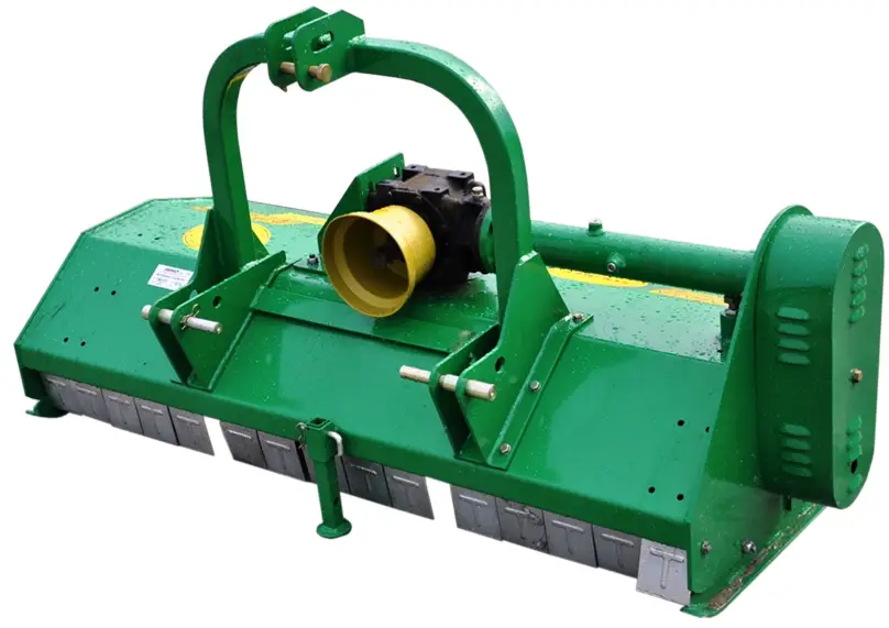
Application
The Flail Mowers are designed for category 1 3-PT Hitch or quick-hitch system mounting. These Fixed Bar Flail Mowers are ideal for ripping, leveling, finish grading, and backfilling applications at feedlots, outdoor arenas, building sites, and maintenance operations on farms and roadways.
Using This Manual
• This Operator’s Manual is designed to help familiarize you with safety, assembly, operation, adjustments, troubleshooting, and maintenance. Read this manual and follow the recommendations to help ensure safe and efficient operation.
• The information over time to assure you of the best performance.
Terminology
“Right” or “Left” as used in this manual is determined by facing the direction the machine will operate while in use unless otherwise stated.
Definitions
Note: A special point of information that the operator must be aware of before continuing.
Important: A special point of information related to its preceding topic. The intention is that this information should be read and noted before continuing.
Owner Assistance
The Warranty Registration card should be filled out by the dealer at the time of purchase. This information is necessary to provide you with quality customer service. If customer service or repair parts are required, contact a dealer. A dealer has trained personnel, repair, and equipment needed to service the machine. The parts on your machine have been specially designed and should only be replaced with genuine parts.
Serial Number Plate
For prompt service always use the serial number and model number when ordering parts from your dealer. Be sure to include your serial and model numbers in correspondence also.
ASSEMBLY & SET-UP
Tractor Requirements
This mower is designed with a 3-PT category! Hitch. The tractor’s horsepower rating should not exceed 80 PTO horsepower.
Assembly
Refer to the parts illustration.
Tractor Hook-Up
- Be certain that the tractor drawbar will not interfere. Move the drawbar ahead or remove it if required. Drawbar should also be checked for clearance when the unit is being raised for the first time.
- Align the lower link arms of the tractor to hitch clevises on the mower. Insert lower hitch pins into lower ball swivels and attach lynchpins.
- Attached tractor top link to the upper floating hitch on the mower with the pin supplied. Secure with lock pin.
- Adjust the tractor top link in or out to place the upper hitch pin vertically above or slightly behind the lower hitch pins to allow mower flotation. The mower should be run with the back 15 degrees lower than the front.
Driveline Installation
- Slide the driveline end with an extended safety cone over the splined shaft of the gearbox and secure it with attaching device.
- Slide the driveline over the tractor’s splined PTO shaft and secure it with a locking device.
- Driveline should now be moved back and forth to ensure that it is secure on the PTO shaft of the tractor and mower gearbox.
- Attach the chain from the driveline shield to one of the upper hitch braces to ensure that the shield does not rotate.
- Should the driveline require shortening:
• Hold half-shafts next to each other in the shortest working position and mark them.
• Shorten inner and outer guard tubes equally.
• Shorten inner and outer sliding profiles by the same length as the guard tubes.
• Proper overlap is a minimum of one-half the length of each tube, with both tubes being of equal length.
• Round off all sharp edges and remove burrs. Grease sliding profiles.
![]() CAUTION!
CAUTION!
Tractor PTO shield and all mower guards must be in place at all times during operation!
OPERATING INSTRUCTIONS
Transporting
Note: Always disengage PTO before raising the mower to the transport position.
- When raising the mower to the transport position, be sure that the driveline does not contact the tractor or mower. Adjust and set the tractor 3PT hitch lift height so that the driveline does not contact the mower deck in the fully raised position.
- Be sure to reduce tractor ground speed, when turning, leaving enough clearance so that the mower does not contact obstacles such as buildings, trees, or fences.
- Select a safe ground travel speed when transporting from one area to another. When traveling on roadways, transport in such a way that faster-moving vehicles may pass safely.
- When traveling over rough or hilly terrain, shift the tractor to a lower gear.
![]() CAUTION!
CAUTION!
When traveling on public roads, whether at night or during the day, use accessory lights and devices to adequately warn operators of other vehicles. Comply with all federal, state, and local laws.
Mowing Instructions
- Clear area to be mowed of objects and debris that might be picked up and thrown by the mower blades.
- Grass is best cut when it is dry. Mowing wet grass can cause plugging resulting in grass clumps behind the mower.
- Grass should be mowed frequently as shorter clippings deteriorate faster.
- If mowing extremely tall grass, it is best to raise cutting height and mow the area, then lower cutting height and mow a second time at the desired height.
Operating Instructions
Proper servicing and adjustments are the keys to the long life of any machine. With the careful and systematic inspection of the mower, costly maintenance, time and repair can be avoided. Before beginning to mow, the following inspection should be performed:
- Check the oil level in the gearbox.
- Check that all plugs in the gearbox have been replaced and tightened properly.
- Be sure all mower knives, bolts, and nuts are tight.
- Be certain all guards and shields are in place and secure.
- Grease the driveline shaft and all other grease fittings.
- Clear the area to be mowed of rocks, branches, and other foreign objects.
- Lower mower to ground. Set tractor throttle at approximately 1/4 open. Engage PTO to start blades rotating.
- Operate with 540 RPM PTO
- Begin mowing at a slow forward speed and shift up until the desired speed is achieved, maintaining 540 PTO RPM.
- Mower knives will cut better at a faster blade speed than at reduced throttle.
- After mowing the first 50 feet, stop and check to see that the mower is adjusted properly.
- Do not make sharp turns or attempt to back up while mower is on the ground.
- Do not engage PTO with mower in the fully raised position. Do not engage PTO at full throttle.
ADJUSTMENTS
Leveling the Mower
Note: Tractor and mower should be on level ground. Leveling can be adjusted at the tractor’s 3PT arms and center link.
Cutting Height Adjustment
The machine’s cutting height depends on the position of the rear roller.
- Remove the bolts that fix the roller on both sides.
- Lift lower both sides of rollers in equal measurements.
- Replace bolts and re-tighten them.
3PT Hitch Adjustments
The 3PT hitch system on this mower has been designed for front-to-back flotation when mowing on uneven terrain. Adjust the tractor’s top center link to place the upper hitch pin vertically above or slightly behind the lower hitch pins. The mower should be run with the back 15 degrees lower than the front. The hitch can also be adjusted from side to side by turning the adjustment handle. Turn the handle until you have achieved your desired location.![]() CAUTION!
CAUTION!
Engage parking brake, shut off tractor, remove key and disengage PTO before making any height adjustments!
Belt Tension![]() CAUTION!
CAUTION!
Belt drive system under spring tension; use care to avoid bodily harm!
The belt tension should be checked after the first 20 hours of use and then every 40 hours of use. 1. Tension on the belt can be adjusted with the belt tension bolt. Turn bolt until desired tension is achieved. When the belt has the correct tension, the gearbox should be adjusted so that the gearbox extension is running straight (parallel) with the flail mower. Loosen bolts at the bottom of the gearbox and move the gearbox until the gearbox extension is running straight.![]() CAUTION!
CAUTION!
Excessive tension on the belt may lead to premature failure of belt and drive components.
Excessive tension on the belt may also to safety hazard to the operator or bystanders.
MAINTENANCE & LUBRICATION
Proper servicing and adjustment are the keys to the long life of any farm implement. With careful and systematic inspection, you can avoid costly maintenance, time, and repair.
![]() CAUTION!
CAUTION!
For safety reasons, each maintenance operation must be performed with the tractor PTO disengaged, Mower lowered completely to the ground and the tractor engine shut off with the ignition key removed.
- After using the mower for several hours, check all bolts to be sure they are tight and check the drive belt tension.
- Replace any worn, damaged or illegible safety decals by obtaining new decals from dealer.
Knife Replacement
Important: Make sure that the knife is the same length as the others on the mower.
This will keep the rotor rotation balanced.
- Remove bolt and nut.
- Remove the old knife.
- Install new knife and existing bolt.
- Secure with nut.
![]() CAUTION!
CAUTION!
Belt drive system under spring tension; use care to avoid bodily harm!
- Remove belt guard fender and belt cover.
- Disengage belt tension by loosening belt tension bolt until belt can be removed.
- With tension relieved from the belt remove the old belt from pulleys.
- Tighten belt tension bolt.
- Re-install belt guard and belt guard fender.
Storage
At the end of the working season or when the mower will not be used for a long period, it is good practice to clean off any dirt or grease that may have accumulated on the mower and any moving parts.
- Clean as necessary.
- Check knives for wear and replace if necessary.
- Inspect the mower for loose, damaged or worn parts and adjust or replace them as needed.
- Store the unit inside, if possible, for longer life.
- Repaint parts where paint is worn or scratched to prevent rust.
- Replace all damaged or missing decals.
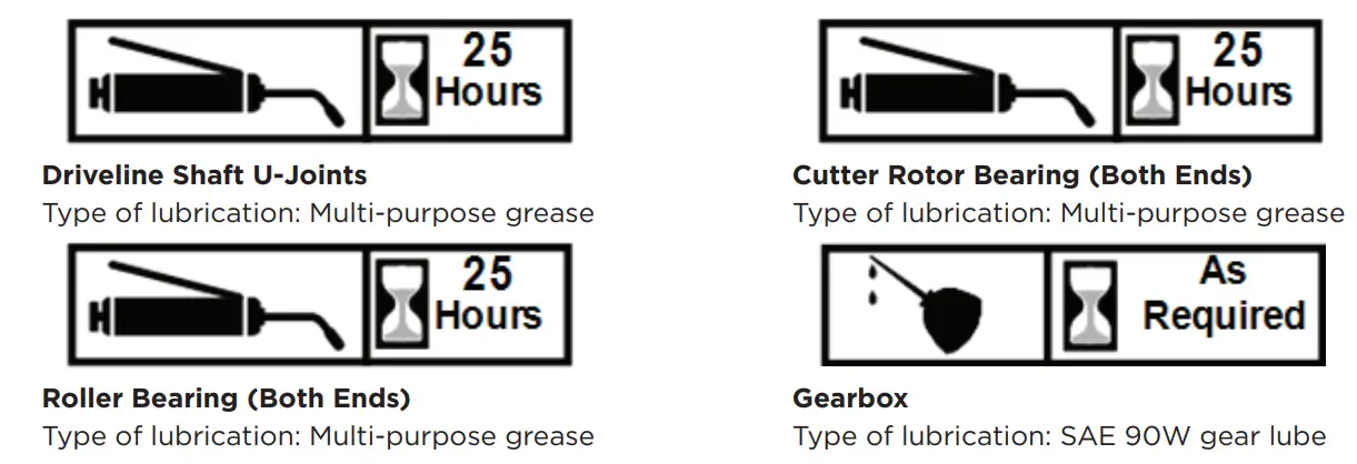
Check the oil level in the gearbox by removing the plug located on the right-hand side. Oil should be level with the bottom of the plug hole. Add oil if necessary by removing the top fill plug and side plug. Add oil until it flows from the side plug hole. DO NOT OVERFILL!
IMPORTANT: Mower should be level when checking the oil in the gearbox.

SPECIFICATIONS & CAPACITIES
| MODEL | DPS125 | DPS155 | DPS175 | DPS205 | DPS220 |
| Structure Weight | 300 kg | 330 kg | 360 kg | 308 kg | 410 kg |
| Working Width | 125 cm | 155 cm | 175 cm | 205 cm | 220 cm |
| Blade Type & Numbers | 20 hammers | 24 hammers | 28 hammers | 32 hammers | 32 hammers |
| Hitch Type | Standard 3PT Hitch | ||||
| Power Required | 40-80 hp | 40-80 hp | 40-80 hp | 60-80 hp | 60-100 hp |
| MODEL | DP155 | DP175 | DP205 | DP220 |
| Hydraulic Movement | 450 mm | 450 mm | 450 mm | 450 mm |
| Working Width | 380 kg | 410 kg | 430 kg | 460 kg |
| Working Width | 155 cm | 175 cm | 205 cm | 220 cm |
| Blade Type & Numbers | 24 hammers | 28 hammers | 32 hammers | 32 hammers |
| Hitch Type | Standard 3PT Hitch | |||
| Power Required | 40-80 hp | 40-80 hp | 60-80 hp | 60-100 hp |
![]() CAUTION!
CAUTION!
Do not try to clean rear discharge when the mower is running. Bodily harm may occur!
TROUBLESHOOTING
| PROBLEM | SOLUTION |
| Belt Slipping | Unplug and clean the mower deck. Remove belt guard shields and clean sheaves. Replace belt. |
| Patches Of Uncut Grass | Mow at full throttle (540 PTO RPM) Check PTO speed and tractor engine. Shift transmission to a lower gear. Tighten belts. Replace missing knives. |
|
Excessive Vibration | Replace knives. Replace drive belt. Replace drive belt. Replace pulleys or align. Remove belt guard shields & clean debris from belt area & sheaves. |
| Gearbox Noisy | Check lubricant level. |
| Knives Scalping Grass | Raise cutting height by adjusting the roller. Change mowing pattern. Reduce speed turns. |
| Uneven Cut | Shift to a lower gear. Level Mower. Replace missing knives. |
| Tractor Loaded Down By Mower | Mow at full throttle (540 PTO RPM). Shift to a lower gear. Clean mower. |
APPENDIX
Bolt Torque
The tables shown below give correct torque values for various bolts and cap screws. Tighten all bolts to the torques specified unless otherwise noted. Check the tightness of olts periodically, using the bolt torque chart as a guide. Replace hardware with the same strength bolt.
English Torque Specification
| BOLT SAE 2 SAE 5 SAE 8 DIAMETER N.M LB-FT N.M LB-FT N.M LB-FT | ||||||
| 1/4” | 8 | 6 | 12 | 9 | 17 | 12 |
| 5/16” | 13 | 10 | 25 | 19 | 36 | 27 |
| 3/8” | 27 | 20 | 45 | 33 | 63 | 45 |
| 7/16” | 41 | 30 | 72 | 53 | 100 | 75 |
| 1/2” | 61 | 45 | 110 | 80 | 155 | 115 |
| 9/16” | 95 | 60 | 155 | 115 | 200 | 165 |
| 5/8” | 128 | 95 | 215 | 160 | 305 | 220 |
| 3/4” | 225 | 165 | 390 | 290 | 540 | 400 |
| 7/8” | 230 | 170 | 570 | 420 | 880 | 650 |
Metric Torque Specifications
| BOLT DIAMETER | 8.8 N.M LB-FT | 10.9 N.M LB-FT | ||
| M3 | 0.5 | 0.4 | 1.8 | 1.3 |
| M4 | 3 | 2.2 | 4.5 | 3.3 |
| M5 | 6 | 4 | 9 | 7 |
| M6 | 10 | 7 | 15 | 11 |
| M8 | 25 | 18 | 35 | 26 |
| M10 | 50 | 37 | 70 | 52 |
| M12 | 90 | 66 | 125 | 92 |
| M14 | 140 | 103 | 200 | 148 |
| M16 | 225 | 166 | 310 | 229 |
| M20 | 435 | 321 | 610 | 450 |
| M24 | 750 | 553 | 1050 | 744 |
| M30 | 1495 | 1103 | 2100 | 1550 |
| M36 | 2600 | 1917 | 3675 | 2710 |
Torque figures indicated above are valid for non-greased or non-oiled threads and heads otherwise specified. Therefore, do not grease or oil bolts or cap screws unless otherwise specified in this manual. When using locking elements, increase torque value by 5%.
EXPLODED VIEW & PARTS LISTS
DPS FLAIL MOWER ASSEMBLY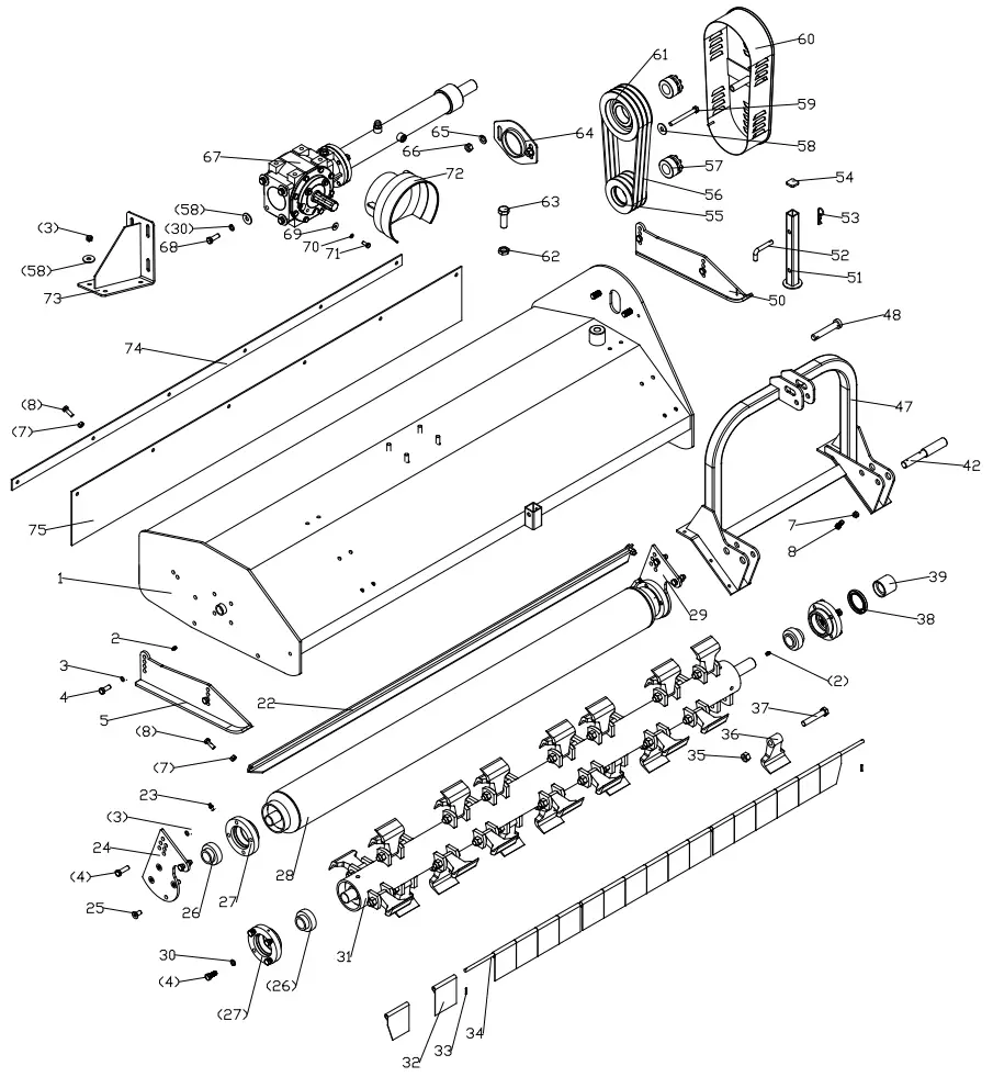
DPS FLAIL MOWER ASSEMBLY
| REF | PART NUM | DESCRIPTION | QTY |
| 1 | DPS175.013 | The cover weldment | 1 |
| 2 | GB1152-89/M8X1 | Oil cup M8X1 | 2 |
| 3 | GB6184-86/M12 | Locking nut M12 | 8 |
| 4 | GB5783-86/ M12X30 | Bolt M12x30 | 16 |
| 5 | DP175.015 | Base plate (R) | 1 |
| 7 | GB6184-86/M10 | Locking nut M10 (DPS 155) | 20 |
| (DPS175) | 20 | ||
| (DPS205) | 21 | ||
| 8 | GB5783-86/ M10X30 | Bolt M10x30 (DPS 155) | 20 |
| (DPS175) | 20 | ||
| (DPS205) | 21 | ||
| 22 | DP175.102 | Mud shield | 1 |
| 23 | JB/T7940.2-95/ M6 | Oil cup M6 | 2 |
| 24 | DP175.018 | Supporting for roller (L) | 1 |
| 25 | GB70.3-2000/ M12X25 | Hex. head bolt M12X25 | 8 |
| 26 | UC207-Z | Flange UC207-Z | 4 |
| 27 | EFGC125.115 | Bearing | 4 |
| 28 | DP175.020 | Roller weldment | 1 |
| 29 | DP175.019 | Supporting for roller (R) | 1 |
| 30 | GB93-87/12 | Spring washer 12 | 12 |
| 31 | EFGC125.018 | Blade axle weldment | 1 |
| 32 | EFGC125.113 | Fender (DPS 155) | 16 |
| (DPS175) | 18 | ||
| (DPS205) | 21 | ||
| 33 | GB879-86/4X22 | Elastic cylindrical pin 4×22 | 2 |
| 34 | EFGC125.104 | Shaft for fender | 1 |
| 35 | GB6184-86/ M16X1.5 | Locking nut M16X1.5 (DPS 155) | 24 |
| (DPS175) | 28 | ||
| (DPS205) | 32 | ||
| 36 | EFGC125.122A | Blade (DPS 155) | 24 |
| (DPS175) | 28 | ||
| (DPS205) | 32 | ||
| 37 | GB5785-2000 | Bolt M16X1.5X90 (DPS 155) | 24 |
| (DPS175) | 28 | ||
| (DPS205) | 32 |
| REF | PART NUM | DESCRIPTION | QTY |
| 38 | GB13871- 94/55X80X8 | Oil seal FB55X80X8 | 1 |
| 39 | EFGC125.116 | Oil-sealing sleeve | 1 |
| 42 | BM30.102 | Pin for lifting | 2 |
| 47 | DPS175.011 | Hanging weldment | 1 |
| 48 | EFGC125.123 | Pin shaft | 1 |
| 50 | DP175.014 | Base plate (L) | 1 |
| 51 | DP175.107 | Supporting frame | 1 |
| 52 | 1G135.00.107 | Bent pin | 1 |
| 53 | EFGC125.110 | R pin | 1 |
| 54 | EFGC125.112 | Cover | 1 |
| 55 | EFGC125.117A | Small belt pulley | 1 |
| 56 | GB/T1154-97/ SPB991 | Strap SPB991 | 4 |
| 57 | JB/ T7934Z3/35X60 | Swellable sleeve | 2 |
| 58 | GB96-85/12 | Plain washer 12 | 5 |
| 59 | GB5782-86/ M12X120 | Bolt M12X130 | 1 |
| 60 | EFGC125.012 | Belt cover | 1 |
| 61 | EFGC125.121A | Big belt pulley | 1 |
| 62 | GB6173-86/ M20x1.5 | Nut M20x1.5 | 1 |
| 63 | GB5786-86/ M20X1.5X55 | Bolt M20X1.5X55 | 1 |
| 64 | EFGC125.120 | Tension plate | 1 |
| 65 | GB97.1-85/14 | Plain washer 14 | 2 |
| 66 | GB6184-86/M14 | Locking nut M14 | 2 |
| 67 | DP175.022 | Gearbox assembly | 1 |
| 68 | GB5783-86/ M12X35 | Bolt M12x35 | 4 |
| 69 | GB96-85/8 | Plain washer 8 | 4 |
| 70 | GB93-87/8 | Spring washer 8 | 4 |
| 71 | GB5783-86/ M8X20 | Bolt M8x20 | 4 |
| 72 | DP175.104 | Guard shade | 1 |
| 73 | EFGC125.024 | Gearbox support | 1 |
| 74 | DP175.106 | Press plate | 1 |
| 75 | DP175.105 | Rubber plate | 1 |
DP FLAIL MOWER PARTS LIST
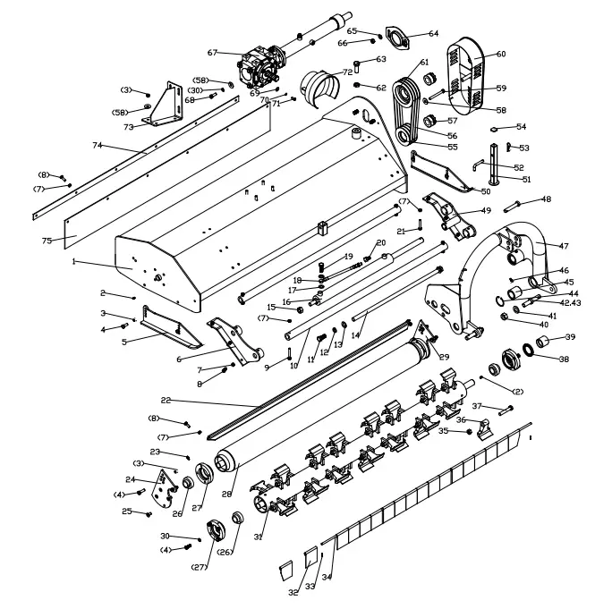
DP FLAIL MOWER PARTS LIST
| REF | PART NUM | DESCRIPTION | QTY |
| 1 | DP175.013 | The cover weldment | 1 |
| 2 | GB1152-89/M8X1 | Oil cup M8X1 | 2 |
| 3 | GB6184-86/M12 | Locking nut M12 | 12 |
| 4 | GB5783-86/M12X30 | Bolt M12x30 | 16 |
| 5 | DP175.015 | Base plate (R) | 1 |
| 6 | DP175.021 | Connecting bracket(L) | 1 |
| 7 | GB6184-86/M10 | Locking nut M10 (DP155) | 25 |
| (DP175) | 25 | ||
| (DP205) | 26 | ||
| 8 | GB5783-86/M10X30 | Bolt M10x30 (DP155) | 20 |
| (DP175) | 20 | ||
| (DP205) | 21 | ||
| 9 | GB5782-86/M10X70 | Bolt M10x70 | 4 |
| 10 | DP175.103 | Guide rail | 2 |
| 11 | GB5783-86/M18X40 | Bolt M18x40 | 2 |
| 12 | GB93-87/18 | Spring washer 18 | 2 |
| 13 | GB97.1-85/18 | Plain washer 18 | 2 |
| 14 | DP175.101 | Supporting tube | 2 |
| 15 | GB6184-86/M20 | Locking nut M20 | 1 |
| 16 | DP175.016 | Slippage cylinder | 1 |
| 17 | GB3451-86/16 | Washer 16 | 4 |
| 18 | DP175.017 | Oil pipe | 2 |
| 19 | GB3451/M16X1. 5X30 | Bolt M16X1.5X30 | 2 |
| 20 | EFGCH125.013 | Quick connector R1/2″ | 2 |
| 21 | GB5782-86/M10X60 | Bolt M10x60 | 1 |
| 22 | DP175.102 | Mud shield | 1 |
| 23 | JB/T7940.2-95/M6 | Oil cup M6 | 2 |
| 24 | DP175.018 | Supporting for roller (L) | 1 |
| 25 | GB70.3-2000/M12X25 | Hex. head bolt M12X25 | 8 |
| 26 | UC207-Z | Flange UC207-Z | 4 |
| 27 | EFGC125.115 | Bearing | 4 |
| 28 | DP175.020 | Roller weldment | 1 |
| 29 | DP175.019 | Supporting for roller (R) | 1 |
| 30 | GB93-87/12 | Spring washer 12 | 12 |
| 31 | EFGC125.018 | Blade axle weldment | 1 |
| 32 | EFGC125.113 | Fender (DP155) | 16 |
| (DP175) | 18 | ||
| (DP205) | 21 | ||
| 33 | GB879-86/4X22 | Elastic cylindrical pin 4×22 | 2 |
| 34 | EFGC125.104 | Shaft for fender | 1 |
| 35 | GB6184-86/M16X1.5 | Locking nut M16X1.5 (DP155) | 24 |
| (DP175) | 28 | ||
| (DP205) | 32 | ||
| 36 | EFGC125.122A | Blade (DP155) | 24 |
| (DP175) | 28 | ||
| (DP205) | 32 |
| REF | PART NUM | DESCRIPTION | QTY |
| 37 | GB5785-2000/M16X1.5X90 | Bolt M16X1.5X90 (DP155) | 24 |
| (DP175) | 28 | ||
| (DP205) | 32 | ||
| 38 | GB13871-94/55X80X8 | Oil seal FB55X80X8 | 1 |
| 39 | EFGC125.116 | Oil-sealing sleeve | 1 |
| 40 | GB6184-86/M22X1.5 | Locking nut M22X1.5 | 2 |
| 41 | GB97.1-85/22 | Plain washer 22 | 2 |
| 42 | EFGCH125.103 | Pin for lifting | 2 |
| 43 | EFGCH125.102 | Lockpin | 2 |
| 44 | GB893.1-86/60 | Circlip 60 | 4 |
| 45 | EFGCH125.107 | Nylon bush | 4 |
| 46 | GB1152-89/M6 | Oil cup M6 | 4 |
| 47 | DP175.011 | Hanging weldment | 1 |
| 48 | EFGC125.123 | Pin shaft | 1 |
| 49 | DP175.012 | Connecting bracket(R) | 1 |
| 50 | DP175.014 | Base plate (L) | 1 |
| 51 | DP175.107 | Supporting frame | 1 |
| 52 | 1G135.00.107 | Bent pin | 1 |
| 53 | EFGC125.110 | R pin | 1 |
| 54 | EFGC125.112 | Cover | 1 |
| 55 | EFGC125.117A | Small belt pulley | 1 |
| 56 | GB/T1154-97/SPB991 | Strap SPB991 | 4 |
| 57 | JB/T7934Z3/35X60 | Swellable sleeve | 2 |
| 58 | GB96-85/12 | Plain washer 12 | 9 |
| 59 | GB5782-86/M12X120 | Bolt M12X130 | 1 |
| 60 | EFGC125.012 | Belt cover | 1 |
| 61 | EFGC125.121A | Big belt pulley | 1 |
| 62 | GB6173-86/M20x1.5 | Nut M20x1.5 | 1 |
| 63 | GB5786-86/M20X1.5X55 | Bolt M20X1.5X55 | 1 |
| 64 | EFGC125.120 | Tension plate | 1 |
| 65 | GB97.1-85/14 | Plain washer 14 | 2 |
| 66 | GB6184-86/M14 | Locking nut M14 | 2 |
| 67 | DP175.022 | Gearbox assembly | 1 |
| 68 | GB5783-86/M12X35 | Bolt M12x35 | 4 |
| 69 | GB96-85/8 | Plain washer 8 | 4 |
| 70 | GB93-87/8 | Spring washer 8 | 4 |
| 71 | GB5783-86/M8X20 | Bolt M8x20 | 4 |
| 72 | DP175.104 | Guard shade | 1 |
| 73 | EFGC125.024 | Gearbox support | 1 |
| 74 | DP175.106 | Press plate | 1 |
| 75 | DP175.105 | Rubber plate | 1 |
DP(DPS) FLAIL MOWER GEARBOX ASSEMBLY
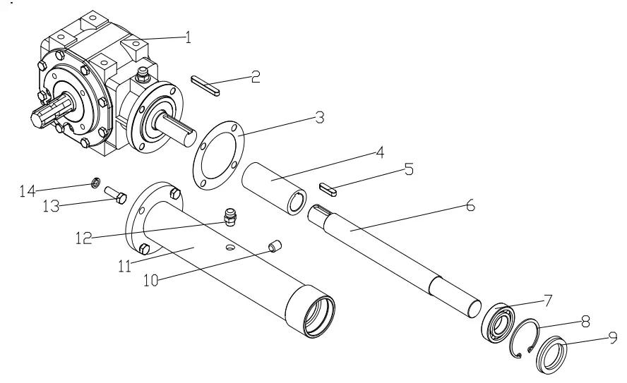
| REF | PART NUM | DESCRIPTION | QTY |
| 1 | TS50.300Z.02 | Gearbox assembly | 1 |
| 2 | GB1096-79/A10X70 | Key A10X70 | 1 |
| 3 | EFGC125.166 | Paper gasket | 1 |
| 4 | EFGC125.167 | Connected sleeve | 1 |
| 5 | GB1096-79/A10X40 | Key A10X40 | 1 |
| 6 | DP175.155 | Shaft | 1 |
| 7 | GB/T276-94/6207 | Bearing 6207 | 1 |
| 8 | GB893.1-86/72 | Circlip 72 | 1 |
| 9 | GB13871-94/35X72X10 | Oil seal 35×72×10 | 1 |
| 10 | ZBT 32001.3-87 | Retainer | 1 |
| 11 | DP175.023 | Shaft tube weldment | 1 |
| 12 | EFGC125.169 | Bolt of plug screw ZG3/8″-19 | 1 |
| 13 | GB5783-86/M12X35 | Bolt M12X35 | 4 |
| 14 | GB93-87/12 | Spring washer 12 | 12 |
DP (DPS) FLAIL MOWER GEARBOX LIST
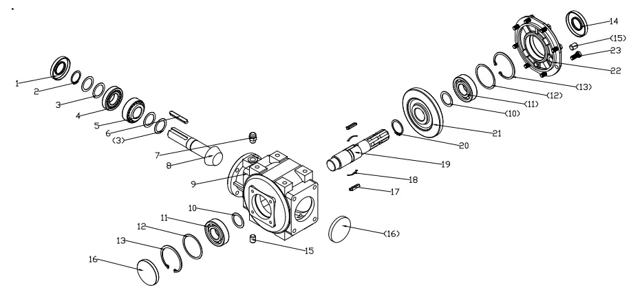
| REF | PART NUM | DESCRIPTION | QTY |
| 1 | GB9877.1-88/35X72X10 | Oil seal 35×72×10 | 1 |
| 2 | GB894.1-89/35 | Circlips for shaft 35 | 1 |
| 3 | TS50.300Z.01.110 | Washer (S) 0.7 | 4 |
| 4 | GB297-94/30207 | Bearing 30207 | 1 |
| 5 | GB297-94/32207 | Bearing 32207 | 1 |
| 6 | GB1096-79/10X65 | Key 10X65 | 1 |
| 7 | EFGC125.169 | Bolt of plug screw ZG3/8″-19 | 1 |
| 8 | TS50.300Z.01.111 | Bevel gear shaft | 1 |
| 9 | TS50.300Z.01.101 | Gearbox complete | 1 |
| 10 | TS50.300Z.01.105 | Washer (S) 1 | 2 |
| 11 | GB/T276-94/6307 | Bearing 6307 | 2 |
| 12 | TS50.300Z.01.104 | Washer (B) 0.7 | 2 |
| 13 | GB893.1-86/80 | Circlips for hole 80 | 2 |
| 14 | GB9877.1-88/35X80X10 | Oil seal 35×80×10 | 1 |
| 15 | ZBT 32001.3-87 | Retainer | 1 |
| 16 | TS50.300Z.01.106 | Seal cover | 2 |
| 17 | TS50.300Z.01.108 | Key | 2 |
| 18 | TS50.300Z.01.109 | Spring | 2 |
| 19 | TS50.300Z.02.103 | Pinion shaft | 1 |
| 20 | GB894.1-89/42 | Circlips for shaft 42 | 1 |
| 21 | TS50.300Z.01.107 | Bevel gear | 1 |
| 22 | TS50.300Z.01.102 | Gearbox cover | 1 |
| 23 | GB5783-86/M10X25 | Bolt M18x40 | 8 |
![]() BRABEREQ.COM
BRABEREQ.COM
[email protected]
PHONE: 604-850-7770
FAX: 604-850-7774
TOLL FREE PHONE: 1-877-588-3311
TOLL FREE FAX: 1-800-665-7334
BE-DP(S)XXX USER MANUAL


