
BRABER EQUIPMENT BE-AGMZ200 Flail Mower

INTRODUCTION
The AG Flails are primarily designed to mow grass, weeds and light brush. The mowers are assembled for operation with 1000 RPM tractor input only (rated PTO up to 45 HP) and supplied standard with Cat 1 lift pins for tractor attachment. The mowers can fit Cat 1 quick attach hitch, by using suitable bushing to adapt diameters of lift pins.
SYMBOLS
This booklet contains three “safety graphic symbols” which highlight the relevant danger levels or important information:
![]() DANGER!
DANGER!
It draws the operator’s attention to situations which can jeopardize people’s safety.![]() CAUTION!
CAUTION!
It draws the operator’s attention to situations which can jeopardizes the machine efficiency but not people’s safety.![]() IMPORTANT!
IMPORTANT!
It highlights general information which does not endanger people’s safety or the efficiency of the parts.
SAFETY LABELS
The safety labels and the information on the machine, listed in the following table, must be necessarily read and respected; failure to follow these warnings can cause death or sever injuries. Make sure that the labels are always present and legible, should this not be the case, contact your nearest dealer to replace the missing or illegible ones.
 | 1 – WARNING The operations of regulations and maintenance must be carried out after having read the use and maintenance handbook, with the machine still and the disengaged ignition key. |
 | 2. WARNING Danger of fluids under pressure. Read the handbook before to intervene and in case of injury address to a doctor. |
 | 3. WARNING Make sure of the rotation direction and of the number of revolutions (540 rev/min.) of the power taking of the tractor before to insert the PTO shaft. |
 | 4. WARNING – DANGER Make sure that the shredder is completely still before approaching it. |
 | 5. WARNING – DANGER of shearing of the feet. Keep away. |
 | 6. WARNING Possible throw of material and/or objects, do not stand, get through or approach the machine. |
 | Keep a minimum safety distance of 70 m from the machine. |
 | 7. WARNING It is forbidden to go on the machine when it is in movement. |
 | 8. WARNING Danger of catching and dragging. Do not approach the hands to the transmission shaft in motion. |
 | 9. WARNING Do not stand between the tractor and the machine. |
 | 10. DANGER of crash for the legs. Keep proper distance. |
 | 11. DANGER of squashing / shearing of the hands. |
 | 12. WARNING Hot surface. Keep the proper distance. |
 | 13. WARNING Do not remove or open the protection carters until the belts are completely still. |
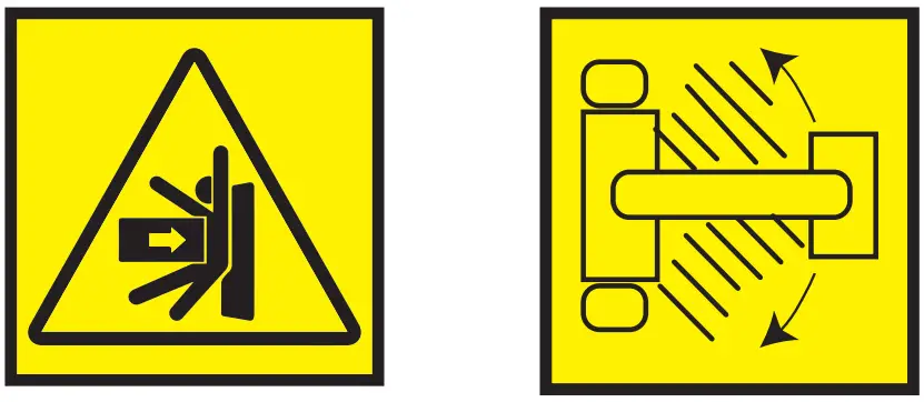 | 14. WARNING Danger of squashing. Do not stand in the move and side shifting zone of the machine. |
 | 15. WARNING For the lifting, hook the machine exclusively in the indicated points. |
16. Use the requested individual Protection Devices.
17. Greasing points.

SAFETY
Allowed Use:
Ag flail mowers, as described in this instruction and maintenance booklet, have been specifically designed to mow grass, weeds and light brush up to 1″ diameter. Any other use jeopardizes the operator’s safety and the machine’s integrity.
Improper Use:
The mower was designed to mow grass, weeds and light brush only. Only operate this mower on properly sized and equipped tractor. When using AG flail mowers, it is particularly forbidden:
- The attachment to tractors other than 1000 RPM PTO speed.
- To use other than 1000 RPM PTO speed.
- To work in excessively stony grounds.
- To work on excessive slopes.
- To approach the machine when wearing inappropriate work clothing.
- To get on the machine while it is being used or transported.
![]() DANGER!
DANGER!
Operating this mower in an application for which it is not designed and/or operating with the wrong size tractor can cause mower component damage and equipment failure resulting in possible serious injury or death.
SAFETY IN THE WORKPLACE:
Most of the accidents which take place while the operator is using the machine or the equipment or during their maintenance or repair are caused by a lack of compliance with basic safety precautions. If it is necessary, therefore, to become more and more conscious of the potential risks of one’s action by constantly paying attention to its effects. If potentially dangerous situations are known, accidents can be prevented!
OPERATOR’S REQUIREMENTS:
Physical: Good eyesight, coordination and capability of carrying out all functions required for the machine’s use.
Mental: Capability of understanding and applying the established rules and safety precautions. Users must pay attention and be sensible for their own and other people’s safety.
Training: User must have read and studied this manual, it’s eventual enclosed graphs and schemes and its identification and danger plates. They must be skilled and trained on any use or maintenance activities.
WORK CLOTHING:
When working and especially when executing repair or maintenance activities, it is necessary to wear the following clothing and safety accessories:
- Overalls or other comfortable clothing, not too loose to prevent th possibility that parts of them might get
caught in the moving parts. - Protective gloves for hands.
- Protective glasses or faceplate to protect eyes and face.
- Protective helmet for the head.
- Safety shoes


![]() IMPORTANT!
IMPORTANT!
Wear only personal safety accessories in good condition and complying with the rules in force.
GENERAL SAFETY RULES
Always consider the features of the area where work is taking place:
- When the equipment is running, it is forbidden to stand within the field of action of the shredder or of the other accessories of which it is provided with.
PREPARE THE WORK:
- Before and when working do not drink alcohol, take drugs, or any other substances which may alter your capability of working with machine tools.
- Be sure to have sufficient fuel, to prevent a forced stopping of the machine, maybe during a critical movement.
- Do not use equipment under unsafe conditions. For instance, it is forbidden to execute make shift repair activities just to start working; it is forbidden to work at night with an insufficiently illuminated working area.
- NEVER operate implement without all shields in place and in good operational condition. The operator must be familiar with the mower and tractor and all associated safety practices before operating the mower and tractor.
GENERAL SAFETY
When working or during the maintenance activities it is necessary to remember:
- The labels and stickers providing instructions and pointing out the dangers, must not be removed, hidden or made illegible.
- Do not remove, except in case of maintenance, the shields, guards and deflectors equipped on the mower. When it is necessary to remove them, restarting the engine and using the equipment. The mower is equipped with protective deflectors to prevent objects being thrown from the mower by the blades, however, no shielding is 100% effective. All shields guards and deflectors equipped on the mower must be maintained in good operational condition.
- It is forbidden to lubricate, clean and adjust the moving parts while they are running.
- During maintenance or adjustment activities on the equipment it is forbidden to use hands for executing operations for which there are specific tools.
- Do not use tools in bad condition or inappropriately, for instance pliers rather than monkey spanners, etc.
- When maintenance or repairs are completed that no tools, wiping rags or other materials are left inside spaces or guides with moving parts.
- While using the equipment, it is forbidden to make more than one person give directions and make signals. The eventual directions and signals relating to the load handling must be given by one person only.
- Do not unexpectedly call an operator while he is working if not necessary; it is forbidden as well to frighten or throw objects at the operator, even if just for fun.
- Watch out for those who are present, especially the children! · Do not make people get on the machine. · When the equipment is not needed, stop the vehicle’s engine, park it on flat ground with first speed and parking brake on, with the machine rested on the ground and PTO disengaged.
- Do not clean, lubricate, repair or adjust with the engine running and the machine lifted.
- Never use the machine on steep slopes which may jeopardize the equipment’s stability. The manufacturer declines all responsibility for lack of compliance with these instructions.
ASSEMBLY
ATTACHMENT TO THE TRACTOR:
Before operating the mower, carefully read this Operator’s Manual, completely understand the safety instructions and know how to operate correctly both the tractor and the PTO shaft, reading carefully the instruction manuals of the tractor and PTO shaft manufacturers. All AG Flail Mowers have been manufactured to be attached to any tractor provided with hydraulic and universal 3-Point hitch.
The tractor used to operate the mower must have the power, capacity and required equipment to safely operate the mower. Operating the mower on improperly sized and equipped tractors may cause tractor and/ or mower damage and could be a potential danger to the operator and passers-by. Before attaching the equipment to the tractor, set both on flat and smooth ground and make sure that nobody is standing between them.
Slowly move the tractor towards the flail mower by aligning the tractor hydraulic lift arms to the two mower hitches’ lateral brackets; stop engine and set parking brake. First connect the lower arms by removing the release pins of the brackets placed on the plates, inserting the lift arms into the arms center and fastening them with the relevant release pins, which had been removed. Then connect the tractor top link to the third upper point by removing the pin located between the plates, inserting the top link itself and locking it with the pin.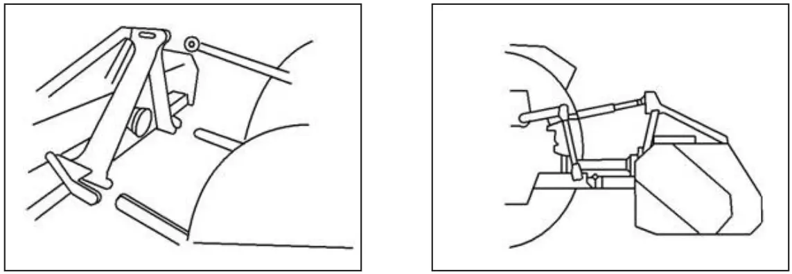
Adjust the third point so that the upper part of the frame is parallel to the ground. Lock all connections parts with the special sway chains or tie rods. It is always good to make sure that the central gearbox axis is parallel to the ground thus reducing the stresses on the power take-off and extending the working life of the equipment.
![]() DANGER!
DANGER!
Pay attention to the tractor’s front wheel grip when the equipment is set up and lifted; if the wheels appear to be too lightened, ballast the tractor front tires or add front weights.![]() CAUTION!
CAUTION!
After executing the above-mentioned activities, it is always good to check that all bolts and nuts of your shredder are tightened strongly (refer to the torque specifications in this manual).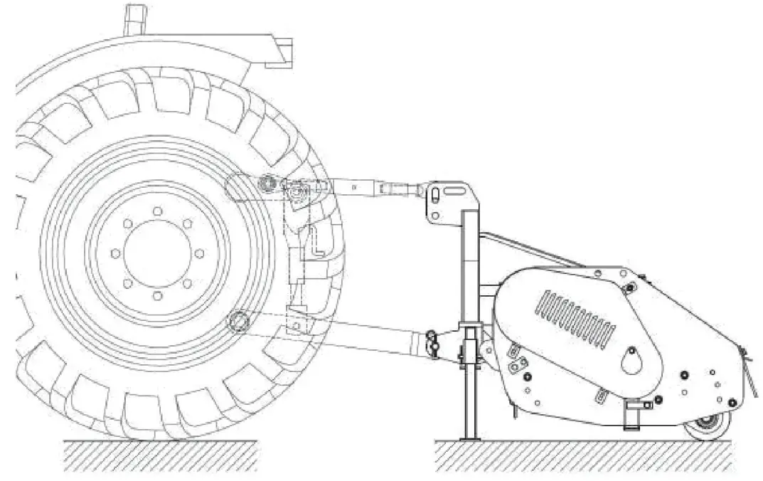
DRIVELINE ATTACHMENT
Before assembling the PTO shaft, check that its RPM and direction of rotation match those of the tractor. Moreover, read carefully the instruction manuals of the PTO shaft and the tractor manufacturers. Before starting work, make sure all safety shields are in place. Check in particular that the safety guards cover the PTO shaft throughout its extension. When attaching the mower input driveline to the tractor PTO, be sure that the connecting yoke spring activated locking collar slides freely and the locking balls are seated securely in the groove on the tractor PTO shaft. A driveline not attached correctly to the tractor PTO shaft could come loose and result in personal injury and damage to the implement.![]() CAUTION!
CAUTION!
Make sure the driveline will not bottom out (at its most compressed position there must be at least 3/4″ clearance between each profile end and opposite profile universal joint) or become disengaged (at its farthest extended position a minimum profile engagement of 1/3 of the length must be maintained).
Check out that the cardan shaft minimum and maximum length are the ones required by the machine-tractor coupling. Should problems arise, contact a skilled repair shop or the drive shaft retailer. After installation, secure safety guards both to the tractor and the machine using the special chains and make sure that they pivot freely. If the PTO shaft is equipped with other safety devices, such as a pair limiter or freewheels, be sure to install them on the machine side. As for the PTO use and maintenance, refer to the relevant booklet.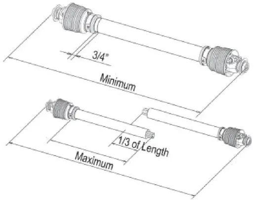
WORKING HEIGHT ADJUSTMENT
The machine’s working height is determined by the position of the rear roller. Lifting the roller, the cutters get close to the soil, whereas lowering it, the cutters get further from it. After a modification of the working height be sure that the cutters skim the ground; a direct contact with it would cause their wear and this could affect the cutting rotor balance and may cause objects to be thrown out from under the mower deck.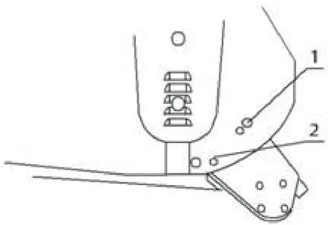
FLAIL MOWER ADJUSTMENT
- On a flat piece of ground, attach the flail mower to the tractor using the three point linkage.
- Use a solid adjustable top link.
- Lower the three point linkage to its lowest position.
- With the roller at the rear in contact with the ground, adjust the length of the top link so that the lower edge at the side of the flail mower is parallel with the ground.
- Rotate the blade drum by hand so that a row of blades hangs vertically towards the ground.
- Measure the clearance between the bottom of the extended blades and the ground.
- Minimum 50mm
- Note in rough or lumpy paddocks the clearance needs to be increased to ensure that blades don’t impact the ground.
- Adjust the roller height to increase or decrease the blade clearance as required.
- Go through steps 4 to 7 until the required clearance is achieved. When flail mower has been set up with the required tolerances, operate the flail mower with tractor in low range and the PTO delivering 1000 RPM.
DRIVE BELT ADJUSTMENT
Loosen the Screw A and B that locks the support shaft and loosen the counter nut C.
Loosen the screws that lock the gear box on the mounting plate D.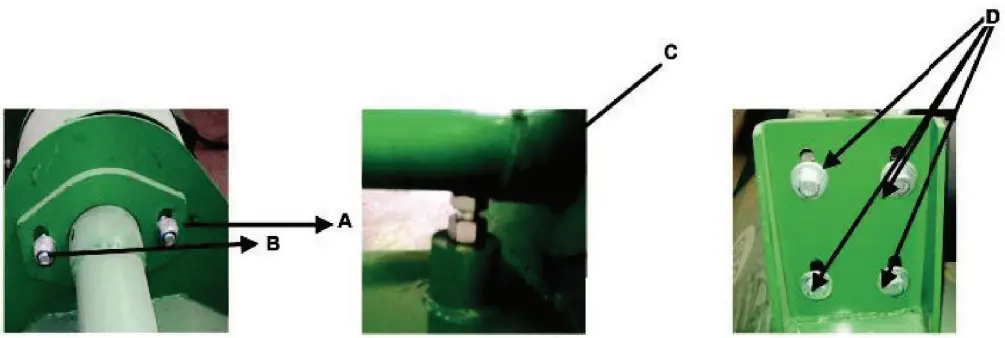
Adjust the drive belt tension. The correct belt tension is achieved when the belt can be deflected by the belt thickness about 10mm at the center point between the pulleys. Align the gearbox so the drive shaft is parallel with the body. Use a straight edge to make sure the belt pullies are in-line and running true. If mis-angled, call your dealer or service agent for technical support. Fit the safety covers and tighten the mounting bolts before operation.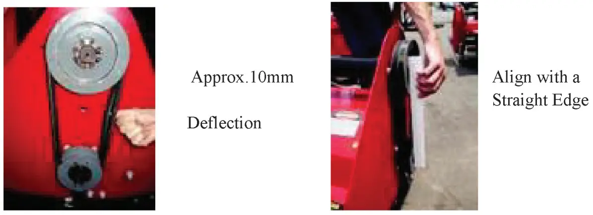
TRANSPORT
WORKING SPEED
The working speed depends on quality, diameter and height of the material to be cut; for efficient mower performance it must be between 2 and 5 MPH. The power take-o_ speed must be 1000 RPM maximum. Operate the mower at its full rated PTO speed to maintain blade speed for a clean cut.
![]() DANGER!
DANGER!
Do not exceed the rated PTO speed for the implement. Excessive PTO speeds can cause driveline or blade failures resulting in serious injury or death.
ROAD TRANSPORT
Extreme caution should be used when transporting the tractor and implement on public roadways.
The tractor must be equipped with all required safety warning features including SMV emblem and flashing warning lights which are clearly visible from the rear of the unit. Make sure you are in compliance with all local regulations regardingtransporting equipment on public roads and highways. Do not exceed 20 MPH (32KPH).
Reduce speed on rough roads and surfaces. Always use hazard flashers on the tractor when transporting unless prohibited by law.
STORAGE
If your shredder will not be used for a long period of time, respect the following suggestions:
- Wash the machine thoroughly and dry it.
- Lubricate all bearings with enough grease to eliminate any cavities where water condensation may occur and cause damage. refer to “Maintenance of the Machine” for location of all grease fittings. Be sure the vent on top of the gearbox is open.
- Loosen the set nut and spindle jack to relieve drive belt tension (NOTE: Before next season’s use, be sure to adjust the drive belt tension).
- Coat all exposed surfaces inside the mower with oil or grease to prevent rusting and pitting during storage. 5. Protect the whole machine with a tarpaulin and put it in a dry place.
PRE-SEASON CHECK
- Check the oil level in the gearbox and lubricate all bearings. See “Lubrication”.
- Adjust drive belt tension. See “Belt Drive”.
- Check all equipment and replace damaged or worn parts.
- Tighten all bolts and nuts (See “Torque Specifications”).
- Inspect for missing and/or broken blades/knives. Replace as necessary. See “Knife Replacement”.
- Be sure that the safety guards are in place. 7. Run the flail mower at low RPM checking to make sure that all driveline parts are moving freely.
MAINTENANCE
Maintenance is a fundamental operation to extend life and performances of any agricultural vehicle; taking care of the machine grants you not only a good work execution, but also a longer life of the whole equipment and a greater safety in the workplace. The operating times indicated in this manual have just an informative character and are referred to normal conditions of use; they can thus undergo variations according to the type of service.
CAUTION!
Before injecting lubricating grease into the zerks, clean them accurately to prevent mud, dust or other foreign matters from mixing up with grease, thus diminishing the lubrication effect. When adding or changing oil, it is better to use the same oil type, in order to avoid mixing oils with different features.
Before executing maintenance activities on the machine, stop engine, disengage power take-off, set parking brake and place the equipment on the ground in horizontal position.
FIRST CHECK
- Check the correct tension of the driving belt.
- Check that all bolts and nuts are tightened.
- After the first 50 hours of work, change oil int he gearbox.
EVERY 8 HOURS OF WORK
- Rotate teardrop shaped plate B and grease the shaft support (driveline side) through the lubricating nipple A (Picture 1).
- Grease the shaft support (external side) through the lubricating zerk A (Picture 2).
- Grease the shaft support (driveline) and the belt tensioner idler pin through the lubricating zerks A and B (Picture 3).
- Grease the stabilizing roller through the lubricating zerk A. (Picture 4).
EVERY 50 HOURS OF WORK
- Check the correct tension of the driving belt.
- Check that all bolts and nuts are tightened.
- Check the cutters/hammers for wear.
- Check the over-gear unit oil level through plug A (Picture 5).
EVERY 500 HOURS OF WORK
- Check that all bolts and nuts are tightened.
- Change oil in the over-gear unit.
EVERY 1000 HOURS OF WORK
- Replace the driving belt.
GEARBOX MAINTENANCE
- The oil should be drained out and replaced after the first 50 hours of operation.
- Then the oil should be changed every 250 hours, or at least once a year.
- Drain oil form the gearbox thoroughly. Check and clean it. Fill with new gear oil up to the dedicated oil level.
- The draining procedure is as follows: remove the draining bolt under the gearbox, so that the oil drains off. After the oil is drained out, put the plug back and fill with gear oil up to the dedicated oil level.
| Maintenance Checklis t | |||||||||
| 8HRS/Daily | 50HRS/Weekly | Annually | |||||||
| Lubricate PTO Shaft | |||||||||
| Lubricate Caster Wheels | |||||||||
| Lubricate Blade Spindle | |||||||||
| Check Gear Box Oil Level | |||||||||
| Clean Machine | |||||||||
| Lubricate & Clean PTO SHaft Cover | |||||||||
PTO SHAFT MAINTENANCE
The PTO shaft is designed to telescope to allow for dimensional changes as the machine goes through its operating range. A tubular guard encloses the driving components and is designed to turn relative to the driving components. The shaft should telescope easily and the guard turn freely on the shaft at all times.
Annual disassembly, cleaning and lubrication is recommended to ensure that all components function as intended.
To maintain the shaft, follow this procedure:
- Remove the shaft from the machine.
- Pull shaft apart.
- Use a screwdriver to pry the tabs out of the sleeves on each end.
- Pull the shaft out of the plastic tubular guard.
- Use a solvent to clean the male and female portions of the telescoping ends.
- Apply a light coat of grease to each end.
- Clean the grooves on each end where the tabs are located.
- Apply a light coat of grease to each groove.
- Insert the shaft into its respective guard and align the slots with the groove.
- Insert the tabs through the slots and seat in the groove.
- Check that each guard turns freely on the shaft.
- Assemble the shaft.
- Check that the shaft telescopes easily.
- Replace any components that are damaged or worn.
- Install the shaft on the machine.
EXPLODED VIEW & PARTS LIST
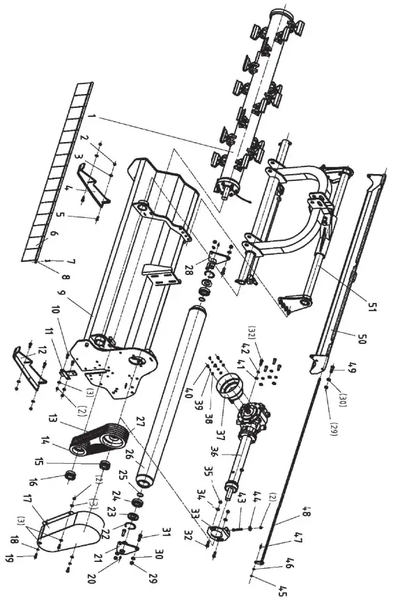
| REF | PART NUM | DESCRIPTION | QTY |
| 1-1 | VM200-DZZJ-PJ | VM (AGM) 200 Blade Axle | 1 |
| 1-2 | VM220-DZZJ-PJ | VM (AGM) 220 Blade Axle | 1 |
| 1-3 | VM240-DZZJ-PJ | VM (AGM) 240 Blade Axle | 1 |
| 2 | GB6184-86 | M12 Nut | 7 |
| 3 | GB97.1-85 | 12 Washer | 6 |
| 4 | EFGC120.013 | Base Plate | 1 |
| 5 | GB5783-86 | M12x40 Bolt | 4 |
| 6 | EFAG140.111 | Fender | 15 |
| 7 | GB91-86 | 4×30 Pin | 2 |
| 8-1 | VM200.101 | (200) Pole | 1 |
| 8-2 | VM220.101 | (220) Pole | 1 |
| 8-3 | VM240.101 | (240) Pole | 1 |
| 9-1 | AGMZ-200.013 | (200) Hood | 1 |
| 9-2 | AGMZ-220.013 | (220) Hood | 1 |
| 9-3 | AGMZ-240.013 | (240) Hood | 1 |
| 10 | GB2673-86 | M12x30 Bolt | 2 |
| 11 | AGMZ-200.017 | Plate | 1 |
| 12 | EFGC120.014 | Base Plate | 1 |
| 13 | 47.171.321 | 17×1321 Belt | 5 |
| 14 | 4J-220H-135 | Pulley | 1 |
| 15 | JB/T7934Z3 | Reach 15 40×80 Sleeve | 1 |
| 16 | JB/T7934Z3 | Reach 15 45×80 Sleeve | 1 |
| 17 | AGMZ-200.016 | Belt Cover | 1 |
| 18 | GB93-87 | 12 Washer | 2 |
| 19 | GB5783-86 | M12x30 Bolt | 3 |
| 20 | GB1152-89 | M10x1 Grease Nipple | 2 |
| 21 | EFAG140.022 | Plate | 1 |
| 22 | GB893.1-86 | 90 Cir Clip | 2 |
| 23 | GB13871-94 | 40x90x10 Oil Seal | 2 |
| 24 | GB/T276-94 | 6308 Bearing | 2 |
| 25 | GB894.1-86 | 40 Cir Clip | 2 |
| 26-1 | EFAG200.017 | (200) Roller | 1 |
| 26-2 | EFAG220.017 | (220) Roller | 1 |
| 26-3 | EFAG240.017 | (240) Roller | 1 |
| 27 | 4J-220H-136 | Big Pulley | 1 |
| 28 | EFAG140.020 | Plate | 1 |
| 29 | GB6184-86 | M16 Locking Nut | 6 |
| 30 | GB97.1-85 | 16 Washer | 6 |
| 31 | GB5783-86 | M16x45 Bolt | 4 |
| 32 | GB5783-86 | M14x40 Bolt | 6 |
| 33 | VM190.108 | Adjusting Plate | 1 |
| 34 | GB97.1-85 | 14 Washer | 2 |
| 35 | GB6184-86 | M14 Nut | 2 |
| 36 | Transmit | 4 | |
| 37 | FM120.00.199C | PTO Cover | 4 |
| 38 | GB97.1-85 | 10 Washer | 4 |
| 39 | GB93-879 | 10 Washer | 4 |
| 40 | GB5783-86 | M10x20 Bolt | 4 |
| 41 | GB96-85 | 14 Washer | 4 |
| 42 | GB93-87 | 14 Washer | 4 |
| 43 | GB5783-86 | M12x80 Bolt | 1 |
| 44 | GB96-85 | 12 Washer | 1 |
| 45 | GB6184-86 | M8 Nut | 1 |
| 46 | GB97.1-85 | 8 Washer | 1 |
| 47 | GB5783-86 | M8x25 Bolt | 1 |
| 48-1 | AGZ-200.017 | (200) Pole | 1 |
| 48-2 | AGZ-220.017 | (220) Pole | 1 |
| 48-3 | AGZ-240.017 | (240) Pole | 1 |
| 49 | GB5783-86 | M16x40 Bolt | 2 |
| 50-1 | AGMZ-200.013 | (200) Rear Plate | 1 |
| 50-2 | AGMZ-220.012 | (220) Rear Plate | 1 |
| 50-3 | AGMZ-240.012 | (240) Rear Plate | 1 |
| 51 | Suspension Bracket | 1 |
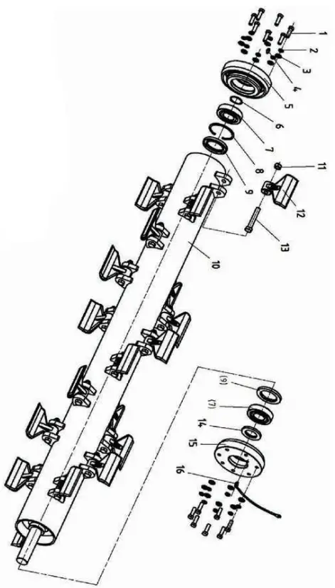
| REF | PART NUM | DESCRIPTION | QTY |
| 1 | GB5783-86 | M12x35 Bolt | 14 |
| 2 | GB93-87 | 12 Washer | 14 |
| 3 | GB97.1-85 | 12 Washer | 14 |
| 4 | GB1152-89 | M6 Grease Nipple | 1 |
| 5 | VM190.110 | Bearing Seat | 1 |
| 6 | GB894.1-86 | 45 Cir Clip | 1 |
| 7 | GB/T281-94 | 1309 Bearing | 2 |
| 8 | GB893.1-86 | 100 Cir Clip | 1 |
| 9 | GB13871-94 | 65x100x10 Oil Seal | 2 |
| 10-1 | VM200.017 | (200) Axle | 1 |
| 10-2 | VM220.017 | (220) Axle | 1 |
| 10-3 | VM240.017 | (240) Axle | 1 |
| 11 | GB6184-86 | M16 Nut | 20 |
| 12 | EFAG140.103 | Hammer | 20 |
| 13 | EFAG140.190 | M16x1.5×92 Bolt | 20 |
| 14 | GB13871-94 | 45x80x8 Oil Seal | 1 |
| 15 | VM190.111 | Bearing Seat | 1 |
| 16 | EFAG140.023 | Pipe | 1 |
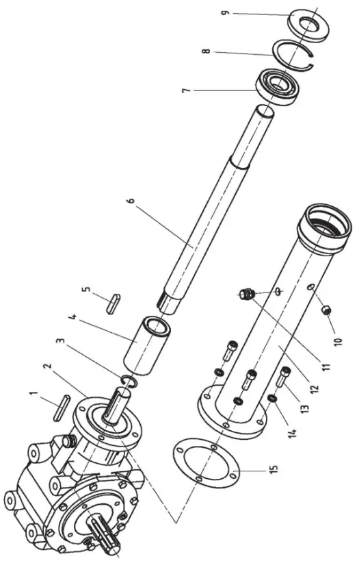
| REF | PART NUM | DESCRIPTION | QTY |
| 1 | GB1096-79 | A10X70 Key | 1 |
| 2 | AG20.01.C00 | Gearbox | 1 |
| 3 | GB893.1-86 | 33 Cir Clip | 1 |
| 4 | G2-150.110 | Sleeve | 1 |
| 5 | GB1096-79 | A12x50 Key | 1 |
| 6 | VM190.109 | Transmit Shaft | 1 |
| 7 | GB/T278-94 | 6308ZZ Bearing | 1 |
| 8 | GB893.1-86 | 90 Cir Clip | 1 |
| 9 | GB13871-94 | 40x90x10 Oil Seal | 1 |
| 10 | ZBT 32001.3-87 | ZG3/8”-19 Bolt | 1 |
| 11 | FM120.00.199A | Bolt | 1 |
| 12 | VM190.020 | PTO Cover | 1 |
| 13 | GB70.1-85 | M12x35 Bolt | 4 |
| 14 | GB93-87 | 12 Washer | 4 |
| 15 | AGM200.130 | Gasket | 1 |
GEARBOX ASSEMBLY
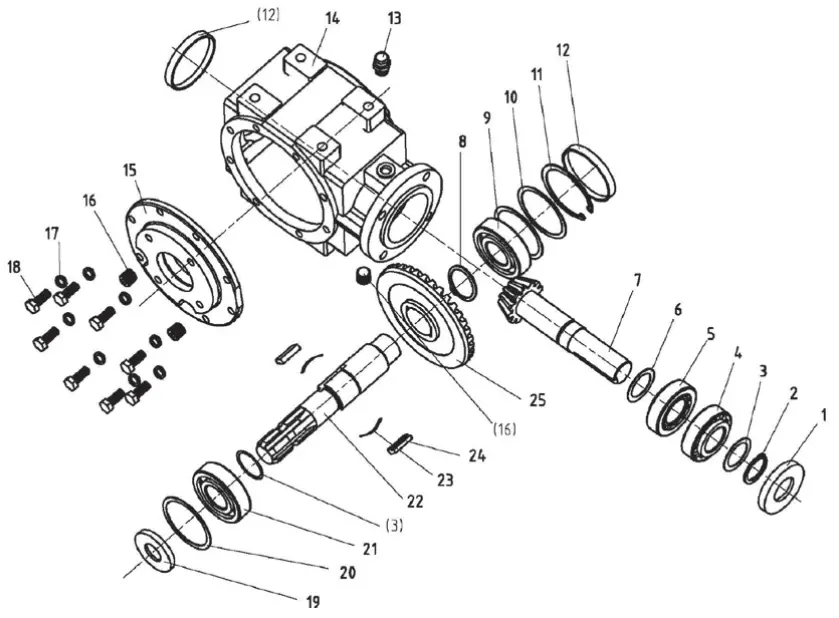
| REF | PART NUM | DESCRIPTION | QTY |
| 1 | CFW-35x80x10 | FB | 1 |
| 2 | JB4342-35(2.5mm) | 1 | |
| 3 | TZDP-48-35-1 | 48x35x1 | 2 |
| 4 | GB297-30307 | 1 | |
| 5 | GB297-32307 | 1 | |
| 6 | TZDP-48-35-2 | 48x35x2 | 1 |
| 7 | AG20.01.C01 | 1 | |
| 8 | GB894.1-42 | A | 1 |
| 9 | GB276-6308 | 1 | |
| 10 | TZDP-90-79-0.4 | 90x79x0.4 | 2 |
| 11 | GB893.1-90 | A | 1 |
| 12 | NFG-RCA-90×10 | 90X10 | 2 |
| 13 | CBW-00-011B | ZG3/8 | 1 |
| 14 | AG20.01.C02 | 311 | 1 |
| 15 | AG20.01.C03 | 311 | 1 |
| 16 | ZBT32001.3-ZG3/8-19” | 3 | |
| 17 | GB96-10 | 8 | |
| 18 | GB5783-M10x25 | 8 | |
| 19 | CFW-35x90x10 | FB | 1 |
| 20 | TZDP-100-89-0.4 | 100x89x0.4 | 2 |
| 21 | GB276-6407 | 1 | |
| 22 | AG20.01.C04 | 1 | |
| 23 | AG14.01.C07 | 3 | |
| 24 | AG14.01.C06 | 3 | |
| 25 | AG14.01.C05 | 1 |
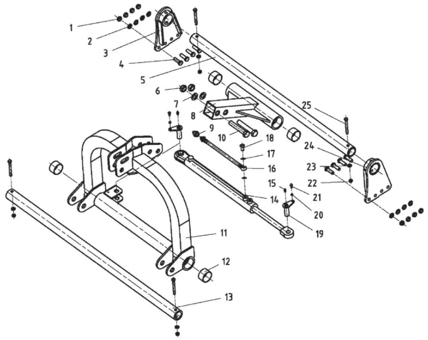
| REF | PART NUM | DESCRIPTION | QTY |
| 1 | GB6184-86 | M16 Nut | 8 |
| 2 | GB97.1-85 | 16 Washer | 8 |
| 3 | AGMZ-200.014 | Plate | 1 |
| 4 | GB5783-86 | M16x50 | 8 |
| 5 | AGZ-200.104 | Rail Guide | 1 |
| 6 | GB6184-86 | M24 Nut | 2 |
| 7 | GB97.1-85 | 24 Washer | 4 |
| 8 | AGZ-200.018 | Tube | 1 |
| 9 | QUICK-COUPLING-G1/2-G | G1/2 Quick Coupling | 1 |
| 10 | GB5782-86 | M24x140 Bolt | 2 |
| 11 | AGMZ-200.011 | Suspension Bracket | 1 |
| 12 | SF-2 | 65x70x40 Bearing | 4 |
| 13 | CBW-00-011B | ZG3/8 | 2 |
| 14 | AGM200.014 | Cylinder | 1 |
| 15 | GB1152-89 | M6 Grease Nipple | 2 |
| 16 | EFAG140.010 | Pipe | 2 |
| 17 | GB3451-83 | 12 Bronze Washer | 4 |
| 18 | GB3451-83 | M12x1.25 Bolt | 2 |
| 19 | EFAGL125.103 | Pin | 2 |
| 20 | GB93-87 | 8 Washer | 2 |
| 21 | GB5783-86 | M8x16 Bolt | 2 |
| 22 | GB6184-86 | M12 Nut | 4 |
| 23 | GB97.1-85 | 12 Washer | 4 |
| 24 | AGMZ-200.015 | Plate | 1 |
| 25 | GB5782-86 | M12x110 Bolt | 4 |
PHONE: 604-850-7770
FAX: 604-850-7774
TOLL FREE PHONE: 1-877-588-3311
TOLL FREE FAX: 1-800-665-7334