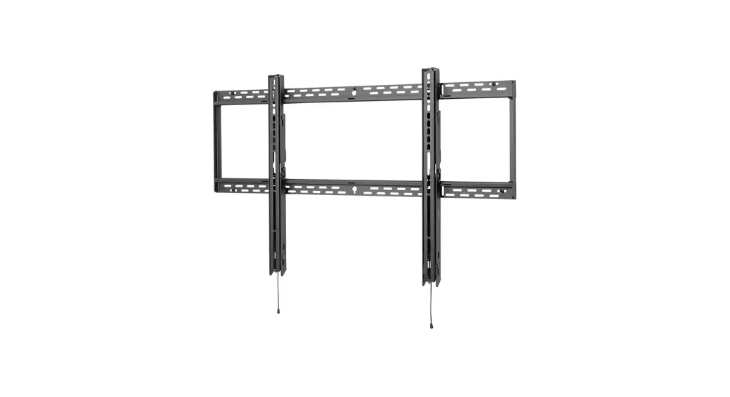
![]() SF680P-HUB2 Flat TV Wall Mount
SF680P-HUB2 Flat TV Wall Mount
Installation Guide
SF680P-HUB2 Flat TV Wall Mount
| 85″ (215 cm) | 350 lb (159 kg) |
![]() WARNING
WARNING
This product is designed to be installed on wood stud, solid concrete or cinder block walls. Hardware is included for wood stud, solid concrete and cinder block installation. Before installing make sure the supporting surface will support the combined load of the equipment and hardware. Screws must be tightly secured. Do not overtighten screws or damage can occur and product may fail. Never exceed the Maximum Load Capacity. Always use an assistant or mechanical lifting equipment to safely lift and position equipment. This product is intended for indoor use only. Use of this product outdoors could lead to product failure or personal injury. Be careful not to pinch fingers when operating the mount. For support please call customer care at 1-800-865-2112.
Symbols
| WARNING | |
 | Do not overtighten screws. |
| Listen | |
| Skip to step. | |
 | Display center. |
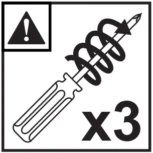 | Screws must get at least three full turns and fit snug. |
Tools Needed for Assembly
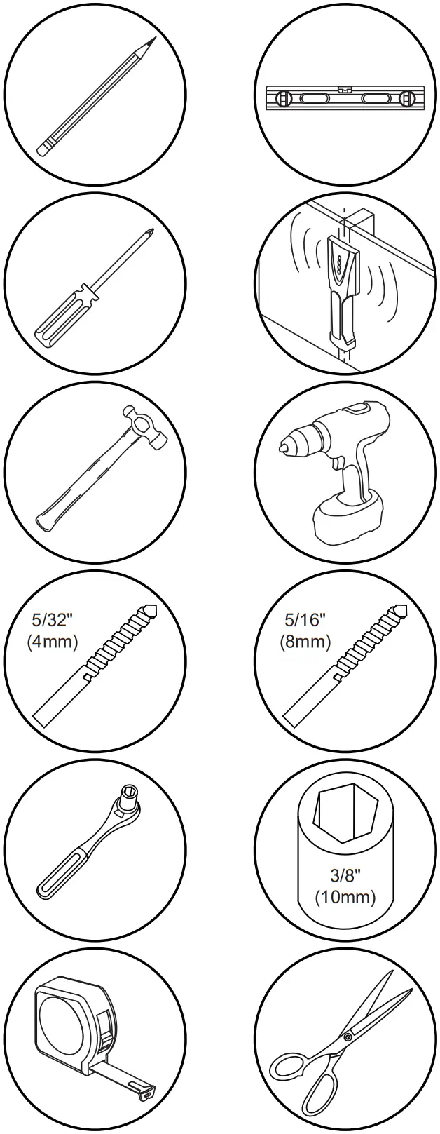
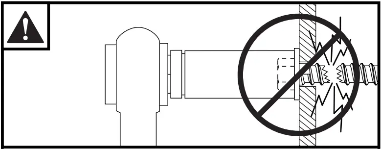
![]() To properly tighten screws: Tighten until screw head makes contact, then tighten another 1/2 turn. Do not overtighten screws.
To properly tighten screws: Tighten until screw head makes contact, then tighten another 1/2 turn. Do not overtighten screws.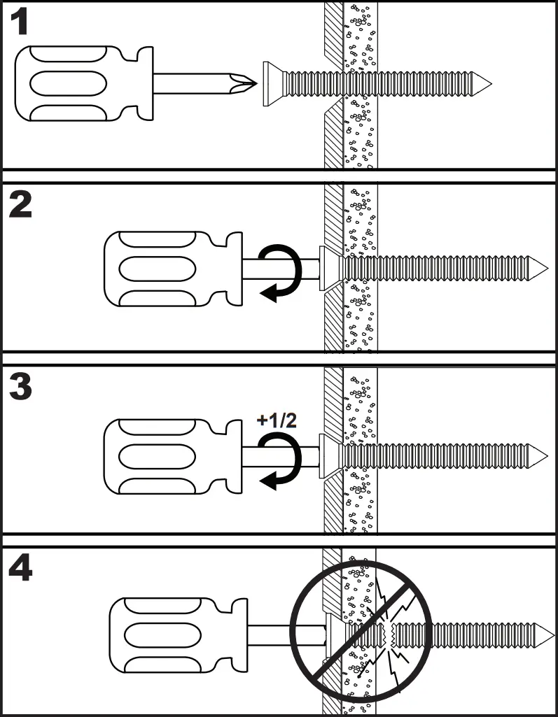
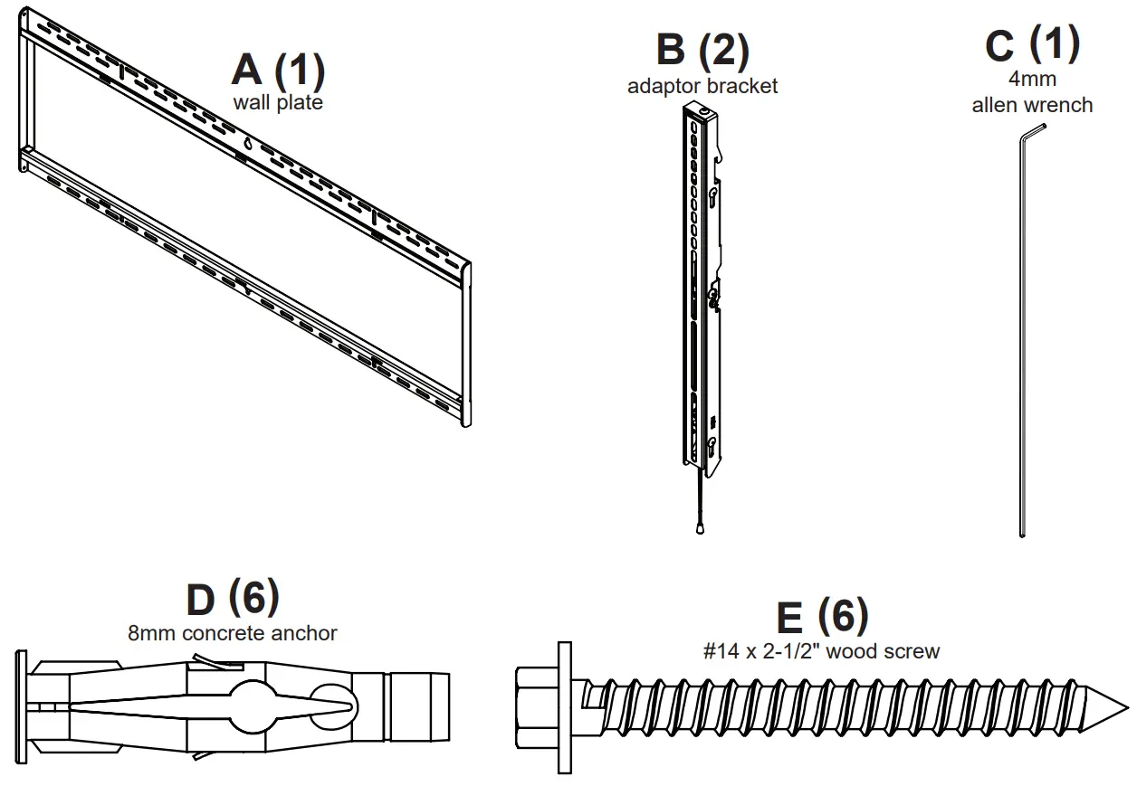
Parts
(Before beginning, make sure you have all parts shown below).
| Parts List Description | Qty | SF680P-HUB2 Part # |
| A wall plate | 1 | 096-SG1588 |
| B adaptor bracket | 2 | 096-SG1582 |
| C 4mm allen wrench | 1 | 560-1145 |
| D 8mm concrete anchor | 6 | 590-0320 |
| E #14 x 2.5″ wood screw | 6 | 5S1-015-C03 |
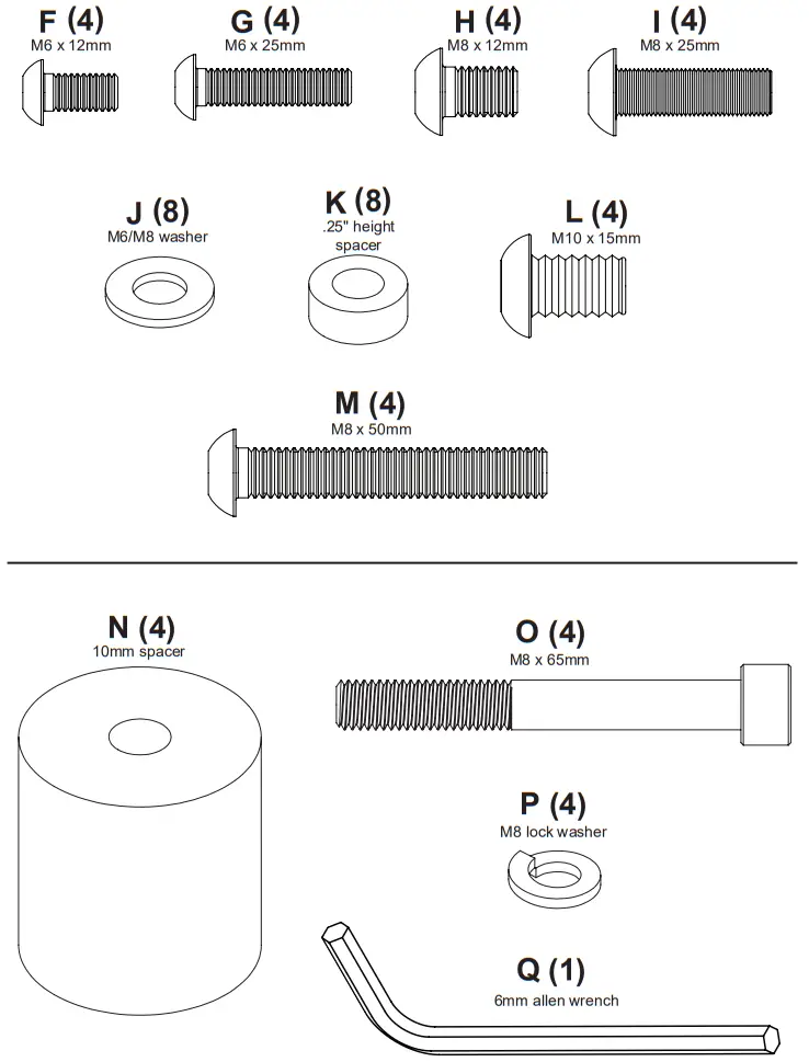
| F M6 x 12mm (not used) | 4 | 520-1128 |
| G M6 x 25mm (not used) | 4 | 520-1208 |
| H M8 x 12mm (not used) | 4 | 520-9571 |
| I M8 x 25mm (not used) | 4 | 520-1031 |
| J M6/M8 washer (not used) | 8 | 540-9406 |
| K .25″ height spacer (not used) | 8 | 600-1215 |
| L M10 x 15mm (not used) | 4 | 520-1305 |
| M M8 x 50mm (not used) | 4 | 521-1009 |
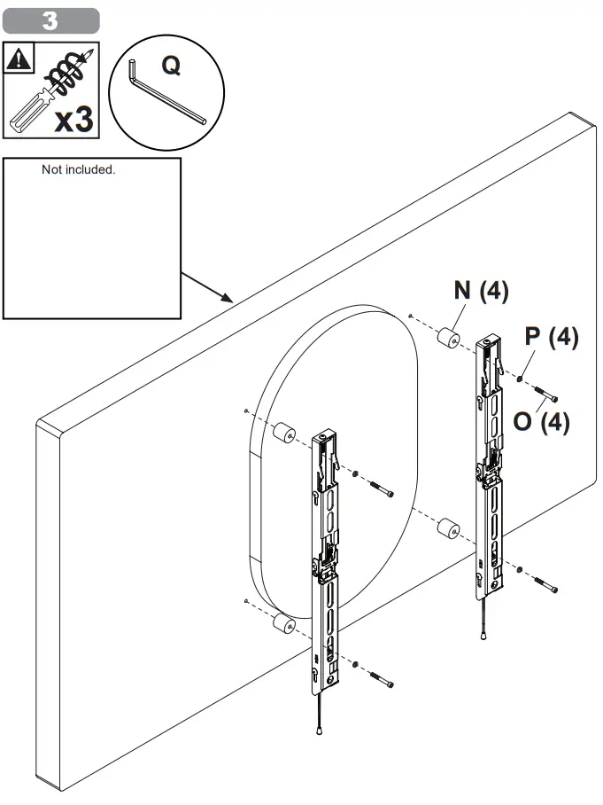
| N 10mm spacer | 4 | 10004495 |
| O M8 x 65mm screw | 4 | 10004807 |
| P M8 lock washer | 4 | 10004497 |
| Q 6mm allen wrench | 1 | 560-9716 |
 Wood stud wall.
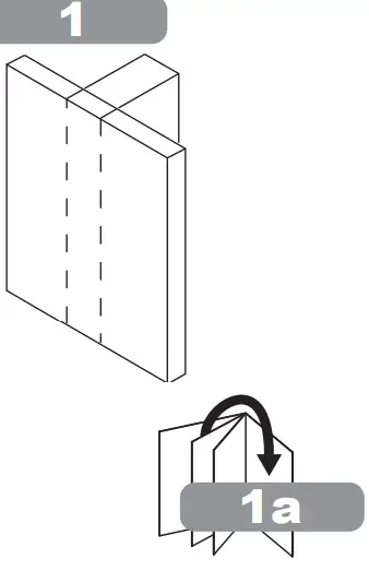 Concrete/Cinder block.
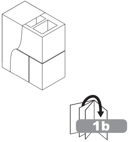 1a.
1a.![]() WARNING
WARNING
When installing Peerless wall mounts on a wood stud wall covered with gypsum board (drywall), verify that the wood studs are a minimum of 2″ x 4″ nominal size. Do not install over gypsum board thicker than 5/8″.
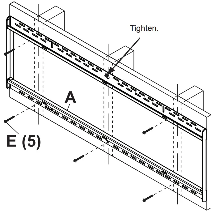
Use stud finder to locate and mark stud center lines.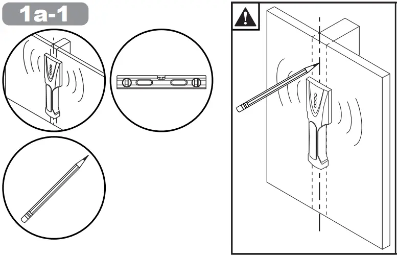 Level wall plate. Mark mounting holes on stud center lines. Wall plate must be centered on middle stud as shown.
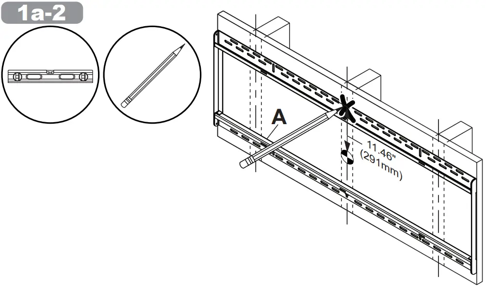 Drill mounting holes into supporting surface (2.5″ (64mm) minimum depth required).
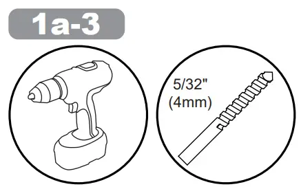 Mounting hole must center on stud.
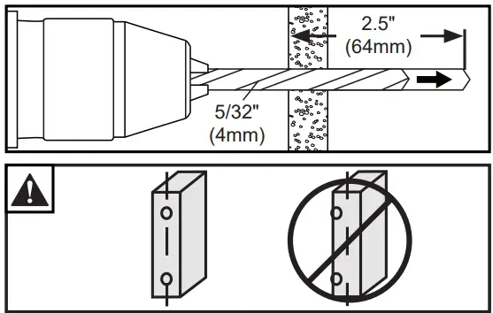
 Level wallplate. Mark mounting holes on stud center lines. Wallplate must be centered on middle stud as shown.
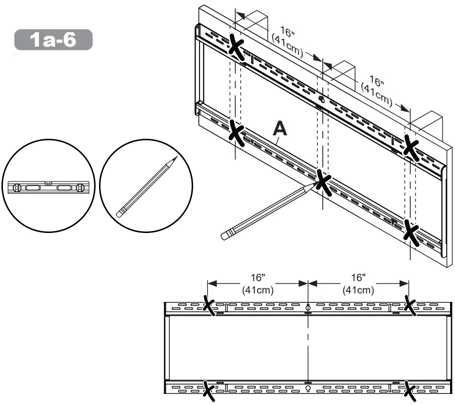 Drill mounting holes into supporting surface (2.5″ (64mm) minimum depth required).
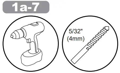 Mounting hole must center on stud.
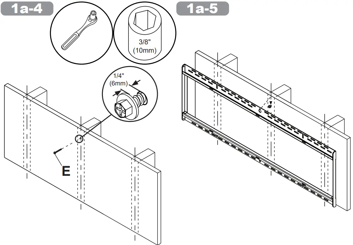
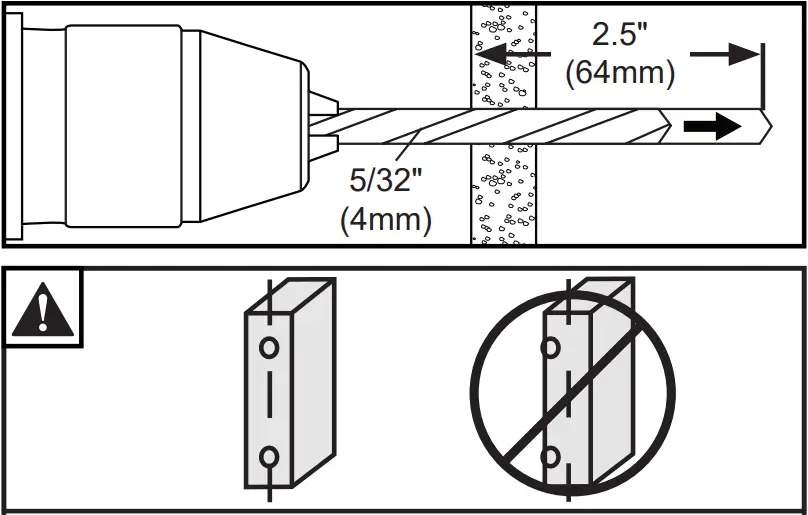 Level wallplate. Install using wood screws provided.
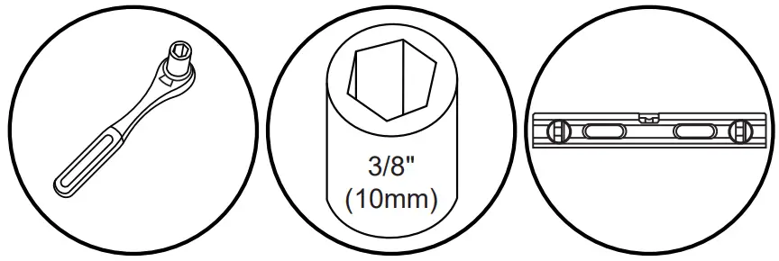 Maximum 80 in. • lb (9 N.M.).
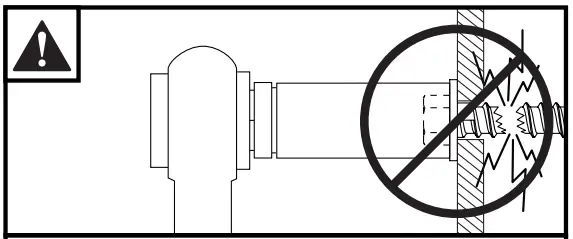
 1b.
1b.![]() WARNING
WARNING
When installing Peerless wall mounts on a concrete wall, the wall must be at least 8″ thick with a minimum compressive strength of 2000 psi. When installing Peerless wall mounts on a cinder block wall, the cinder blocks must meet ASTM C-90 specifications and have a minimum nominal width of 8″. Do not drill into mortar joints! Be sure to mount in a solid part of the block, generally 1″ (25 mm) minimum from the side of the block. It is suggested that a standard electric drill on slow setting is used to drill the hole instead of a hammer drill to avoid breaking out the back of the hole when entering a void or cavity. Never attach concrete expansion anchors to concrete or cinder block covered with plaster, drywall or other finishing material.
Level wallplate. Mark mounting holes.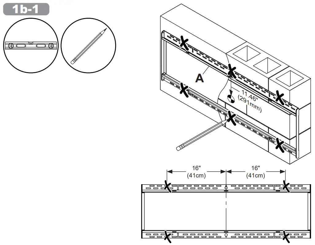 Drill mounting holes into supporting surface (2.5″ (64mm) minimum depth required).
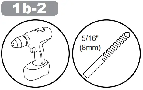 Do not drill into mortar joints.
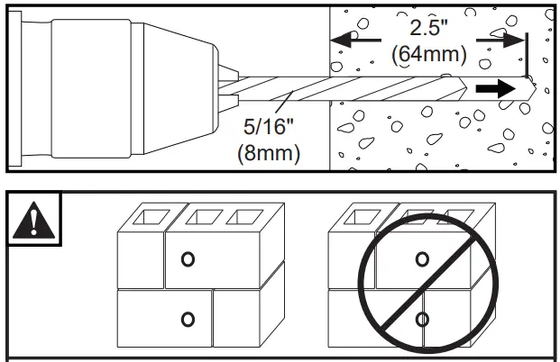 Insert anchor flush to concrete.
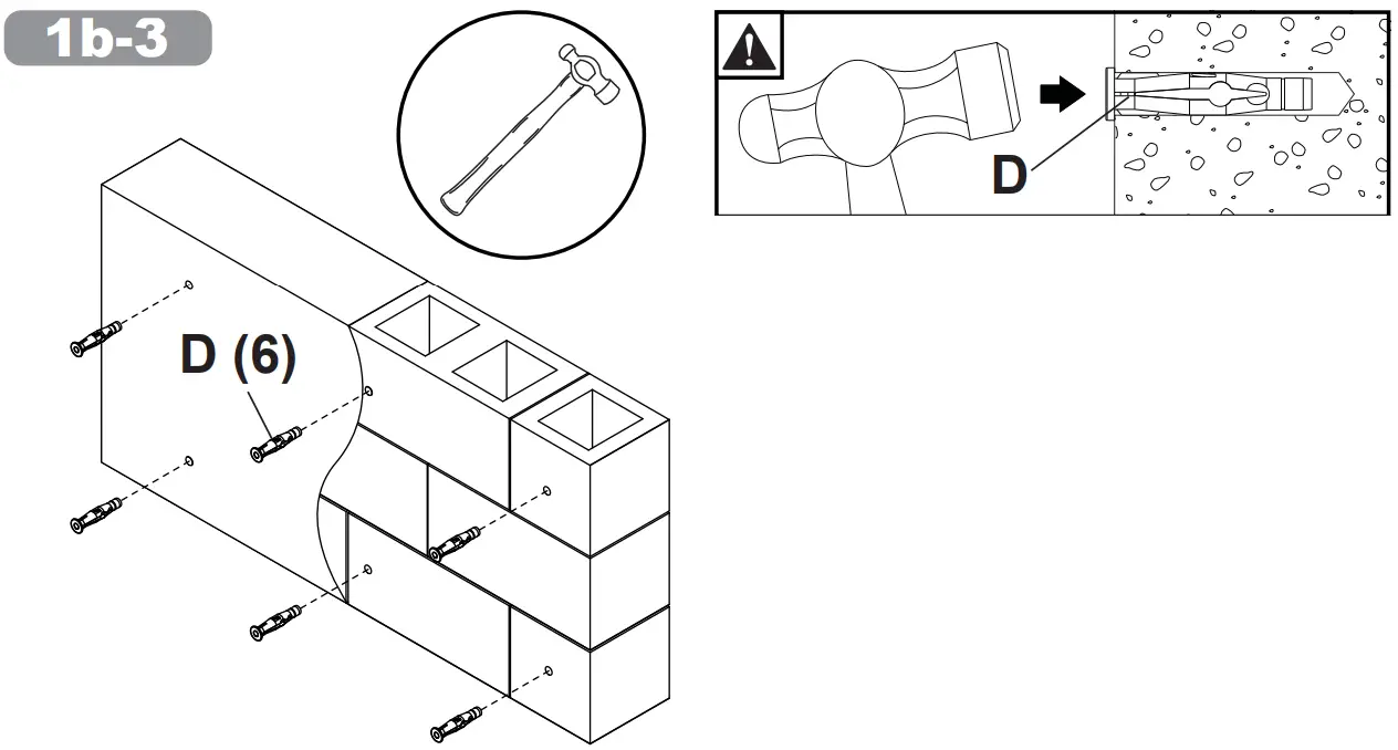 Level wallplate. Install using concrete anchors and wood screws provided.
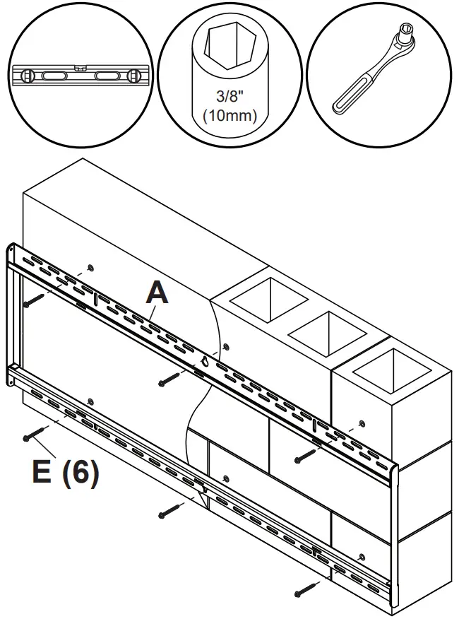 Maximum 80 in. • lb (9 N.M.).
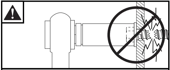 2. Center adaptor brackets vertically on back of screen.
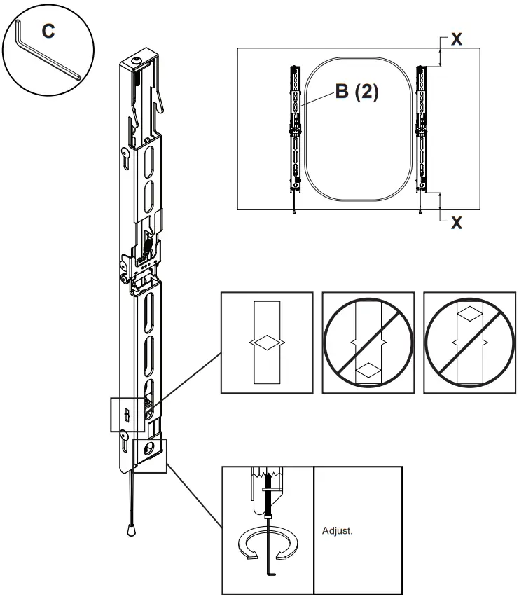
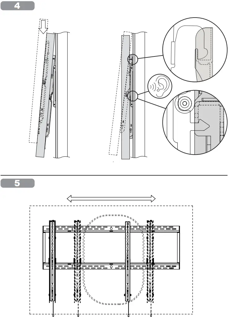 Height adjustment: Tighten or loosen.
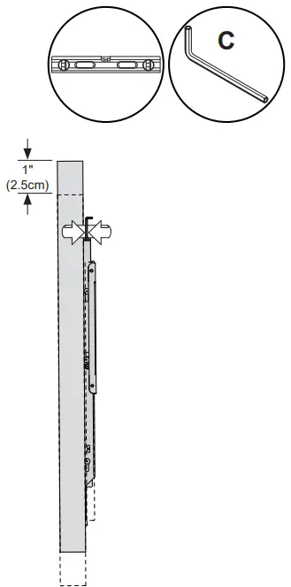 7.
7.![]() WARNING
WARNING
Do not bump screen while adapter brackets are disengaged, or screen may fall.
Kickstand is for maintenance only.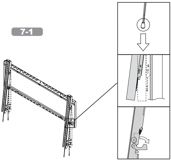 Optional: Cable management.
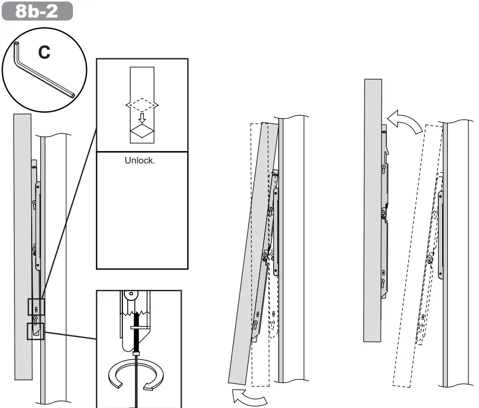
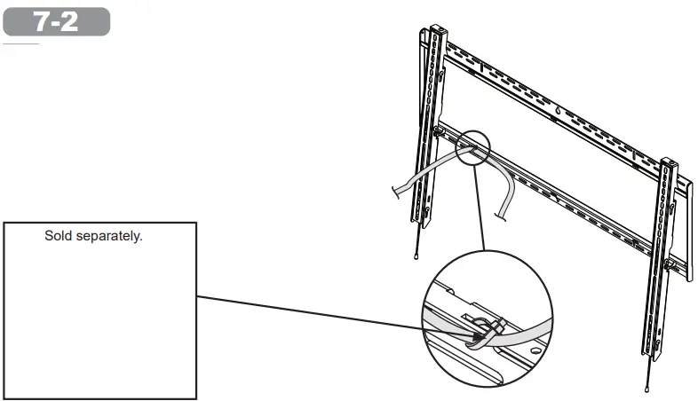 Re-engage the display.
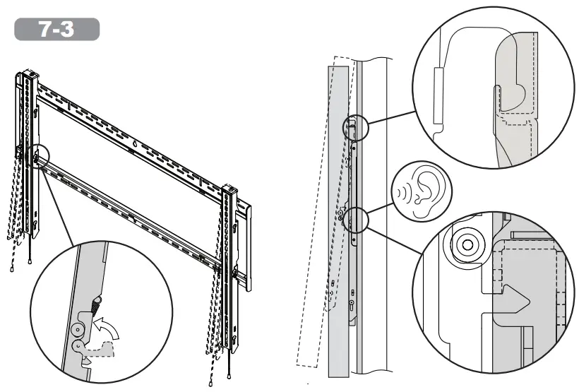 Optional: Remove display.
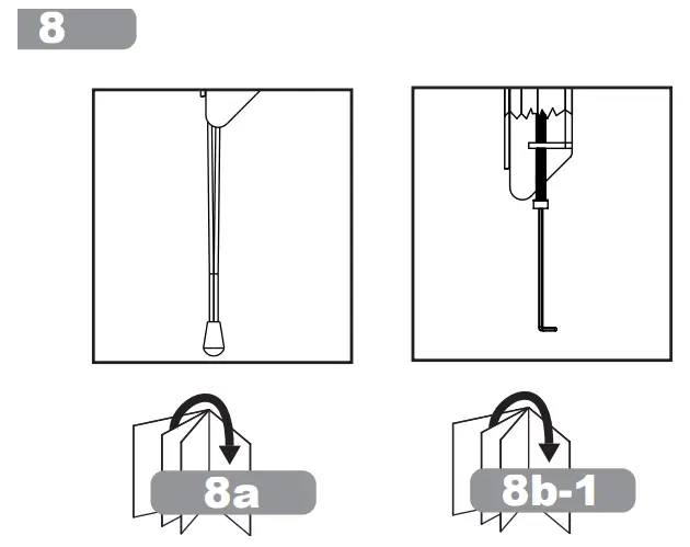
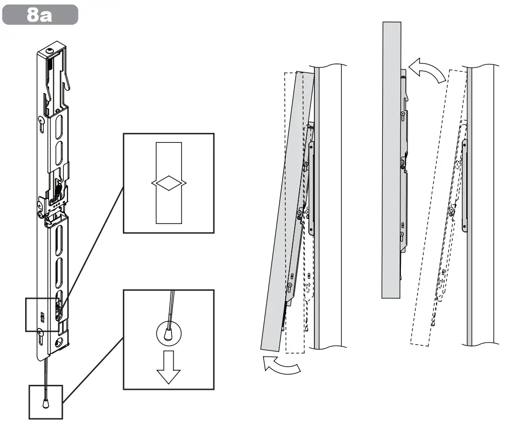 Caution: If removing quick-release string, allen wrench required to remove display.
 Optional
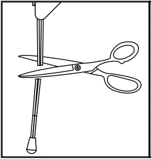
Warranty
| Peerless-AV 2300 White Oak Circle Aurora, IL 60502 Email: [email protected] Ph: (800) 865-2112 Fax: (800) 359-6500 www.peerless-av.com © 2021, Peerless Industries, Inc. | Peerless-AV Europe Unit 3 Watford Interchange, Colonial Way, Watford, Herts, WD24 4WP, United Kingdom Customer Care 44 (0) 1923 200 100 www.peerless-av.com © 2021, Peerless Industries, Inc. | Peerless-AV América Latina Av. de las Industrias 413 Parque Industrial Escobedo General Escobedo N.L., México 66062 Servicio al Cliente 01-800-849-65-77 www.peerless-av.com © 2021, Peerless Industries, Inc. |
© 2021 Microsoft. Microsoft, the Microsoft logo, Microsoft Surface, Surface, and the Microsoft Surface logo are trademarks of the Microsoft group of companies. All other trademarks are the property of their respective owners.
![]() 2021-11-15 #:204-9131-1
2021-11-15 #:204-9131-1


