LANCOM OW-602 System GmbH
Mounting
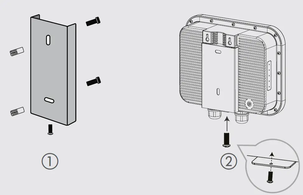
Wall mounting
Use the mounting plate O as a drilling template to mark the drill holes in a suficiently load-bearing wal. After setting the dowels, align the mounting plate and then fasten it to the wall using the provided M6 screws. Then position the access point in front of the mounting plate as shown in the graphic and slide it down the guide. Then screw the locking screw from below through the mounting plate into the housing of the access point and tighten it.
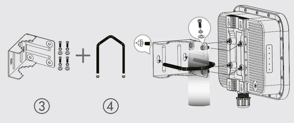
Pole mounting
First, screw the angle bracket to the access point housing using the provided screws. Note the positioning of the washers and lock washers directly under the screw head. Then position the angle bracket with the screwed-on access point on the mast, guide the bracket around the mast through the holes of the angle bracket and fasten it with the enclosed nuts after aligning the access point.+
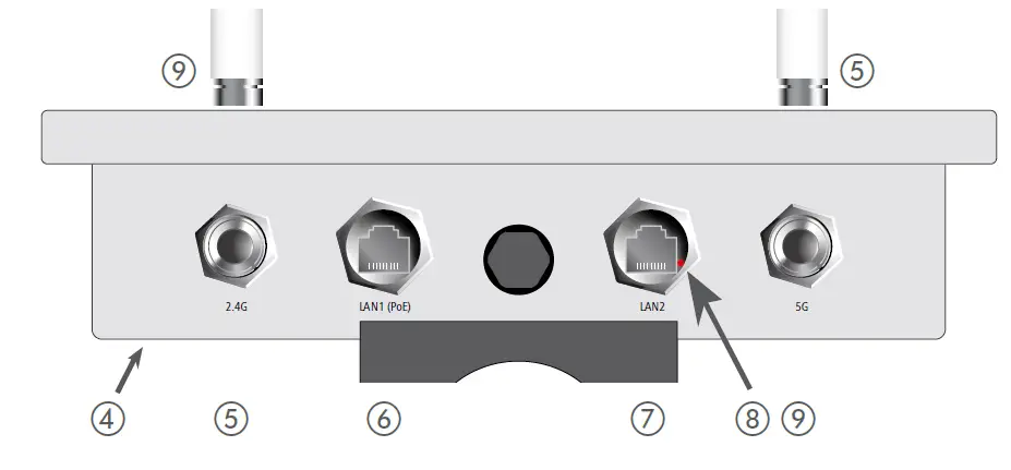
- Ground connection (bottom of the device)
Attach the enclosed grounding cable to the housing on one side with the enclosed M3 screw and to a suitable grounding conductor on the other side. - Antenna connectors 2.4 GHz
Screw the supplied 2.4 GHz antennas to the connectors labeled ‚2.4G‘ on the front and back of the device.
- Ethernet interfaces LAN1 (PoE) / LAN2
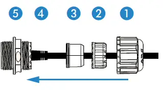
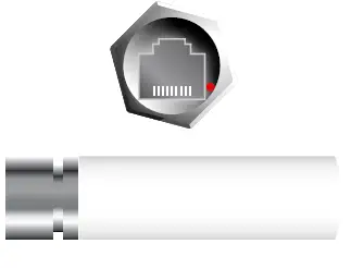
The LAN1 (PoE) port supplies power to the device as well. Prepare to mount the waterproof Ethernet cable by sliding the end cap A and then the clamp ring B over the Ethernet connector D on the cable as shown in the adjacent figure. Then place the two seal halves C between plug D and clamp ring B on the cable and join them together. Next, insert plug D into LAN1 connector E on the device, carefully push all previously assembled parts towards plug D and screw the end cap A to LAN1 connector E on the device. Outdoor cable diameter: 6.5 mm to 8.5 mm Connect the other end of the network cable to the ‚Power-Out‘ port of a suitable PoE injector. If required, additionally connect the LAN2 interface to another network device via a waterproof Ethernet cable.
- Reset button (accessible through the housing of the LAN2 socket)
To restore the default device configuration, use a suitable pointed object to carefully press the reset button in the device through the recess in the housing of the LAN2 socket until the LEDs on the side of the device go out. During the restart that now follows automatically, the device loads the default configuration. - Antenna connectors 5 GHz
Screw the supplied 5 GHz antennas to the connectors labeled ‚5G‘ on the front and back of the device.

Please observe the following when setting up the device
- The housing of the device may become warm during operation.
- If the device is operated with outside temperatures exceeding 60 °C, it should be mounted with protection against contact.
- When using customized outdoor Ethernet cables, make sure that the cables have a short plug kink protection.
Before initial startup, please make sure to take notice of the information regarding the intended use in the enclosed installation guide! Operate the device only with a professionally installed power supply at a nearby power socket that is freely accessible at all times.
CONNECTING THE DEVICE
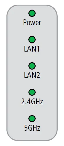
| Power | |
| Off | Device switched off |
| Green, permanently* | Device operational, resp. device paired / claimed and LANCOM Management Cloud (LMC) accessible |
| 1x green inverse blinking* | Connection to the LMC active, pairing OK, device not claimed |
| 2x green inverse blinking* | Pairing error, resp. LMC activation code not available |
| 3x green inverse blinking* | LMC not accessible, resp. communication error |
| LAN1 / LAN2 | |
| Off | No networking device attached |
| Green, permanently | Connection to network device operational, no data traffic |
| Green, flickering | Data traffic |
| 2.4GHz / 5GHz | |
| Off | No Wi-Fi network defined or Wi-Fi module deactivated. The Wi-Fi module is not transmitting beacons. |
| Green | At least one Wi-Fi network is defined and Wi-Fi module activated. The Wi-Fi module is transmitting beacons. |
| Green, blinking | DFS scanning or other scan procedure |
| Hardware | |
| Power supply | Via Power-over-Ethernet compliant to IEEE 802.3at |
| Power consumption | 15.2 W via PoE |
| Environment | -30 °C to +65 °C |
| Housing | Robust plastic housing, protection class IP 67, for wall and pole mounting. Note: For installation in salt water environments please use a suitable outer housing. Dimensions 250 × 200 × 80 mm (depth x width x height) |
| Wi-Fi | |
| Frequency bands | 2.4 GHz and 5 GHz (restrictions vary between countries) |
| Minimum transmission power | Transmission-power reduction in software by 1 dB steps to min. 0.5 dBm |
| Bluetooth Low Energy | The device can detect BLE devices in the neighborhood and forward the data to external systems for analysis. |
| Interfaces | |
| LAN1 (PoE) | 10 / 100 / 1000 Mbps auto-sensing, PoE as per IEEE 802.3at |
| LAN2 | 10 / 100 / 1000 Mbps autosensing |
| Wi-Fi | 4 NJ ports (2 for 2.4 GHz Wi-Fi module, 2 for 5 GHz Wi-Fi module); BLE: internal antenna |
| Declaration of conformity | |
| Hereby, LANCOM Systems GmbH | Adenauerstrasse 20/B2 | D-52146 Wuerselen, declares that this device is in compliance with Directives 2014/30/EU, 2014/53/EU, 2014/35/EU, 2011/65/EU, and Regulation (EC) No. 1907/2006. The full text of the EU Declaration of Conformity is available at the following Internet address: | |
| Package content | |
| Documentation | Quick Reference Guide (DE/EN), Installation Guide (DE/EN) |
| Antennas | 4 external dipole single-band Wi-Fi antennas (2 for 2.4 GHz and 2 for 5 GHz) |
| Mounting kit | Equipment for wall and pole mounting, screws included; grounding cable |
Federal Communication Commission Interference Statement
This device complies with Part 15 of the FCC Rules. Operation is subject to the following two conditions: (1) This device may not cause harmful interference, and (2) this device must accept any interference received, including interference that may cause undesired operation. This equipment has been tested and found to comply with the limits for a Class B digital device, pursuant to Part 15 of the FCC Rules. These limits are designed to provide reasonable protection against harmful interference in a residential installation. This equipment generates, uses and can radiate radio frequency energy and, if not installed and used in accordance with the instructions, may cause harmful interference to radio communications. However, there is no guarantee that interference will not occur in a particular installation. If this equipment does cause harmful interference to radio or television reception, which can be determined by turning the equipment off and on, the user is encouraged to try to correct the interference by one of the following measures:
- Reorient or relocate the receiving antenna.
- Increase the separation between the equipment and receiver.
- Connect the equipment into an outlet on a circuit different from that to which the receiver is connected.
- Consult the dealer or an experienced radio/TV technician for help.
FCC Caution: Any changes or modifications not expressly approved by the party responsible for compliance could void the user’s authority to operate this equipment. This transmitter must not be co-located or operating in conjunction with any other antenna or transmitter.
Radiation Exposure Statement:
This equipment complies with FCC radiation exposure limits set forth for an uncontrolled environment. This equipment should be installed and operated with a minimum distance 20cm between the radiator & your body. Installation location. The product shall be installed at a location where the radiating antenna can be kept 20cm from a nearby person in normal operating conditions to meet regulatory RF exposure requirements.


