![]() SECURE NETWORKS
SECURE NETWORKS
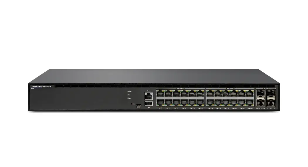
LANCOM GS-4530X
 Quick Reference Guide
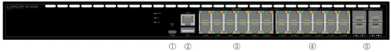
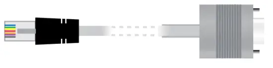
- Configuration interfaces RJ-45 & micro USB (Console)
 Connect the configuration interface via the included micro USB cable to the USB interface of the device you want to use for configuring/monitoring the switch. Alternatively, use the RJ-45 interface with the provided serial configuration cable.
 - USB interface
 Connect a USB stick to the USB interface to store general configuration scripts or debug data.
You can also use this interface to upload new firmware. - TP Ethernet interfaces 10M / 100M / 1G
 Connect the interfaces 1 to 12 via Ethernet cable to your PC or a LAN switch.
 - TP Ethernet interfaces 100M / 1G / 2.5G
 Connect the interfaces 13 to 24 via Ethernet cable with at least CAT5e / S/FTP standard to your PC or a LAN switch.
 - SFP+ interfaces 1G / 10G
 Insert suitable LANCOM SFP modules into the SFP+ interfaces 25 to 28.
Choose cables that are compatible with the SFP modules and connect them as described in the SFP modules mounting instructions: www.lancom-systems.com/SFP-module-MI.
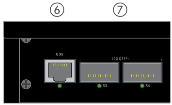
- OOB interface (rear panel)
Use an Ethernet cable to connect this out-of-band service port for an IP interface independent of the switching plane for management tasks or connection to a monitoring server. - QSFP+ interfaces 40G (rear panel)
Plug suitable LANCOM QSFP+ modules into the QSFP+ interfaces 29 and 30. Select cables suitable for the QSFP+ modules and connect them as described in the SFP modules mounting instructions: www.lancom-systems.com/SFP-module-MI. - Power connector (rear panel)
Supply power to the device via the power connector. Please use the IEC power cable supplied or a country-specific LANCOM Power Cord. - An additional slot for the power supply module with mains connection socket (rear panel)
To install an additional power supply module, remove the appropriate module slot cover by loosening both associated screws and inserting the power supply module.
Supply the device with voltage via the power supply module mains connector. Use the supplied power cord (not for WW devices) or a country-specific LANCOM Power Cord.
To remove a power supply module, disconnect the device from the power supply and pull the power plug out of the module. Then push the release lever J to the left. Now you can pull the module out of the device by the handle K.
 Connect the configuration interface via the included micro USB cable to the USB interface of the device you want to use for configuring/monitoring the switch. Alternatively, use the RJ-45 interface with the provided serial configuration cable.
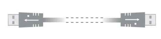 Connect a USB stick to the USB interface to store general configuration scripts or debug data.
 Connect the interfaces 1 to 12 via Ethernet cable to your PC or a LAN switch.
 Connect the interfaces 13 to 24 via Ethernet cable with at least CAT5e / S/FTP standard to your PC or a LAN switch.
 Insert suitable LANCOM SFP modules into the SFP+ interfaces 25 to 28.
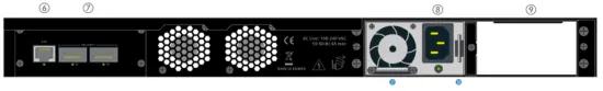
![]() Please observe the following when setting up the device
Please observe the following when setting up the device
- The main plug of the device must be freely accessible.
- For devices to be operated on the desktop, please attach the adhesive rubber footpads.
- Do not rest any objects on top of the device and do not stack multiple devices.
- Keep the ventilation slots on the side of the device clear of obstruction.
- Mount the device into a 19” unit in a server cabinet using the provided screws and mounting brackets.
Both slide-in rails are attached as shown in the accompanying installation instructions www.lancom-systems.com/slide-in-MI. - Please note that support for third-party accessories (SFP and DAC) is not provided.
Before initial startup, please make sure to take notice of the information regarding the intended use in the enclosed installation guide!
Operate the device only with a professionally installed power supply at a nearby power socket that is freely accessible at all times.
MOUNTING AND CONNECTING THE DEVICE
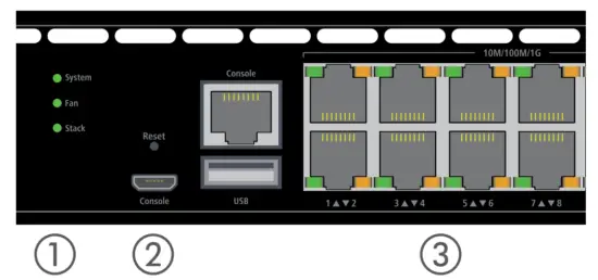
- System / Fan / Stack
System: green Device operational System: red Hardware error Fan: red Fan error Stack: green As a manager: port activated and connected with standby manager connected Stack: orange As standby manager: port activated and connected to the connected manager - Mode / Reset button
~5 sec. pressed Device restart 7~12 sec. pressed Configuration reset and device restart - TP Ethernet ports 10M / 100M / 1G
Off Port inactive or disabled Green Link 1000 Mbps Green, blinking Data transfer, link 1000 Mbps Orange Link < 1000 Mbps Orange, blinking Data transfer, link < 1000 Mbps - TP Ethernet ports 100M / 1G / 2.5G
Off Port inactive or disabled Green Link 2500 – 1000 Mbps Green, blinking Data transfer, link 2500 – 1000 Mbps Orange Link < 1000 Mbps Orange, blinking Data transfer, link < 1000 Mbps - SFP+ ports 1G / 10 G
Off Port inactive or disabled Green Link 10 Gbps Green, blinking Data transfer, link 10 Gbps Orange Link 1 Gbps Orange, blinking Data transfer, link 1 Gbps - OOB port
Off OOB port inactive Green Link 1000 Mbps - QSFP+ ports 40 G
Off Port inactive or disabled Green Link 40 Gbps Green, blinking Data transfer, link 40 Gbps 
Hardware
| Power supply | Exchangeable power supply (110-230 V, 50-60 Hz) |
| Power consumption | Max. 72 W |
| Environment | Temperature range 0–40° C; short-term temperature range 0-50° C; humidity 10–90 %, non-condensing |
| Housing | Robust metal housing, 1 HU with removable mounting brackets and slide-in rails, network connections at front and rear, dimensions 442 x 44 x 375 mm (W x H x D) |
| Number of fans | 2 |
Interfaces
| QSFP+ | 2 * QSFP+ 40 Gbps uplink ports for connection to superordinate core switches or content servers, can also be configured as stacking ports via software |
| TP Ethernet | 12 TP Ethernet ports 10 / 100 / 1000 Mbps 12 TP Ethernet ports 100 / 1000 / 2500 Mbps |
| SFP+ | 4 * SFP+ 1 / 10 Gbps, uplink ports for connection to superordinate core switches or content servers, can also, be configured as stacking ports via software |
| Console | 1 * RJ-45 / 1 * Micro USB |
| USB | 1 * USB host |
| ROB | 1 * ROB |
Declaration of Conformity
Hereby, LANCOM Systems GmbH | Adenauerstrasse 20/B2 | D-52146 Wuerselen, declares that this device is in compliance with Directives 2014/30/EU, 2014/35/EU, 2011/65/EU, and Regulation (EC) No. 1907/2006. The full text of the EU Declaration of Conformity is available at the following Internet address: www.lancom-systems.com/doc
Package Content
| Manual | Quick Reference Guide (DE/EN), Installation Guide (DE/EN) |
| Mounting brackets | Two 19“ mounting brackets, two slide-in rails for rear stabilization in 19“ racks |
| Power supply | 1x exchangeable power supply LANCOM SPSU-250, expandable to 2 LANCOM SPSU-250 power supplies (hot-swappable, for redundancy operation) |
| Cables | 1 IEC power cord, 1 serial configuration cable, 1 micro USB configuration cable |
![]() LANCOM, LANCOM Systems, LCOS, LAN community, and Hyper Integration are registered trademarks.
LANCOM, LANCOM Systems, LCOS, LAN community, and Hyper Integration are registered trademarks.
All other names or descriptions used may be trademarks or registered trademarks of their owners.
This document contains statements relating to future products and their attributes.
LANCOM Systems reserves the right to change these without notice.
No liability for technical errors and/or omissions. 111670/1221


