![]() Hardware Quick Reference
Hardware Quick Reference
LANCOM IAP-5G

Mounting & connecting
 Wall mounting
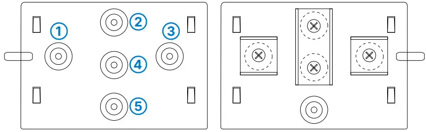
Use the supplied screws to fix the back plate to the wall using the holes ➀, ➂, and ➄.
Top-hat rail mounting (with the separately available IAP Mount, item no. 61647) Using the supplied screws, attach the twotophat rail clips to the holes ➀ and ➂. Do not yet tighten the screws completely; leave some space to adjust the alignment of the clips. Snap the two top-hat rail clips onto the required position on the top-hat rail.
Pole mounting (with the separately available IAP Mount, item no. 61647)
For pole mounting, use the supplied screws to fix the clamp profile through the holes ➁ and ➃.
Place the enclosed mounting clamp or a mounting clamp suitable for your pole diameter around the clamping profile. Then mount the device with the mounting clamp at the desired position on the pole.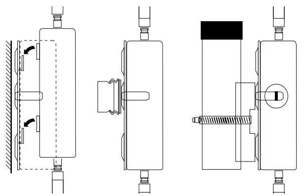 Snap the housing of the device with the four rear openings into the tabs of the base plate.
Optional: Secure with a Kensington lock
The left side of the device features a slot for a Kensington lock. The Kensington lock securely fixes the device to the mounting plate.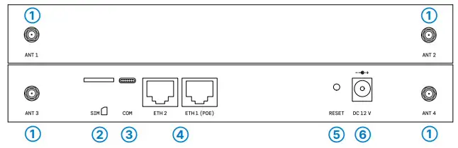
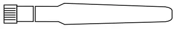
- 5G antenna connectors
Screw the supplied antennas to the connectors ANT 1 – ANT 4.
- Micro SIM card slot
When inserting the SIM card, pay attention to the marking for the correct position. Make sure that the card clicks into place in the slot.
To remove the card, press it lightly into the slot. This releases the card from the locked position in the slot.
- USB-C configuration interface
A USB-C cable is required to configure the device. (Cable not included)
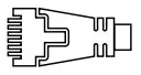
- TP Ethernet interfaces
Use the Ethernet cable to connect one of the interfaces ETH1 (PoE) or ETH2 to other network components.
Alternatively, you can connect the ETH1 (PoE) interface to a PoE injector’s ‘Power Out’ connector.
- Reset button
Pressed up to 5 seconds: device restart
Pressed until first flashing up of all LEDs: configuration reset and device restart
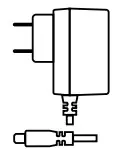
- Power supply connector
Use only the supplied power adapter!


Before initial startup, please make sure to take notice of the information regarding the intended use in the enclosed installation guide!
Operate the device only with a professionally installed power supply at a nearby power socket that is freely accessible at all times.
Antennas are only to be attached or exchanged when the device is switched off. Mounting or demounting antennas while the device is switched on may cause the destruction of the radio module!![]() Please observe the following when setting up the device
Please observe the following when setting up the device
→ The power plug of the device must be freely accessible.
→ To prevent the device from overvoltage damage, an overvoltage-protected power supply is strongly recommended.
→ Do not rest any objects on top of the device
→ Keep all ventilation slots of the device clear of obstruction
→ Please note that support service for third-party accessories is excluded.
LED description & technical details
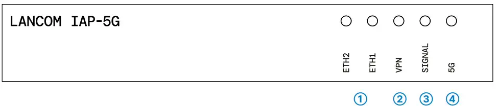
- ETH2, ETH1
Off No networking device attached Green, permanently Connection to network device operational, no data traffic Green, flickering Data traffic - VPN
Off VPN connection not active Green, permanently VPN connection active Green, blinking VPN connection establishment - SIGNAL
Off No cellular reception Green, permanently Good signal strength, greater than or equal to -70 dB Orange, permanently Medium signal strength, field strength between -86 and -71 dB Orange, blinking Low signal strength, field strength less than -87 dB - 5G
Off Cellular interface disabled Green, permanently Connection to cellular network active Green, flickering Cellular data transfer Orange, permanently Logon to cellular network successful Orange, blinking Logging on to cellular network Red, permanently Hardware error/module unavailable Red / green, blinking SIM card error (PIN) Red / orange, blinking Uploading module firmware
Hardware
| Power supply | 12 V DC, external power adapter; via Power-over-Ethernet compliant to IEEE 802.3af |
| Power consumption | Max. 12 W via 12 V power supply, Max. 12 W via PoE |
| Environment | Temperature range -20 to +50 °C; humidity 0-95 %, non-condensing |
| Housing | Robust metal housing, IP 50 protection class, for wall, mast and top-hat rail mounting, 210 mm x 152 mm x 33 mm (L x W x D), weight approx. 1.1 kg (without mounting materials) |
Interfaces
| ETH1 | 10 / 100 / 1000 Mbps auto-sensing, PoE as per IEEE 802.3at |
| ETH2 | 10 / 100 / 1000 Mbps, autosensing |
| External antenna connectors | 4 SMA connectors |
| Config (Com) | USB-C configuration interface |
Package content
| Cable | Ethernet cable, 3 m (not included with bulk items) |
| Antennas | 4 5G / 4G antennas for 5G / LTE |
| Power adapter (Not included withbulk item) | External power adapter (not for WW devices) |
LANCOM, LANCOM Systems, LCOS, LANcommunity and Hyper Integration are registered trademarks. All other names or descriptions used may be trademarks or registered trademarks of their owners. This document contains statements relating to future products and their attributes. LANCOM Systems reserves the right to change these without notice. No liability for technical errors and / or omissions. 0123
*) The additional power LED statuses are displayed in 5-seconds rotation if the device is configured to be managed by the LANCOM Management Cloud.
This product contains separate open-source software components which are subject to their own licenses, in particular the General Public License (GPL). The license information for the device firmware (LCOS) is available on the device‘s WEBconfig interface under “Extras > License information“. If the respective license demands, the source files for the corresponding software components will be made available on a download server upon request.
![]() Hereby, LANCOM Systems GmbH
Hereby, LANCOM Systems GmbH
Adenauerstrasse 20/B2
D-52146 Wuerselen, declares that this device is in compliance with Directives
2014/30/EU, 2014/53/EU, 2014/35/EU, 2011/65/EU, and Regulation (EC) No. 1907/2006.
The full text of the EU Declaration of Conformity is available at the following Internet address:
www.lancom-systems.com/doc


