![]() Hardware Quick Reference
Hardware Quick Reference
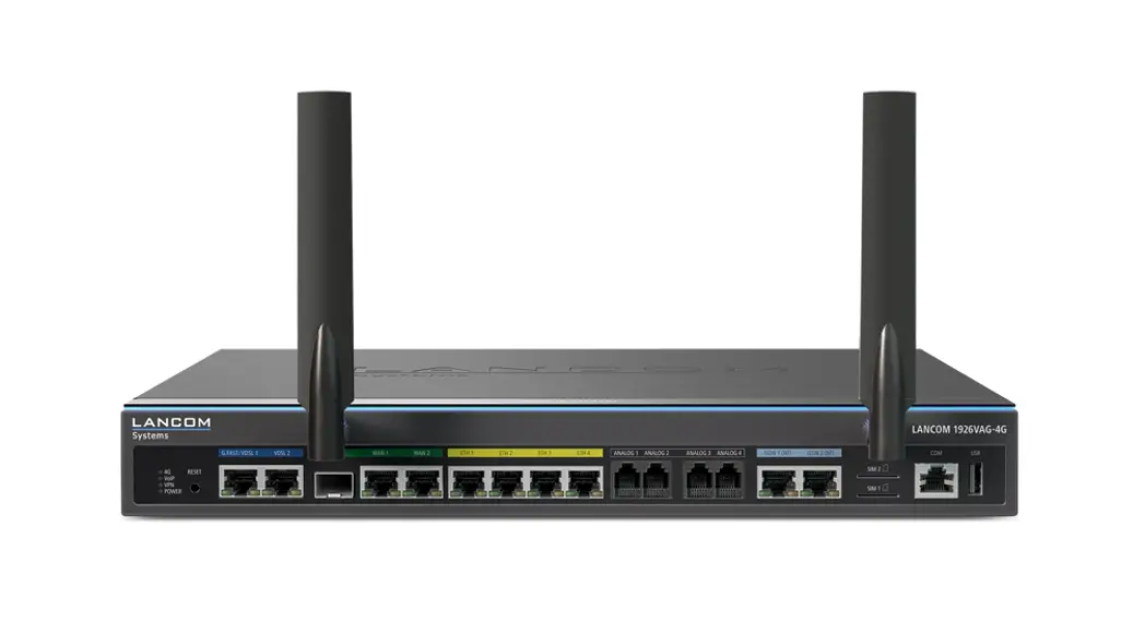
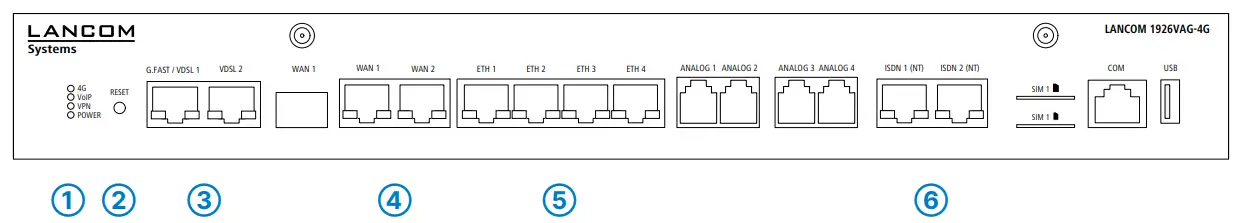
LANCOM 1926VAG-4G
![]()
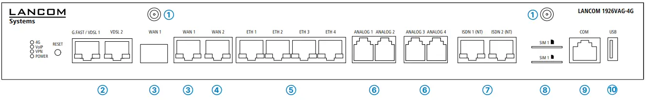
Mounting & connecting
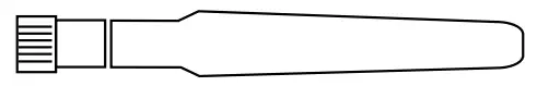
- 4G / LTE antenna connectors
Connect the supplied cellular antennas to the connectors at the front of the device.
- G.FAST / VDSL / ADSL interfaces*
If required, use the supplied DSL cables for the IP-based line to connect each G.FAST / VDSL / ADSL interface to a separate provider’s telephone socket. For more information, please contact your Internet service provider. * Please use the appropriate cables depending on the design
 - WAN 1 interfaces (SFP / TP combo port)
Insert a suitable SFP module (e.g. 1000Base-SX or 1000Base-LX) into the SFP port. Choose a cable compatible with the SFP module and connect it as described in the
module’s documentation. SFP module and cable are not included. If desired, alternatively connect the WAN 1 TP interface to a WAN modem using an ethernet cable.
- WAN 2 interface (TP)
Connect the WAN 2 interface to a WAN modem using an Ethernet cable.
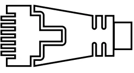
- Ethernet interface
Use the cable with the kiwi-colored connectors to connect one of the interfaces ETH 1 to ETH 4 to your PC or a LAN switch. - Analog interfaces
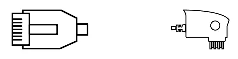
Connect analog terminal devices to the analog interfaces either directly via RJ11 or with the help of the enclosed TAE adapters.
- ISDN interfaces
ISDN 1: Internal (NT) ISDN bus
ISDN 2: Internal (NT) ISDN-bus A 100-Ohm resistor for line termination is switchable in LCOS.
 - SIM card slots
Slide the SIM card(s) into slot SIM1 or SIM2 using the marker to ensure that the card is the right way round. Ensure that the SIM card clicks into place on insertion.
To remove the card from the device, press the card lightly into the device.
Let go to release the SIM card from the slot.
- Configuration interface
Use the included serial configuration cable to connect the serial interface (COM) to the serial interface of the device you want to use for configuring / monitoring.
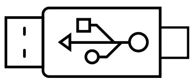
- USB interface
You can use the USB interface to connect a USB printer or a USB storage device.
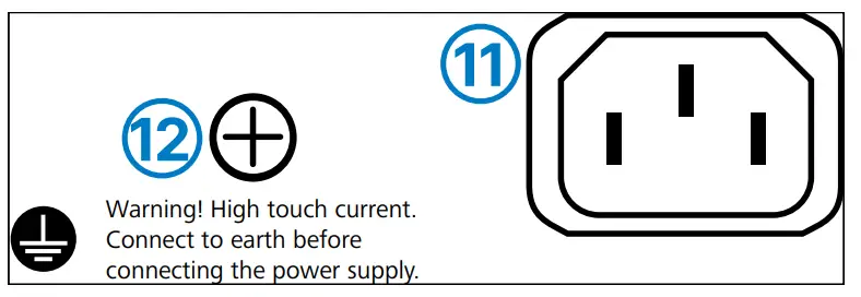
- The power connector and grounding point (device back side)
Supply power to the device via the power connector.
Please use the IEC power cable supplied (separately available for WW devices).
- ATTENTION:
High touch current possible! Connect to earth before connecting the power supply.
 * Please use the appropriate cables depending on the design
 A 100-Ohm resistor for line termination is switchable in LCOS.

Before initial startup, please make sure to take notice of the information regarding the intended use in the enclosed installation guide!
Operate the device only with a professionally installed power supply at a nearby power socket that is freely accessible at all times.![]() Please observe the following when setting up the device
Please observe the following when setting up the device
→The power plug of the device must be freely accessible.
→ For devices to be operated on the desktop, please attach the adhesive rubber footpads
→Do not rest any objects on top of the device
→Keep all ventilation slots on the side of the device clear of obstruction
→Mount the device into a 19” unit in a server cabinet using the provided screws and mounting brackets. Pay attention to the “R” and “L” marks on the brackets for accurate mounting.
→Please note that support service for third-party accessories is excluded.
LED description & technical details
➀ 4G / VoIP / VPN / POWER
4G
| Off | Cellular interface disabled |
| Green, permanently | Connection to cellular network active |
| Green, flickering | Cellular data transmission |
| Orange, permanently | Login to cellular network successful |
| Orange, blinking | Logging on to the cellular network |
| Red, permanently | Hardware error/module unavailable |
| Red / green, blinking | SIM card error (PIN) |
| Red/orange, blinking | Uploading module firmware |
VoIP
| Off | No SIP accounts are defined or VCM is off |
| Green, permanently | All defined and active SIP accounts (outgoing) were successfully registered |
| Red, permanently | Not all of the defined and active SIP accounts were registered (possibly still in process) |
| Red or green, inverseflashing | Number of currently used lines (connecting or connected) |
VPN
| Off | VPN connection inactive |
| Green, permanently | VPN connection active |
| Green, flashing | VPN connecting |
POWER
| Off | Device switched off |
| Green, permanently* | Device operational, resp. device paired/claimed and LANCOM Management Cloud (LMC) accessible |
| Green / red, blinking | No password set. Without a password the configuration data in the device is unprotected. |
| Red, blinking | Charge or time limit reached |
| 1x green inverse blinking* | Connection to the LMC active, pairing OK, device not claimed |
| 2x green inverse blinking* | Pairing error, resp. LMC activation code not available |
| 3x green inverse blinking* | LMC not accessible, resp. communication error |
➁ RESET
| Reset button | Short press > restart the device Long press > reset the device |
➂ G.FAST / VDSL 1 / VDSL 2
| Off | Interface deactivated |
| Green, blinking | DSL connecting |
| Green, permanently | DSL connection active |
| Green, flickering | DSL data transmission |
| Green / orange, flickering | DSL transmission error |
| Green/orange, blinking synchronously | DSL hardware error |
| Orange, blinking | DSL training |
| Orange, permanently | DSL sync |
➃ WAN 1 / WAN 2
| Green, orange off | No networking device connected |
| Green, permanently | Connection to the network device operational, no data traffic |
| Green, flickering | Data transmission |
| Orange off | 1000 Mbps |
| Orange, permanently | 10 / 100 Mbps |
➄ ETH 1 – ETH 4
| Green, orange off | No networking device connected |
| Green, permanently | Connection to the network device operational, no data traffic |
| Green, flickering | Data transmission |
| Orange off | 1000 Mbps |
| Orange, permanently | 10 / 100 Mbps |
➅ ISDN 1 (NT) / ISDN 2 (NT)
| Off | Interface deactivated |
| Green, permanently | D-channel active |
| Green, blinking | ISDN connection active |
| Orange, blinking | ISDN connecting |
| Green/orange, blinking synchronously | ISDN hardware error |
| Orange, permanently | Connection inactive |
Hardware
| Power supply | Internal power supply unit (100–240 V, 50-60 Hz) |
| Power consumption | Max. 36 W |
| Environment | Temperature range 0–40 °C, humidity 0–95 %; non-condensing |
| Housing | Robust metal housing, 1 HU with mounting brackets for 19“ installation, W 345 x H 44 x D 253 mm) |
| Number of fans | 1 quiet fan |
Interfaces
| G.FAST/VDSL1/ VDSL 2 | G.FAST according to ITU G.9700 and G.9701, profiles 106a, 212a VDSL2 according to ITU G.993.2, profiles 8a, 8b, 8c, 8d, 12a, 12b, 17a, 35b VDSL super vectoring according to ITU G.993.2 (Annex Q) VDSL2 vectoring: according to ITU G.993.5 (G.Vector) Compatible with VDSL2 from Deutsche Telekom Compatible with the U-R2 connection of Deutsche Telekom (1TR112) ADSL2+ over ISDN according to ITU G.992.5 Annex B/J with DPBO, ITU G.992.3, and ITU G.992.1 ADSL2+ over POTS according to ITU G.992.5 Annex A/M with DPBO, ITU G.992.3, and ITU G.992.1 Supports only one virtual connection in ATM (VPI-VCI pair) at a time Automatic detection of Deutsche Telekom VDSL connections with VLAN ID 7 |
| WAN 1 / WAN 2 | WAN 1 SFP: Compatible with optional LANCOM SFP modules. Set as a WAN port ex-factory, can be configured as a LAN port. WAN 1 / WAN 2 TP: 10 / 100 / 1000 Base-TX, autosensing full duplex (WAN 1) / autosensing (WAN 2), auto node hub |
| ETH1 – ETH 4 | 4 individual ports, 10 / 100 / 1000 Mbps Gigabit Ethernet, by default set to switch mode. Up to 3 ports can be operated as additional WAN ports. Ethernet ports can be electrically disabled in the LCOS configuration. |
| Analog 1 – Analog 4 | Use the cables of your analog devices to connect them with the analog interfaces. If necessary, use the enclosed adapters |
| ISDN 1 / ISDN 2 | ISDN 1: Internal (NT) ISDN bus. Connect the ISDN interface to an ISDN cable and the ISDN device.ISDN 2: Internal (NT) ISDN bus. Connect the ISDN interface to an ISDN cable and the ISDN device. |
| Config (Com) / V.24 | Serial configuration interface / COM-port: 9,600 – 115,200 baud |
| USB | USB 2.0 hi-speed host port for connecting USB printers (USB print server), serial devices (COMport server) or USB drives (FAT file system) |
| 4G | Two SMA connectors for the supplied dipole rod antennas (LTE, UMTS), compatible LANCOM AirLancer antennas for 4G, or from other manufacturers. Please respect the restrictions which apply in your country when setting up an antenna system (particularly antenna gain/transmission power). |
Data transmission in cellular networks
| Supported standards | UMTS, HSxPA, HSPA+, LTE, LTE Advanced |
| Supported cellular network bands | Band 1 (2100 MHz), Band 3 (1800 MHz), Band 7 (2600 MHz), Band 8 (900 MHz), Band 20 (800 MHz), Band 28 (700 MHz), Band 32 (1500 MHz), Band 38 (2600 MHz), Band 40 (2300 MHz), Band 41 (2500 MHz), Band 42 (2500 MHz), Band 43 (2500 MHz) |
| Max. transmission power | +23 dBm |
Package content
| Cables | 2 DSL cables for IP-based connection, 4.25 m, or 2 DSL cables, 3 m (dark blue connectors), depending on the version; 1 Ethernet cable, 3 m (kiwi colored connectors); 1 IEC power cord 230 V (not for WW devices) |
| Antennas | Two LTE / 4G antennas for LTE / UMTS |
| Adapters | 4 TAE adapters (RJ11 – TAE) |
| Mounting brackets | Two 19” brackets for rack mounting |
*) The additional power LED statuses are displayed in a 5-second rotation if the device is configured to be managed by the LANCOM Management Cloud.
This product contains separate open-source software components which are subject to their own licenses, in particular the General Public License (GPL). The license information for the device firmware (LCOS) is available on the device‘s WEBconfig interface under “Extras > License information“.
If the respective license demands, the source files for the corresponding software components will be made available on a download server upon request.
Hereby, LANCOM Systems GmbH | Adenauerstrasse 20/B2 | D-52146 Wuerselen, declares that this device is in compliance with Directives 2014/30/EU, 2014/53/EU, 2014/35/EU, 2011/65/EU, and Regulation (EC) No. 1907/2006. The full text of the EU Declaration of Conformity is available at the following Internet address:
www.lancom-systems.com/doc
LANCOM, LANCOM Systems, LCOS, LAN community and Hyper Integration are registered trademarks. All other names or descriptions used may be trademarks or registered trademarks of their owners.
This document contains statements relating to future products and their attributes. LANCOM Systems reserves the right to change these without notice. No liability for technical errors and/or omissions..


