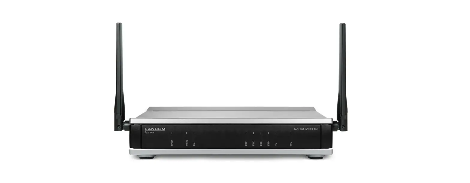
LANCOM 1790VA-4G Router User Guide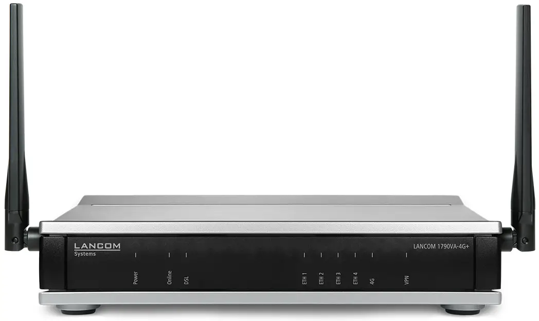
Product Overview
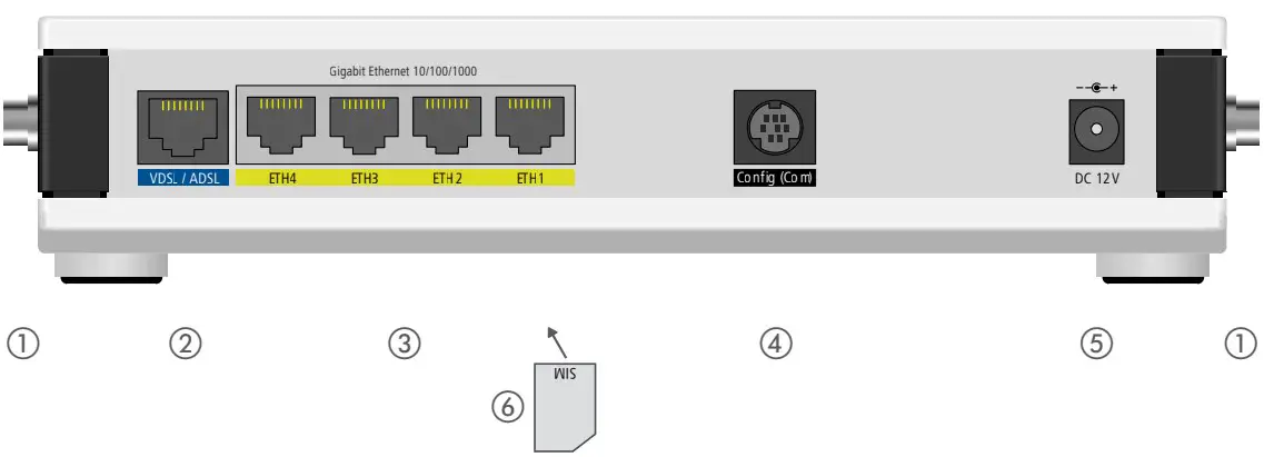
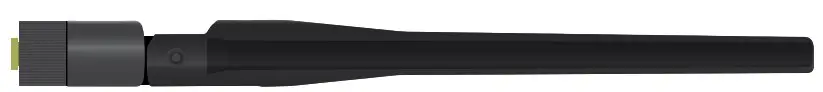
- LTE / 4G antennas
Connect the two supplied cellular antennas to the connectors at the side of the device.
- VDSL / ADSL interface
Use the supplied DSLcable for the IP-based line to connect the VDSL interface and the provider’s telephone socket. For more information, please contact your Internet service provider.
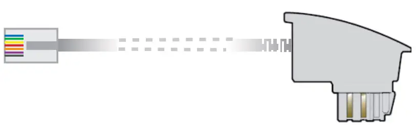
- Ethernet interfaces
Use the cable with the kiwi-colored connectors to connect one of the interfaces ETH 1 to ETH 4 to your PC or a LAN switch.
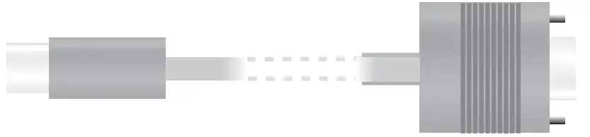
- Configuration interface
Use a serial configuration cable to connect the serial interface (COM) to the serial interface of the device you want to use for configuring / monitoring (separately available).
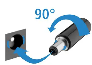
- Power
After connecting the cable to the device, turn the bayonet connector 90° clockwise until it clicks into place. Use only the supplied power adapter.
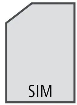
- SIM card slot (bottom side of the device)
Release the SIM-card holder and lever it upwards. Slide the SIM card into the guide slot of the SIM-card holder. Press the holder down until it clicks into place.

![]() Please observe the following when setting up the device.
Please observe the following when setting up the device.
- Do not rest any objects on top of the device
- For devices to be operated on the desktop, please attach the adhesive rubber footpads
- In case of wall mounting, use the drilling template as supplied
Before initial startup, please make sure to take notice of the information regarding the intended use in the enclosed installation guide! Operate the device only with a professionally installed power supply at a nearby power socket that is freely accessible at all times.
MOUNTING AND CONNECTING THE DEVICE
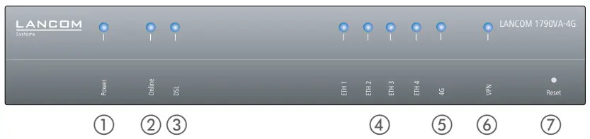
Power
| Off | Device switched off |
| Green, permanently* | Device operational, resp. device paired / claimed and LANCOM Management Cloud (LMC) accessible |
| Red / green blinking | Configuration password not set. Without a configuration password, the configuration data in the device is unprotected. |
| Red blinking | Charge or time limit reached |
| 1x green inverse blinking* | Connection to the LMC active, pairing OK, device not claimed |
| 2x green inverse blinking* | Pairing error, resp. LMC activation code not available |
| 3x green inverse blinking* | LMC not accessible, resp. communication error |
Online
| Off | WAN connection inactive |
| Green, blinking | WAN connection is established (e.g. PPP negotiation) |
| Green, permanently | WAN connection active |
| Red, permanently | WAN connection error |
DSL
| Off | Interface deactivated |
| Green, permanently | DSL connection active |
| Green, flickering | DSL data transfer |
| Red, flickering | DSL transfer error |
| Red / orange, blinking | DSL hardware error |
| Orange, blinking | DSL training |
| Orange, permanently | DSL sync |
ETH
| Off | No networking device attached |
| Green, permanently | Connection to network device operational, no data traffic |
| Green, flickering | Data transmission |
4G
| Off | Cellular interface disabled |
| Green, permanently | Connection to cellular network active |
| Green, flickering | Cellular data transfer |
| Orange, permanently | Logon to cellular network successful |
| Orange, blinking | Logging on to cellular network |
| Red, permanently | Hardware error/module unavailable |
| Red / green, blinking | SIM card error (PIN) |
| Red / orange, blinking | Uploading module firmware |
VPN
| Off | VPN connection inactive |
| Green, permanently | VPN connection active |
| Green, flashing | VPN connecting |
Reset
| Reset button | Operated e.g. with a paper clip a short press: Restart the device a long press: Reset the device |
Hardware
| Power supply | 12 V DC, external power adapter (230 V); bayonet connector to secure against disconnection |
| Power consumption | Max. ca. 18 W |
| Environment | Temperature range 0–40 °C; humidity 0–95 %; non-condensing |
| Housing | Robust synthetic housing, rear connectors, ready for wall mounting, Kensington lock; mea- sures 210 x 45 x 140 mm (W x H x D) |
| Number of fans | 1 quiet fan |
Interfaces
| WAN: VDSL2 | a VDSL2 as per ITU G.993.2; profiles 8a, 8b, 8c, 8d, 12a, 12b, 17a, 35b a VDSL Supervectoring as per ITU G.993.2 (Annex Q) a VDSL2 vectoring as per ITU G.993.5 (G.Vector) a Compatible to VDSL2 from Deutsche Telekom a Compatible to U-R2 from Deutsche Telekom (1TR112) a ADSL2+ over ISDN as per ITU G.992.5 Annex B/J with DPBO, ITU G.992.3, and ITU G.992.1 a ADSL2+ over POTS as per ITU G.992.5 Annex A/M with DPBO, ITU G.992.3, and ITU.G.992.1 a Supports just one virtual connection at a time in ATM (VPI-VCI pair) |
| ETH | 4 individual ports, 10 / 100 / 1000 Mbps Gigabit Ethernet, by default set to switch mode. Up to 3 ports can be operated as additional WAN ports. Ethernet ports can be electrically disabled in the LCOS configuration. |
| 4G: Ant 1, Ant 2 | Two SMA connectors for the supplied dipole rod antennas (LTE, UMTS), compatible LANCOM AirLancer antennas for 4G or 3G, or from other manufacturers. Please respect the restrictions which apply in your country when setting up an antenna system (in particular the antenna gain and transmission Power). |
| Config (Com) / V.24 | Serial configuration interface/COM-port (8-pin mini-DIN): 9,600 – 115,200 baud, suitable for optional connection of analog/GPRS modems. Supports internal COM-port server and provides transparent asynchronous serial-data transfer via TCP. |
WAN protocols
VDSL, ADSL, Ethernet: PPPoE, PPPoA, IPoA, Multi-PPPoE, ML PPP, PPTP (PAC or PNS) and IPoE (with or without DHCP), RIP-1, RIP-2, VLAN
Declaration of Conformity
Hereby, LANCOM Systems GmbH | Adenauerstrasse 20/B2 | D 52146 Wuerselen, declares that this device is in compliance with Directives 2014/30/EU, 2014/53/EU, 2014/35/EU, 2011/65/EU, and Regulation (EC) No. 1907/2006.
The full text of the EU Declaration of Conformity is available at the following Internet address: www.lancom-systems.com/doc
Package content
| Manual | Quick Reference Guide (DE/EN); Installation Guide (DE/EN) |
| Cable | 1 Ethernet cable, 3 m (kiwi colored connectors); 1 DSL cable for an IP-based line, 4.25 m |
| Antennas | 2 LTE / 4G antennas |
This product contains separate open-source software components which are subject to their own licenses, in particular the General Public License (GPL). The license information for the device firmware (LCOS) is available on the device‘s WEBconfig interface under “Extras > License information“. If the respective license demands, the source files for the corresponding software components will be made available on a download server upon request.
![]()


