![]() SYSTEMS IAP-1781VAW Plus Routers and SD-WAN Edge
SYSTEMS IAP-1781VAW Plus Routers and SD-WAN Edge
User Guide

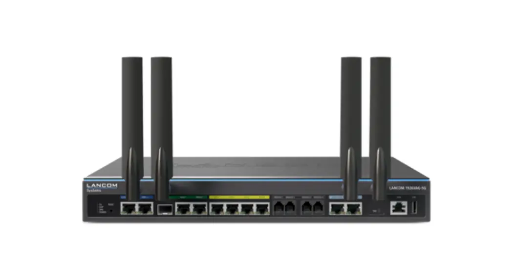
IAP-1781VAW Plus Routers and SD-WAN Edge
 Please observe the following when setting up the device
Do not rest any objects on top of the device
CAUTION! – Device surface may be hot during operation
This device complies with the regulations for devices of protection class 2 with functional ground
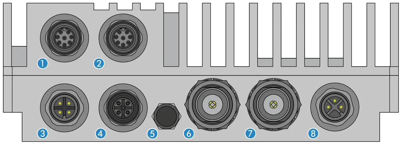
- Ethernet interface
- Connect the interfaces a (ETH 1) or b (ETH 2) with the included network cable to your PC or a LAN switch.

- VDSL- / ADSL interface Use the supplied DSL cable for the IP-based line to connect the VDSL interface and the provider’s telephone socket. (For more information, please contact your Internet service provider.)

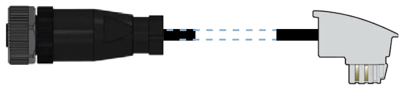
- ISDN interface
Connect the internal (NT) ISDN bus with the included cable to an ISDN phone or an ISDN phone system.
- Membrane seal
Only to be opened by a service technician - Wi-Fi antennas
- Connect the Wi-Fi antennas (not included) to the N connectors f Ant 1 and g Ant 2.
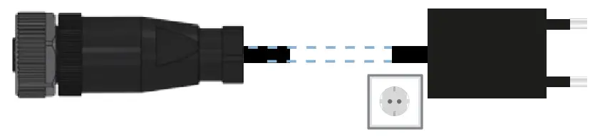
Depending on how the antennas are to be used, ‘Antenna Grouping’ may need to be configured in order to provide the desired MIMO behavior. - Power
Supply power to the device via the power connector.


 The device is designed for protection category IP54 and thus protected all-around against splash water and dust in harmful quantity.
The device has to be installed in sufficiently protected environment, so that no direct weathering can occur.
When working with separately purchased antennas, please ensure you do not exceed the maximum permissible transmission power. The system operator is responsible for adhering to the threshold values.
Antennas are only to be attached or changed when the device is switched off. Mounting or demounting antennas with the device switched on may cause the destruction of the Wi-Fi module!
Before initial startup, please make sure to take notice of the information regarding the intended use in the enclosed installation guide!
Operate the device only with a professionally installed power supply at a nearby power socket that is freely accessible at all times.
TECHNICAL DATA
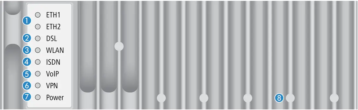
ETH1 / ETH2
| Off | No network device connected |
| Green, permanently | Network device connected, no data traffic |
| Green, flickering | Data transmission |
DSL
| Off | Interface disabled |
| Green, permanently | DSL connection active |
| Green, flickering | DSL data transmission |
| Red, flickering | DSL transmission error |
| Red / orange, blinking | DSL hardware error |
WLAN
| Off | No Wi-Fi network defined or Wi-Fi module deactivated. The Wi-Fi module is not transmitting beacons. |
| Green, permanently | At least one Wi-Fi network is defined and Wi-Fi module activated. The Wi-Fi module is transmitting beacons. |
| Green, inverse flashing | Number of flashes = number of connected Wi-Fi stations and P2P wireless connections, followed by a pause (default). Alternatively the frequency of the flashing can indicate signal strength over the defined P2P link or the signal strength between the access point and the device operating in client mode. |
| Green, blinking | DFS scanning or other scan procedure |
ISDN
| Off | Interface disabled |
| Green, permanently | D-channel active |
| Orange, permanently | B-channel active |
| Green, blinking | ISDN connection active |
| Orange, blinking | ISDN connection establishment |
| Red / orange, blinking | ISDN hardware error |
VoIP
| Off | No SIP accounts defined or VCM disabled |
| Green, permanently | All defined and active SIP accounts (outgoing) have been successfully registered |
| Red, permanently | Not all defined and active SIP accounts have been registered (possibly still in process) |
| Red or green, inversely flashing | Number of currently used lines (connecting or connected) |
VPN
| Off | VPN connection not active |
| Green, permanently | VPN connection active |
| Green, flashing | VPN connection establishment |
Power
| Off | Device switched off |
| Green, permanently* | Device operational, resp. device paired / claimed and LANCOM Management Cloud (LMC) accessible |
| Green / orange, blinking | Configuration password not set. Without a configuration password, the configuration data in the device is unprotected. |
| Red, blinking | Charge or time limit reached |
| 1x green inverse blinking* | Connection to the LMC active, pairing OK, device not claimed |
| 2x green inverse blinking* | Pairing error, resp. LMC activation code not available |
| 3x green inverse blinking* | LMC not accessible, resp. communication error |
Reset
| Reset area | Operation via the enclosed magnet unit. The imprint shows the correct insertion position between the cooling ribs. short insertion: device restart long insertion: device reset |
Hardware
| Power supply | Internal power supply (100-240 V, 50-60 Hz) |
| Power consumption | Max. ca. 14 W |
| Environment | Temperature range -25–70 °C, humidity 0–95 %, non-condensing |
| Housing | Robust metal housing, protection class IP 54, dimensions 250x158x55 mm (HxWxD) |
| Number of fans | None; fanless design, no rotating parts, high MTBF |
Interfaces
| WAN: VDSL2 | A VDSL2 as per ITU G.993.2; profiles 8a, 8b, 8c, 8d, 12a, 12b, 17a A Compatible to VDSL2 from Deutsche Telekom AG (only over ISDN) A ADSL conformity according to: ADSL2+ over ISDN as per ITU G.992.5 Annex B /J with DPBO (POTS: Annex A/Annex M), ADSL2 over ISDN as per ITU G.992.3 Annex B (POTS: Annex A/L), ADSL over ISDN as per ITU G.992.1 Annex B (POTS: Annex A) A Supports just one virtual connection at a time in ATM (VPI-VCI pair) |
| ETH | 2 individual ports, 10 / 100 / 1000 Mbps Gigabit Ethernet, by default set to switch mode. 1 port can be operated as additional WAN ports. Ethernet ports can be electrically disabled in the LCOS configuration. |
| ISDN | Internal (NT) ISDN S0 bus |
| Ant 1, Ant 2 | Two NJ connectors for external LANCOM AirLancer antennas or for antennas from other vendors. Please respect the restrictions which apply in your country when setting up an antenna system. |
WAN protocols
| VDSL, ADSL, Ethernet | PPPoE, PPPoA, IPoA, Multi-PPPoE, ML-PPP, PPTP (PAC or PNS) and IPoE (with or without DHCP), RIP-1, RIP-2, VLAN, GRE, EoGRE, L2TPv2 (LAC or LNS), IPv6 over PPP (IPv6 and IPv4/IPv6 dual stack session), IP(v6)oE (autoconfiguration, DHCPv6 or static) |
| ISDN | 1TR6, DSS1 (Euro-ISDN), PPP, X75, HDLC, ML-PPP, V.110/GSM/HSCSD |
Declaration of Conformity
Hereby, LANCOM Systems GmbH | Adenauerstrasse 20/B2 | D-52146 Wuerselen, declares that this device is in compliance with Directives 2014/30/EU, 2014/53/EU, 2014/35/EU, 2011/65/EU, and Regulation (EC) No. 1907/2006. The full text of the EU Declaration of Conformity is available at the following Internet address: www.lancom-systems.com/doc
Package contents
| Documentation | Quick Reference Guide (DE/EN), Installation Guide (DE/EN) |
| Cables | 2 Ethernet cables 3m; 1 DSL cable 3 m; 1 ISDN cable 2m; 1 power cord 3m |
| Accessories | 1 wall mount kit, 1 reset magnet |
This product contains separate open-source software components which are subject to their own licenses, in particular the General Public License (GPL). The license information for the device firmware (LCOS) is available on the device‘s WEBconfig interface under “Extras > License information“. If the respective license demands, the source files for the corresponding software components will be made available on a download server upon request.
*) The additional power LED statuses are displayed in 5-seconds rotation if the device is configured to be managed by the LANCOM Management Cloud.
LANCOM, LANCOM Systems, LCOS, LANcommunity and Hyper Integration are registered trademarks. All other names or descriptions used may be trademarks or registered trademarks of their owners. This document contains statements relating to future products and their attributes. LANCOM Systems reserves the right to change these without notice.
No liability for technical errors and / or omissions.
111858/07/21


