
CISA 59751 Efast Panic Exit Devices

“eFAST TOUCH MORTICE” SERIES PANIC EXIT DEVICE – Installer’s instruction sheet Item 59751 – To be installed with a panic function mortice lock.
- Limit values prescribed by the UNI EN 1125 standard with extension. This product is certified for use on standard and/or fire doors.


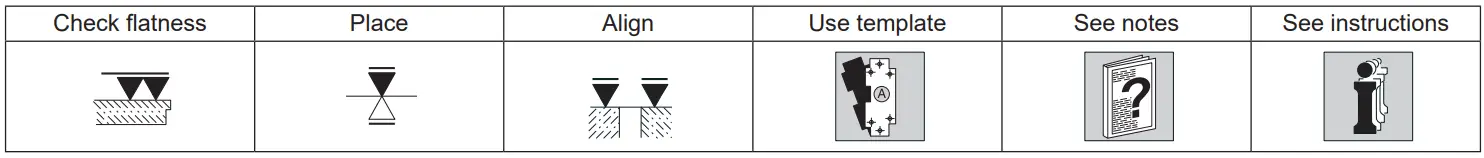
SYMBOLS
- Right-handed door (R).
- Left-handed door (L).
- Single leaf door (1).
- Double leaf door (2).
- Use of outside access devices (OD).
- Optional part supplied on request (OPT).


| Ref. | Q.ty | COMPONENTS | Ref. | Q.ty | COMPONENTS |
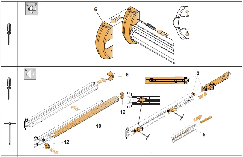
| 1 | 1 | Main case | 8 | 1 | Spindle |
| 2 | 1 | Rear support | 9 | 1 | Secondary cover |
| 3 | 1 | Front bracket | 10 | 1 | Bar |
| 4 | 1 | Rear bracket | 11 | 1 | Rear bar plug |
| 5 | 1 | Connecting rod | 12 | 1 | Front bar plug |
| 6 | 1 | Main cover | 13 | 1 | Plate |
| 7 | 2 | Main cover plug | 14 | 1 | Connecting cable |
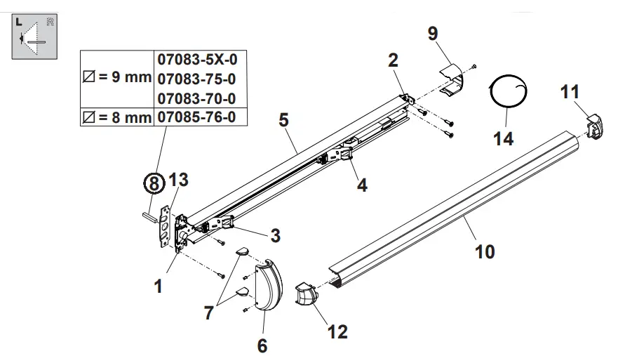
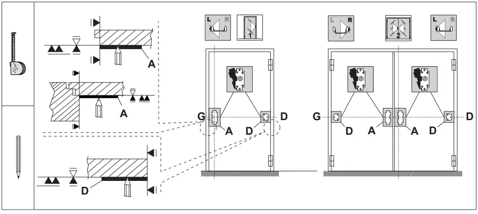
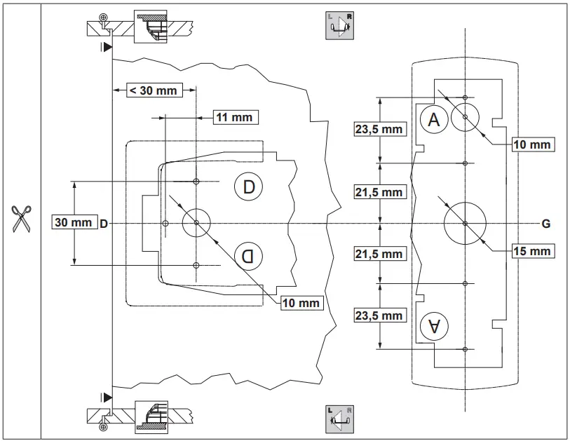
| Ref. | Templates used to position: |
| A | Main case |
| D | Rear support |
| The templates must be cut out and are included in the instruction sheet on page 11. |
Small hardware items used
Type of installation on blind doors (C) with tubular frame/glazed doors (T) and wooden doors (L)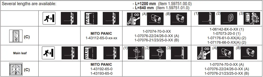
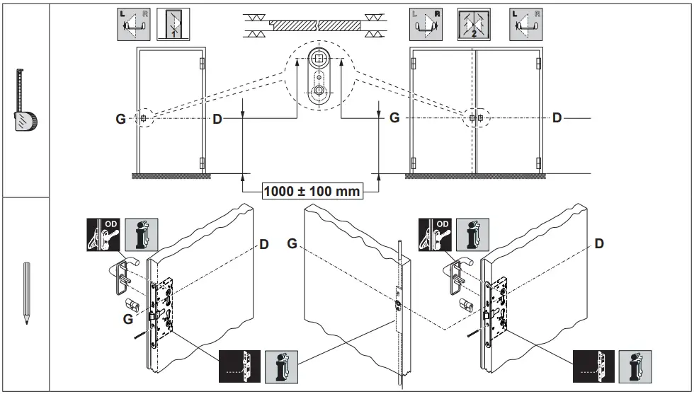
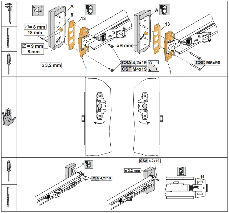
PANIC FUNCTION LOCK INSTALLATION
PANIC EXIT DEVICE LENGTH CHECKING
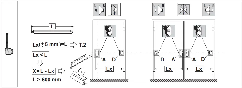
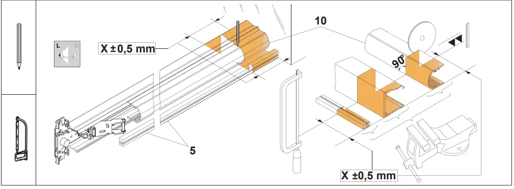
PANIC EXIT DEVICE LENGTH ADJUSTMENT
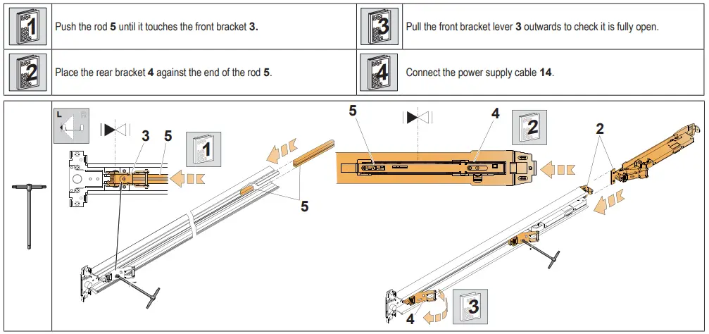
PANIC EXIT DEVICE INSTALLATION
WIRING
| MOTOR CHARACTERISTICS | ||
| Power supply voltage | 12 | |
| Absorbed current (max) | 1.5A @ 12V | |
| Degree of protection | IP X0 | |
| Operating temperature | -10 ÷ +55°C | |
| Certifications See “Regulatory Addendum” | ||
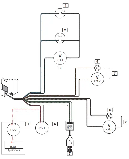
| 1 | Hold open switch (optional) | |
| 2 | Remote opening button | |
| 3 | Ext V 1 = 12V , min I = 1 mA | |
| 4 | Lock closed LED (optional) ext V 2 = 12V , max I = 0.5 A | |
| 5 | Int V = 12V , I = 2 A | |
| 6 | Lock open LED (optional) ext V 3 = 12V , max I = 0.5 A | |
| 7 | Programming cable Item 1.07030.41.0 (optional) | |
| 8 | This configuration is an alternative to 5 Power supply with battery charger (UPS function) Class B 12V , I=2A. Buffer battery 12V, 0.8Ah Recommended when installing device on fire doors | |
| WARNING: Do not connect the product directly to the mains 230V ~. CISA declines all responsibility for the compliance of the existing system to current regulations. | ||
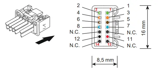
| Pinout | Colour | Signal | Descriptions | Specifications |
| 1 | Green | TX – | Programming cable | – |
| 2 | Green/White | TX + | ||
| 3 | Orange | OUT1 / C | Lock status securely locked | 12 V , max I = 0.5 A |
| 4 | Orange/White | OUT1 / NO | ||
| 5 | Brown | OUT2 / C | Lock status open | 12 V , max I = 0.5 A |
| 6 | Brown/White | OUT2 / NO | ||
| 7 | Blue | IN1+ | Input for opening | 12 V , 12V ~ Min I = 1mA |
| 8 | Blue/White | IN1- | ||
| 9 | – | – | Not connected | – |
| 10 | – | – | Not connected | – |
| 11 | Red | V+ | Power supply | 12 V , I = 1.5 A |
| 12 | Black | V- | ||
| 13 | – | – | Not connected | – |
| 14 | – | – | Not connected | – |
| The cable supplied can be connected with the existing electric system. Check the maximum length of the cables with the table.
WARNING: CISA declines all responsibility for the compliance of the existing system to current regulations. |
(*) The table gives the minimum section of the cables depending on the length of the cable to connect with the cable supplied. |
| WARNING: Use the cable supplied with the lock only.
We recommend using cable guards (see the accessories section) for the power supply cable between the frame and the door. The motor must be powered at all times, even when the door is open. | |
| The power supply is not supplied with the kit. See item 1.07060.10.0 in the accessories section.
WARNING: A power supply with the following characteristics is recommended: Output: 12V – 2A Protection with fuse 2A, 250V Protection: OVP (overvoltage), OCP (overcurrent) Certifications: CE, in compliance with directives 2014/30/EU, 2014/35/EU Class 2 (double insulation), LPS source (in compliance with IEC 62368), SELV, UL Listed or UL Recognized. | |
| OPERATION The panic exit device has the same features as the mechanical version, in compliance with EN1125, with an additional power- assisted opening function thanks to the interaction between the mechanics and the electronics.
INTERFACING FOR OPENING The panic exit device is opened by pressing button 1 or opening switch 2 (see diagram 1).
1. Single opening: when button 1 is pressed, the panic exit device opens for 3 seconds (this time can be set up to 180 sec on the PC), after which it closes and the latchbolts automatically engage.
2. Hold open mode: the panic exit device can be interfaced with a switch 2. When the switch is closed, the panic exit device remains open; it will lock again only when the switch is opened. Cannot be installed on fire doors.
WARNING: The electric current produced by some applications can be high, keeping the lock open even after the opening button has been released. It is advisable to interface the input command with a repeater relay and connect the motor as shown in diagram 3.
WARNING: POWER FAILURE If there is a power failure, the panic exit device will always revert to locked when power is restored. | |
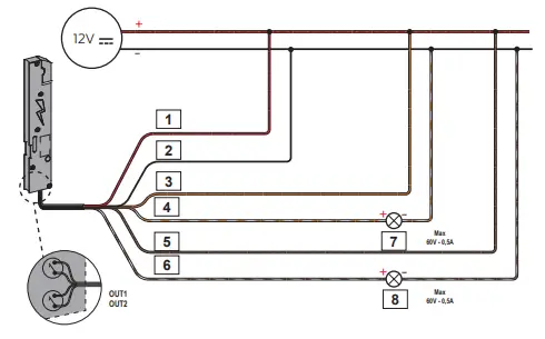
| INTERFACING FOR PANIC EXIT DEVICE STATUS (example of installation with an actuator to open and close the door) OUT1 and OUT2 outputs can be used to remotely control the status of the panic exit device. OUT1 output is activated when the panic exit device is locked (latchbolt and lock engaged). OUT2 output is activated when the panic exit device is completely open (latchbolt and lock withdrawn).
IMPORTANT: Both the outputs are free contacts normally open (C, NO) with a maximum capacity of 60V, 0.5mA
WARNING: Connect devices with a maximum current absorption of 0.5A and a maximum voltage of 60V. CISA declines all responsibility for the compliance of third-party devices used.
It is possible to connect 12V lights (see the accessories) directly to the lock power supply. Respect the polarity (+/-) of the lights/LEDs.
A repeater relay (item 1.07022.20.0) is needed to control locks, electric strike coils or 230V devices. | |
Diagram 1: example of button/switch connection to panic exit device power supply. KEY
| 1 | Red | V+ | Power supply (+) |
| 2 | Black | V- | Power supply (-) |
| 3 | Blue | IN1+ | Input for opening (+) |
| 4 | Blue/white | IN1- | Input for opening (-) |
| 5 | Button |
| 6 | Optional switch for passage mode |
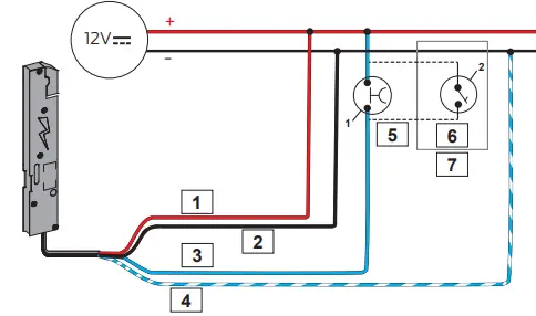
Diagram 2: example of panic exit device connection to an intercom. KEY
| 1 | Red | V+ | Power supply (+) |
| 2 | Black | V- | Power supply (-) |
| 3 | Blue | IN1+ | Input for opening (+) |
| 4 | Blue/white | IN1- | Input for opening (-) |
| 5 | Lock 12V~ |
| 6 | Intercom |
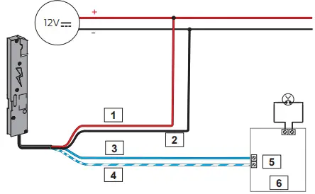
Diagram 3: example of panic exit device connection to an intercom using a repeater relay. KEY
| 1 | Red | V+ | Power supply (+) |
| 2 | Black | V- | Power supply (-) |
| 3 | Blue/white | IN1- | Input for opening (-) |
| 4 | Blue | IN1+ | Input for opening (+) |
| 5 | Lock 12V~ |
| 6 | Intercom |
| 7 | Opening button |
| 8 | Relay |
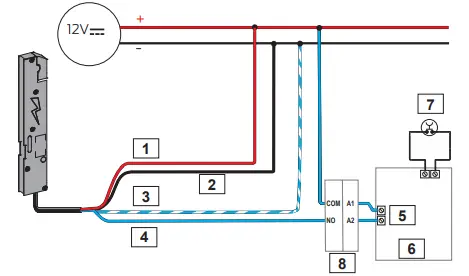
Diagram 4: interfacing for panic exit device status (example of installation with an actuator to open and close the door) KEY
| 1 | Red | V+ | Power supply (+) |
| 2 | Black | V- | Power supply (-) |
| 3 | Orange | OUT1/C | Lock status securely locked |
| 4 | Orange/white | OUT1/NO | Lock status securely locked |
| 5 | Brown | OUT2/C | Lock status open |
| 6 | Brown/white | OUT2/NO | Lock status open |
| 7 | Door status locked |
| 8 | Door status open |
INSTALLATION COMPLETION – FINAL CHECKS
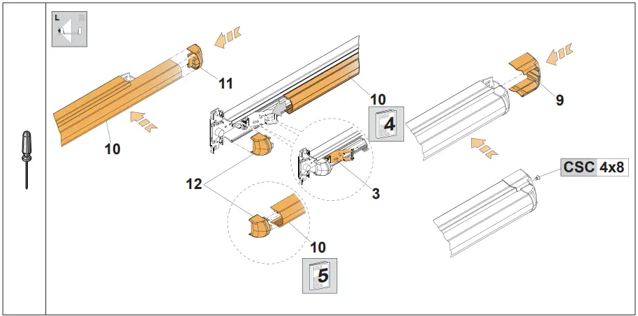
- Insert the front bracket pins 3 in the grooves of the bar 10.
- Insert the front bar plug inserts 12 in the grooves of the bar 10.

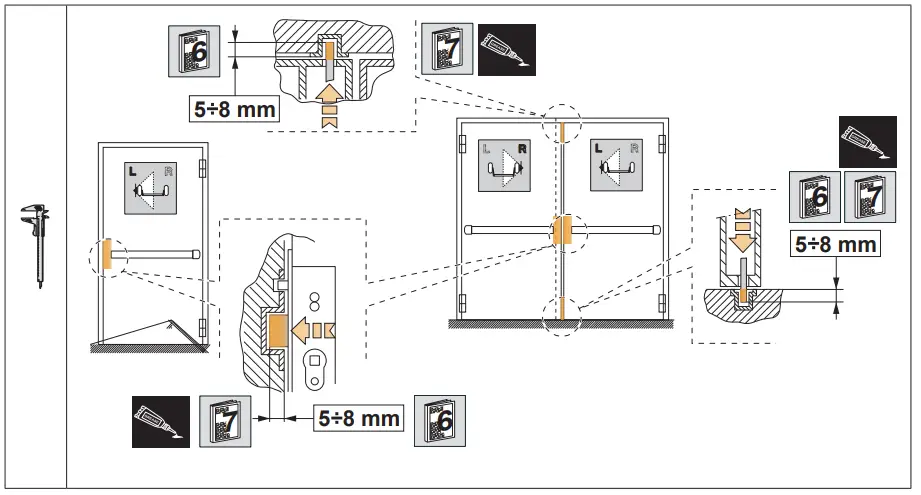
- Check with the door closed: the latchbolt and/or tips of the rods enter the strikers correctly.
- Grease the point where the latchbolt and/or tips of the rods enter the striker.

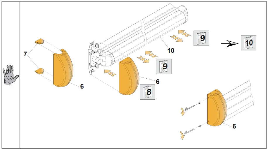
- Press the bar 10 before inserting the cover 6.
Check the bar 10 springs back to its original position after it has been pushed. - During final checking, ensure assembly compliance by measuring the operating strength necessary to work the exit device by using a dynamometer. After installation has been completed, register the installed product codes and measured operating effort on the “Certificate of correct installation”.

ACCESSORY INSTALLATION
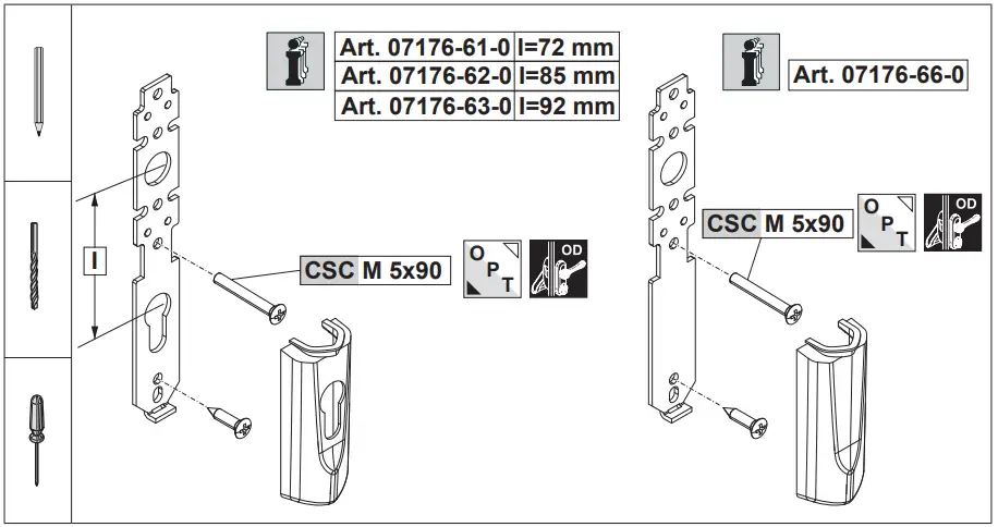
ACCESSORIES
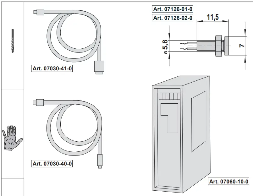
- Item 07126-01-0
Red LED - Item 07126-02-0
Green LED - Item 07030-40-0
Power supply cable (L = 4 m). - Item 07030-41-0
Programming cable
Item 07060-10-0 - Power supply:
- Input: 110÷240V AC 50/60Hz 0.7A
- Output: 12V DC 2.5A Class 2 output
- Certified UL Listed
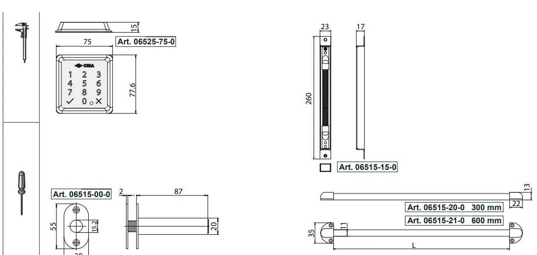
- Item 06525-75-0
Cabled keypad for individual access control by PIN code, for E0000 CISA MOTOR series. Polished black finish. AVAILABLE FINISHES – Satin-finished chrome (fin. B1) - Item 06515-00-0
Concealed cable guard - Item 06515-00-0
Concealed cable guard - Items 06515-20-0 – 06515-21-0
External cable guard with spring
CERTIFICATES OF CONFORMITY
- THIS PRODUCT IS CERTIFIED IN COMPLIANCE WITH FOLLOWING CONSTRUCTION PRODUCTS REGULATION NO. 305/2011.
- Panic exit device with touch bar “eFAST TOUCH MORTICE” series, installed with locks from the MITO PANIC series.
- Classification: B – Designed for use on fire doors.
- Single or double leaf wooden fire door: I120 (ref. EN1634-1)
- Single or double leaf steel fire door: I120 (ref. EN1634-1)
- Test reports at: www.cisa.com
- These locks are also designed in such a way that turning the spindle from the outside does not affect the operation of the panic exit device.
TEMPLATES TO CUT OUT
Instructions in other languages can be downloaded at: www.cisa.com
The products illustrated in this instruction sheet have all the technical characteristics which are described in CISA S.p.A. catalogues and are to be used exclusively for the purposes indicated therein. CISA S.p.A. will not guarantee any performance or technical feature which is not expressly illustrated in these instructions; NO modifications can be made to the product other than those expressly indicated by CISA S.p.A. without forfeiting the guarantees provided by law and any certifications of product conformity. For specific security requirements, please contact retailers or locksmiths of these products or CISA S.p.A. directly as they will be able to recommend the most suitable product
to meet the customer’s specific needs.


