![]() Supplementary installation
Supplementary installation
and user manual
for the “eFAST MORTICE”
electric accessory
codes 1.59751.00.0, 1.57975.10.1
GENERAL DESCRIPTION
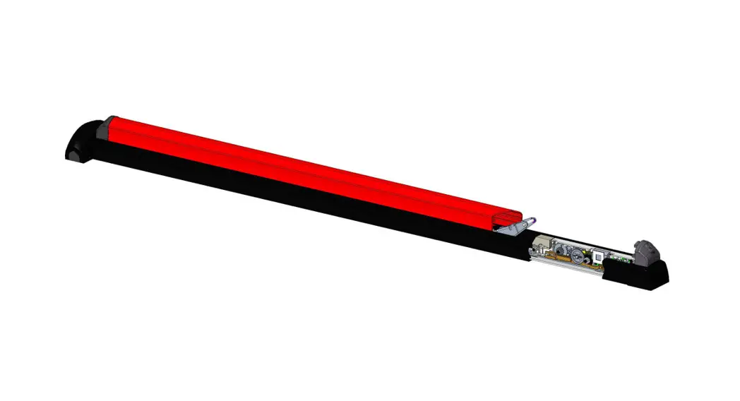
With eFAST MORTICE, the panic exit device and lock latchbolt can be withdrawn remotely.
After the lock has been opened, eFAST keeps the latchbolt and the panic exit device withdrawn for 3 seconds (factory default setting). When this time has elapsed, the panic exit device automatically shuts.
The automatic locking time can be set for up to 180 seconds by connecting to a PC using the programming cable (accessory item 1.07030.41.0).
If the CISA motor is fitted with a timer, the hold open function can be activated at pre-defined times of the day.
INSTALLATION
INTRODUCTION
This manual is an integral part of the product and has been compiled by the manufacturer to provide everyone authorised to interact with it with the information they may need.
SAFETY REGULATIONS
Read the instructions in the installation and user manual carefully.
All installation and maintenance operations which require precise technical expertise or particular skills must be carried out exclusively by qualified personnel with the relevant qualifications and experience in the sector.
![]() The CISA MOTOR is powered by a power supply with 12V
The CISA MOTOR is powered by a power supply with 12V ![]() ,l=2A output.
,l=2A output.
For more information, please refer to the section “Power supply characteristics”.
Disconnect the system from the mains during installation.![]() Do NOT perform electric welding on the lock or any parts of the lock when installed on the door.
Do NOT perform electric welding on the lock or any parts of the lock when installed on the door.![]() Situations arising from momentary power failures are given in the instruction sheet for the panic exit devices 1.59751.00.0 / 1.59751.01.0.
Situations arising from momentary power failures are given in the instruction sheet for the panic exit devices 1.59751.00.0 / 1.59751.01.0.
MOTOR CHARACTERISTICS
![]() See the eFAST MORTICE panic exit device manual
See the eFAST MORTICE panic exit device manual![]() Do not connect the product directly to the mains 230V ~.
Do not connect the product directly to the mains 230V ~.
CISA declines all responsibility for the compliance of the existing system to current regulations.
CABLE CHARACTERISTICS![]() See the eFAST MORTICE panic exit device manual
See the eFAST MORTICE panic exit device manual![]() Use the cable supplied with the lock only.
Use the cable supplied with the lock only.![]() CISA declines all responsibility for the compliance of the existing system to current regulations.
CISA declines all responsibility for the compliance of the existing system to current regulations.
POWER SUPPLY CHARACTERISTICS
The power supply is not supplied with the kit. See item 1.07060.10.0 in the accessories section.![]() Do not connect the product directly to the mains 230V ~.
Do not connect the product directly to the mains 230V ~.![]() A power supply with the following characteristics is recommended:
A power supply with the following characteristics is recommended:
- Output: 12V,
 2A
2A - Protection with fuse 2A – 250V
- Protection: OVP (overvoltage), OCP (overcurrent)
- Certifications: CE, in compliance with directives 2014/30/EU, 2014/35/EU Class 2 (double insulation), LPS source (in compliance with IEC 60950), SELV, UL Listed or UL Recognized
OPERATION
INTERFACING FOR OPENING
![]() See the eFAST MORTICE panic exit device manual
See the eFAST MORTICE panic exit device manual
Diagram 1: example of button/switch connection to lock power supply.
Diagram 2: example of lock connection to intercom![]() The electric current produced by some intercoms can be high, keeping the panic exit device open even after the opening button has been released.
The electric current produced by some intercoms can be high, keeping the panic exit device open even after the opening button has been released.
It is advisable to interface the intercom with a repeater relay and connect the motor as shown in diagram 3 if necessary.
Diagram 3: example of lock connection to an intercom using a repeater relay
INTERFACING FOR PANIC EXIT DEVICE STATUS
![]() See the eFAST MORTICE panic exit device manual
See the eFAST MORTICE panic exit device manual![]() Connect devices with a maximum current absorption of 0.5A and a maximum voltage of 60V. CISA declines all responsibility for the compliance of third-party devices used
Connect devices with a maximum current absorption of 0.5A and a maximum voltage of 60V. CISA declines all responsibility for the compliance of third-party devices used
It is possible to connect the 12V![]() lights (see the accessories) directly to the lock power supply. Respect the polarity (+/-) of the lights/LEDs.
lights (see the accessories) directly to the lock power supply. Respect the polarity (+/-) of the lights/LEDs.
A repeater relay (item 1.07022.20.0) is needed to control locks, electric strike coils or 230V devices.
DIAGNOSTICS
When installation is complete, check operation and any sound signals.
Sound signal are emitted to indicate errors and malfunctions.
| Status | Action | Sound/visual signals (*) |
| On | System correctly started up | 2 short sound signals – Flashing green LED inside the motor |
| Mechanical actions | Engaging/withdrawing deadbolts | No sound signal |
| Motor actions | Complete opening (latchbolt + deadbolts) | 2 short sound signals |
| Motor actions | Reverting to starting position | No sound signal |
| Motor actions | Motor movement | Flashing yellow LED inside the motor |
| Motor actions | Setting hold open mode | Yellow LED on inside the motor |
| Error | Rod sensor blocked | 1 long sound signal – Red LED on inside the motor |
| Error | Motor in safety timeout | 2 long sound signals – Red LED on inside the motor |
| Error | Motor blocked mechanically | 3 long sound signals – Red LED on inside the motor |
| Error | Incorrect power supply voltage Vin <11V r. or Vin >16V r_ | 4 long sound signals – Red LED on inside the motor |
(*) = Sound signals can be disabled through the PC.
FAQ
| FAQ | Action | Sound signals | Flashing signals (LEDs Inside the motor) | Possible solution |
| #1 | On When I turn the motor on, it emits a sound signal that lasts 3 seconds. Possible cause: Damaged firmware | 1 error signal (3 sec ON) | Red LED on | Call technical assistance to upgrade FW or replace the motor |
| #2 | on When I turn the motor on, it emits 3 long sound signals Possible cause: Has not reverted to the correct starting position | 3 long sound signals (0.5s ON- 0.5s OFF) | Red LED on | Call technical assistance or replace the motor |
| #3 | Error rod sensors During motor movement, it emits one long sound signal Possible cause: Latchbolt/deadbolts not withdrawn properly | 1 error signal (0.5s ON- 0.5s OFF) | Red LED on | Check rod is sliding properly. Loosen motor screws. |
| #4 | Motor timeout error After 5 seconds from opening signal, it emits two long sound signals Possible cause: The motor is not in the correct position | 2 error signals (0.5s ON- 0.5s OFF) | Red LED on | Call technical assistance or replace the motor |
| #5 | Lock remains open In hold open mode The lock does not close after giving the opening command Possible cause: Opening impulse still active | – | Yellow LED on | The lock remains open because it is still receiving an opening command. Connect the wires as shown in diagram 1. Check the system. |
| #6 | Sound signals not audible Possible cause: Volume set to OFF | Check settings on PC |
PROGRAMMING
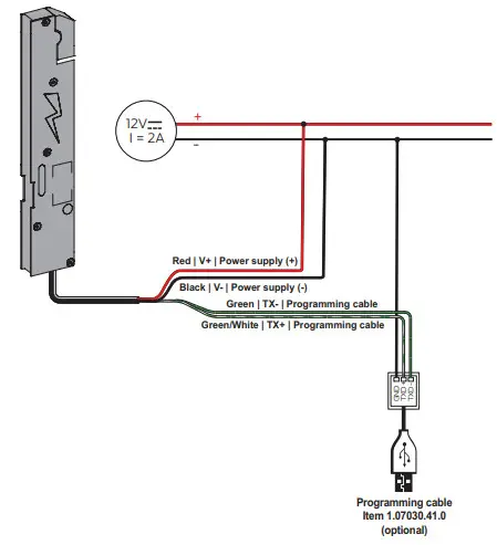
A programming cable (accessory 1.07030.41.0) can be used to set the opening time and the volume of the sound signals, control the number of openings and upgrade the lock software.![]() Only authorised CISA technical staff and locksmiths should programme the motor and use the programming software.
Only authorised CISA technical staff and locksmiths should programme the motor and use the programming software.
Procedure:
- Request access to the “CisaMotorApp” programme on the CISA website (https://www.cisa.com/CISAmotor);
- Connect the cables as shown in the diagram below;
- Power up the lock;
- Start up the “CisaMotorApp” programme on a PC;
- Open the COM port;
- Select the opening time or the desired volume and click on “Save”
N.B.: Visit the CISA website for more details.
https://www.cisa.com/CISAmotor
ACCESSORIES
CISA S.p.A. reserves the right to make any change to the products illustrated in this catalogue without prior notice.
 | Concealed cable guard | 1 06515 00 0 |
 | Internal cable guard with spring | 1 06515 15 0 |
 | External cable guard with spring (L=300 mm). | 1 06515 20 0 |
| External cable guard with spring (L=600 mm). | 1 06515 21 0 | |
 | Red LED | 1 07126 01 0 |
| Green LED | 1 07126 02 0 | |
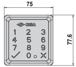 | Cabled keypad for individual access control by PIN code, for E0000 CISA MOTOR series Polished black finish AVAILABLE FINISHES – Satin-finished chrome (fin. B1) | 1 06525 77 0 |
 | Power supply cable (L = 4 m). | 1 07030 40 0 |
 | Programming cable | 1 07030 41 0 |
 | Power supply: – Input: 110÷240V ~ 50/60Hz 0.7A – Output: 12V – Certified UL Listed | 1 07060 10 0 |
About Allegion
Allegion (NYSE: ALLE) is a global pioneer in seamless access, with leading brands like CISA®, Interflex®, LCN®, Schlage®, SimonsVoss®andVon Duprin®. Focusing on security around the door and adjacent areas, Allegion secures people and assets with a range of solutions for homes, businesses, schools and institutions. Allegion had $2.7 billion in revenue in 2020, and its security products are sold around the world.
For more, visit allegion.com.
![]()
![]()
![]() CISA SpA
CISA SpA
Via Oberdan 42
48018 Faenza (RA) Italy![]() Ph. +39 0546 677111
Ph. +39 0546 677111
Fax +39 0546 677150![]() Customer Service and Technical Support
Customer Service and Technical Support
+39 0546 188 0070
cisa.com
[email protected]![]()
![]()
Code 089207720A
www.cisa.com
© 2022 Allegion


