![]()
Clavex Pro
Enhanced
Autoclave Sterilization Controller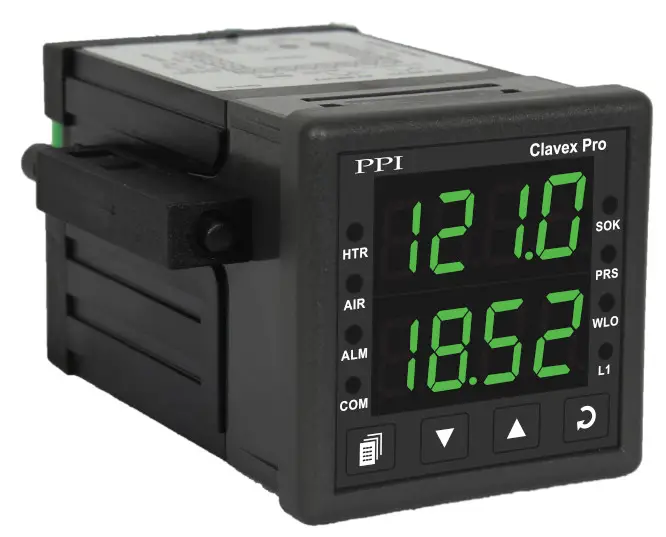
User Manual
Section 1 FRONT PANEL LAYOUT
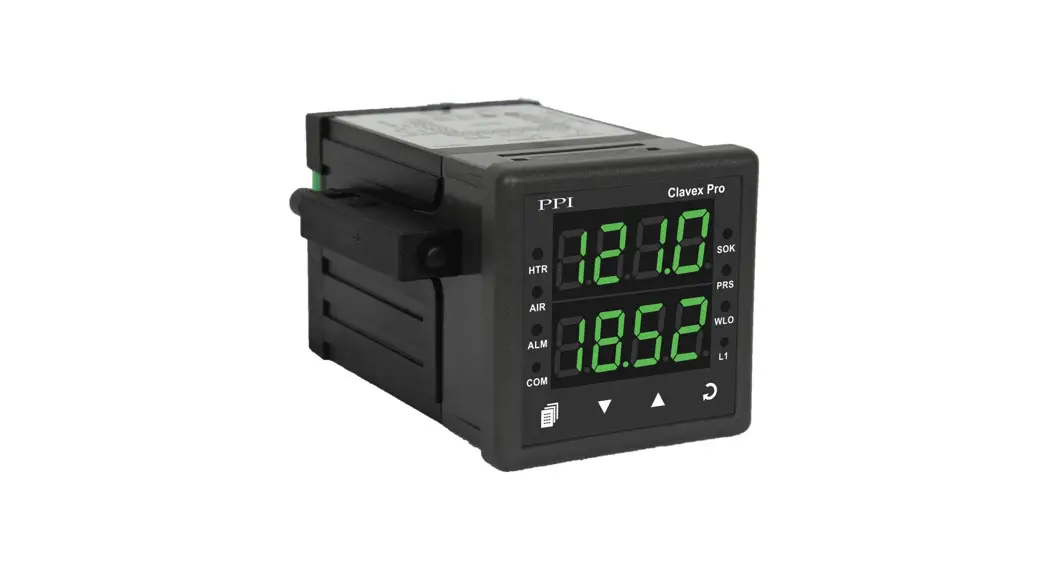
The controller front panel comprises of digital readouts, LED indicators and tactile keys as shown in Figure 1.1 below. 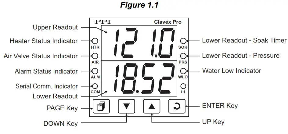
READOUTS
The Upper Readout is a 4 digit, 7-segment bright green LED display and usually displays the Temperature Value in °C. In Program Mode, the Upper Readout displays parameter values/options. The Lower Readout is a 4 digit, 7-segment bright green LED display and usually displays either Control Setpoint value or
Saturated Steam Pressure value or the balance Soak Time value, depending on the autoclave cycle state. In Program Mode, the Lower Readout displays parameter names (prompts).
INDICATORS
There are 8 front panel red LED indicators. These indicator show various statuses. The Table 1.1 below lists each LED indicator (identified by the front panel legend) and the associated status it indicates.
Table 1.1
| Indicator | Function |
| HTR | Heater ON/OFF Status. |
| AIR | Air Outlet Valve Open / Close status. |
| ALM | Alarm Status. Flashes while Alarm is Active. |
| COM | Serial Communication Status. Flashes when data is being exchanged with Master Device. |
| SOK | Glows / Flashes while the lower readout is indicating elapsed soak time. |
| PRS | Glows when the lower readout is indicating autoclave pressure value. |
| WLO | Water Level Status. Flashes if water level is LOW. |
| L1 | Unused. |
KEYS
The Table 1.2 lists the four front panel keys and the associated function.
Table 1.2
Symbol | Key | Function |
| PAGE | Press to enter or exit set-up mode. |
| DOWN | Press to decrease the parameter value. Pressing once decreases the value by one count; keeping pressed speeds up the change. |
| UP | Press to increase the parameter value. Pressing once increases the value by one count; holding pressed speeds up the change. |
| ENTER | Press to store the set parameter value and to scroll to the next parameter on the PAGE. |
Section 2 BASIC OPERATIONS
POWER-UP
Upon power-up all displays and indicators are lit on for approximately 3 seconds. This is followed by the indication of the controller model name (CLAv) on the Upper Readout and the firmware version (01.05) on the Lower Readout, for approximately 1 second.
MAIN DISPLAY MODE
After the Power-up display sequence, the Upper Readout starts showing the Temperature Value in °C and the Lower Readout indication depends on the autoclave cycle state (described below). This is the MAIN Display Mode that shall be used most often.Autoclave Cycle Operation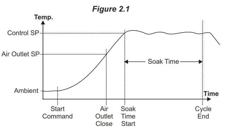 Step 0 (Idle State – Start Command Awaited)
The Lower Readout shows the message (Start). The front panel indicators SOK and PRS are off. The heater is kept OFF and the air outlet is kept ON. Use either front panel ‘ENTER’ Key or back panel Remote Key to issue ‘Start’ command to initiate a new autoclave cycle.
Step 1 (Temperature Raised to Air Outlet SP)
The Lower Readout shows the Control Setpoint value. The front panel indicators SOK and PRS are both on, indicating that the SP value is being shown on the Lower Readout. Both the heater and air outlet are maintained ON. As soon as the temperature reaches the Air Outlet SP, the air outlet is turned OFF.
Step 2 (Temperature Raised to Control SP)
The Lower Readout shows the Saturated Steam Pressure value in either Kg/cm² or PSI after the temperature crosses 100.0 C. The front panel indicator SOK is off while PRS is on, indicating that the Pressure value is being shown on the Lower ° Readout. The heater is kept ON until the temperature reaches the Control SP. As soon as the temperature reaches the Control
SP, the soak timer starts counting down. (For the detailed Soak Timer operation, refer Section 5 : Soak Timer Parameters.)
Step 3 (Temperature Maintained at Control SP)
The Lower Readout shows the balance Soak Time in Minutes:Seconds format. The front panel indicator PRS is off. The indicator SOK flashes if the timer is counting down and glows steadily if the timer is in hold state. The heater is appropriately switched ON and OFF to maintain the temperature at Control SP while the Soak Timer is counting down to 0. During this time the Saturated Steam Pressure value can be viewed by holding the UP or DOWN key pressed. Upon completion of Soak Time, the cycle ends and the controller re-enters Step 0 (Idle State).
Notes
- The running cycle is aborted if Low water level is detected. Also, a new start command is not accepted until the water level error is removed. While the level is low, the Lower Readout flashes the message (Low Level).
- After start of the Soak timer; if for any reason, the temperature falls below the Air Outlet SP or rises above the Control SP by more than the ‘Fail-safe Deviation’, the Autoclave cycle is aborted.
PV Error Indications
The PV Error type is flashed on the Upper Readout. Refer Table 2.1.
Message | Error Type | Cause |
| Over-range | PV above Max. Range |
| Under-range | PV below Min. Range |
| Sensor Open | Sensor Open / broken |
ALARM FUNCTIONS
The Output – 3 Relay/SSR is provided as an Alarm Output that activates under the following conditions.
- End of Soak Timer
The Alarm activates as soon as the soak timer reaches 0.This alarm indicates the end of the currently running autoclave cycle. - Process High
The Alarm activates if the temperature deviates above the control setpoint by more than the set band value (see ‘Operator Page and Parameters’). - PV Error
The Alarm activates if the measured temperature value crosses the specified Max. or Min. range for the selected sensor type (that is, under or over range). The Alarm also activates if the sensor input is disconnected.
Under any of the above Alarm conditions, press the front panel ‘ENTER’ key to acknowledge the Alarm (de-activated the relay).
OPERATOR PAGE AND PARAMETERS
The controller provides a separate page that contains parameters that require frequent settings by the operator. The page is called Operator Page and the parameters are called Operator Parameters. The availability of operator parameters is controlled at supervisory level and these parameters are not affected by the master lock status.
Accessing Operator Page & Adjusting Parameters
Step through the following sequence to open the operator page and to adjust the operator parameter values.
- Press and release PAGE key. The Lower Readout shows (PAGE) and Upper Readout shows (0).
- Press ENTER key. The Lower Readout shows prompt for the first available operator parameter and the Upper Readout shows value for the parameter.
- Use UP/DOWN keys to adjust the value and then press ENTER key to store the set value and scroll to the next parameter.
The controller automatically reverts to MAIN Display Mode upon scrolling through the last operator parameter. Alternatively, use PAGE key to return to MAIN Display Mode.
The PAGE 0 : Operator Parameters are described in Table 2.2 below.
Table 2.2
| Parameter Description | Settings (Default Value) |
| CONTROL SETPOINT The Setpoint value at which the autoclave temperature value is maintained for the set soak time duration. | Setpoint Low Limit to Setpoint High Limit (Default : 121.0) |
| AIR OUTLET SETPOINT The setpoint value at and above which the Air Outlet valve is kept closed to build saturated steam pressure. | Setpoint Low Limit to Setpoint High Limit (Default : 100.0) |
| SOAK TIME The time duration in ‘Minutes’ for which the autoclave temperature is maintained at the set control setpoint value. | 1 to 999 Minutes (Default : 20) |
| HIGH ALARM DEVIATION SETPOINT The positive deviation value above the control setpoint for Process High Alarm. | 1 to 10 or 0.1 to 10.0 (Default : 5.0) |
| FAIL-SAFE DEVIATION SETPOINT The positive deviation value above the control setpoint for automatic abortion of the cycle for safety. Upon abortion, the heater is switched off and the air outlet valve is opened to release the pressure. | 3 to 20 or 0.3 to 20.0 (Default : 10.0) |
| CYCLE ABORT COMMAND Set to ‘Yes’ (to be followed by proper pass code entry) to abort a running autoclave cycle. | Yes |
| CYCLE ABORT PASS CODE After setting the Cycle Abort Command to ‘Yes’, set this pass code to an appropriate value for actual cycle abortion. | 0 to 250 (Default : 0) |
Section 3 SET-UP MODE : ACCESS AND OPERATION
The various parameters are arranged in different groups, called PAGES, depending upon the functions they represent. Each group is assigned a unique numeric value, called PAGE NUMBER, for its access.
The parameters are always presented in a fixed format: The Lower Readout displays the parameter prompt (Identification Name) and the Upper Readout displays the set value. The parameters appear in the same sequence as listed in their respective sections.
SET-UP MODE
The Set-up Mode allows the user to view and modify the parameter values. Follow the steps below for setting the parameter values:
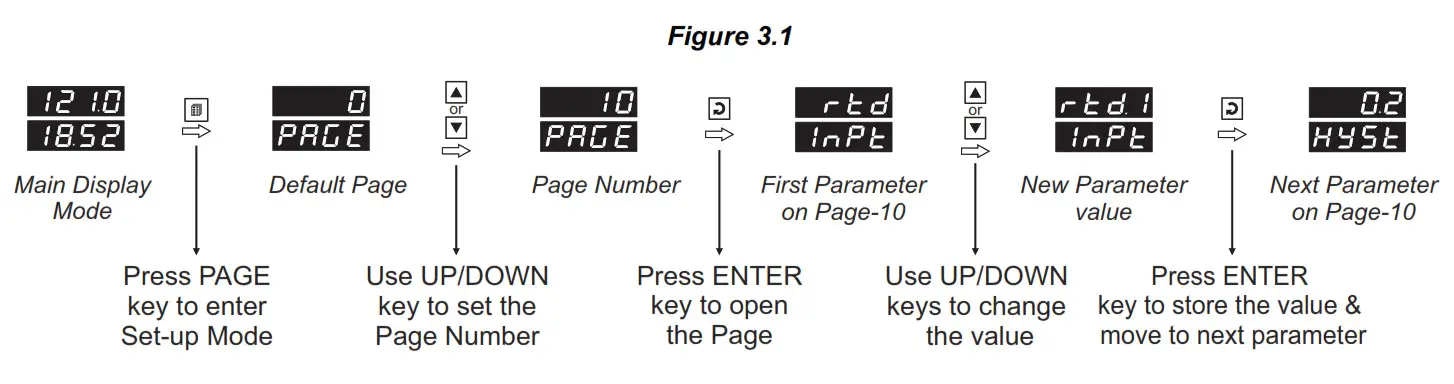
- Press and release PAGE key. The Lower Readout shows PAGE and the Upper Readout shows page number 0. Refer Figure 3.1.
- Use UP / DOWN keys to set the desired PAGE NUMBER.
- Press and release ENTER key. The Lower Readout shows the prompt for the first parameter listed in the set PAGE and the Upper Readout shows its current value. If the entered PAGE NUMBER is invalid (contains no parameter list or any associated function), the controller reverts to the MAIN Display Mode.
- Press and release the ENTER key until the prompt for the required parameter appears on the Lower Readout. (The last parameter in the list rolls back to the first parameter).
- Use UP / DOWN keys to adjust the parameter value. (The display flashes if UP key is pressed after reaching the
maximum value or DOWN key is pressed after reaching the minimum value). - Press and release the ENTER key. The new value gets stored in the controller’s non-volatile memory and the next parameter in the list is displayed.
The Figure 3.1 illustrates the example of altering the value for the parameter ‘Input Type’.
Notes
- To exit the set-up mode and return to the MAIN Display Mode, press and release PAGE key.
- If no key is pressed for approximately 30 seconds, the set-up mode times out and reverts to the MAIN Display Mode.
MASTER LOCKING
The controller facilitates locking all the PAGES (except Operator PAGE) by applying Master Lock Code. Under Locking, the parameters are available for view only and cannot be adjusted. The Master Lock, however does not lock the operator parameters . This feature allows protecting the rather less frequently used parameters against any inadvertent changes while making the frequently used operator parameters still available for any editing. For enabling / disabling the Lock, step through the following sequence:
Locking
- Press and release PAGE key while the controller is in the MAIN Display Mode. The Lower Readout shows PAGE and the Upper Readout shows 0.
- Use UP / DOWN keys to set the Page Number to 123 on the Upper Readout.
- Press and release ENTER key. The controller returns to the MAIN Display Mode with the Lock enabled.
The Figure 3.2 below illustrates the Locking procedure.
![]()
UnLocking
Repeat the Locking procedure twice for unlocking.
Section 4 PAGE 10 : INPUT / OUTPUT CONFIGURATION PARAMETERS
Table 4.1
| Parameter Description | Settings (Default Value) |
| INPUT TYPE Select Input Type depending upon the resolution required. | |
| HYSTERESIS Sets a differential (dead) band between the ON and OFF heater states. Keep it large enough to avoid frequent switching of the heater without losing the desired control accuracy. | 1 to 999°C or 0.1 to 999.9°C (Default : 2.0) |
| SETPOINT LOW LIMIT Use this limit to prevent accidental under settings of the ‘Control’ and ‘Air Outlet’ setpoints. | Min. Range for the selected Input Type to Setpoint High (Default : 90.0 °C) |
| SETPOINT HIGH LIMIT Use this limit to prevent accidental over settings of the ‘Control’ and ‘Air Outlet’ setpoints. | Setpoint Low to Max. Range for the selected Input Type (Default : 150.0 °C) |
| UNITS FOR PRESSURE Select the units for saturated steam pressure from Kg/cm² and PSI. | (Default : Kg/cm²) |
Section 5 PAGE 15 : SOAK TIMER PARAMETERS
(Refer end of this section for detailed Soak Timer Operation)
Table 5.1
| Parameter Description | Settings (Default Value) |
| SOAK TIME The time duration in ‘Minutes’ for which the autoclave temperature is maintained at the set control setpoint value. | 1 to 999 Minutes (Default : 20) |
| TIMER-START BAND The temperature band around the control setpoint. The soak timer starts counting down once the Temperature enters this band. | 1 to 5 or 0.1 to 5.0 (Default : 1.0) |
| HOLDBACK STRATEGY None Temperature based timer pause is not required. Up Timer is paused if Temperature is outside holdband and above Control SP . Down Timer is paused if Temperature is outside holdband below Control SP. Both Timer is paused if Temperature is outside holdband both above and below Control SP. |
|
| HOLD BAND Sets the temperature limit(s) with respect to the SP for the soak timer to pause. This ensures guaranteed soak time elapse. | 1 to 5 or 0.1 to 5.0 (Default : 1.0) |
| END-OF-SOAK ALARM TIME The Output-3 Relay/SSR activates at the end of soak timer to indicate an end of the running autoclave cycle. This parameter value sets the time interval for which the Alarm output remains activated before turning off. (The user can also use Acknowledgment key to turn off the output.) |
5 to 250 Sec. (Default : 10 Sec.) |
| POWER-FAIL RECOVERY METHOD Abort The timer operation is suspended until a new start command is issued. Start The timer re-runs the complete soak time. |
|
SOAK TIMER OPERATION
Figure 5.1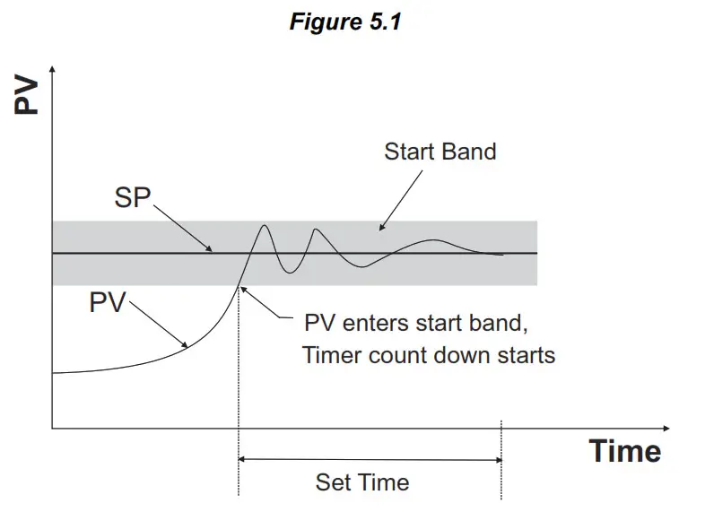
Basic Operation
The Soak Timer is essentially a Setpoint Dependent Timer. That is, after issuance of Start Command, the count down starts only after the Temperature Value reaches within timer ‘Start Band’. The timer start band is a symmetrical band centered around the Control Setpoint. For example, for a start band of 1.0°C and Control Setpoint value of 121.0°C, the count down begins once the Temperature Value reaches within 120.0°C (Control Setpoint – Start Band) to122.0°C (Control Setpoint + Start Band). Note that, once the Temperature Value enters ‘Start Band’, the timer continues to run regardless of whether the Temperature Value remains within or outside the ‘Start Band’.
Hold Band Operation
The timer is also provided with a ‘Hold Band’ that can be enabled to make sure that the timer counts down only while the Temperature Value is within the ‘Hold Band’. That is, the timer pauses (stops counting down) whenever the Temperature Value is outside the ‘Hold Band’. The ‘Hold Band’ is set with respect to the Control Setpoint and can be set above or below or above and below the Control Setpoint. For example, a 1.0°C Hold Band below the Control Setpoint (say,121.0°C) will force the timer in pause state whenever the Temperature Value is equal to or less than 120.0°C (Control Setpoint – Hold Band).
Power-fail Recovery Modes
The timer facilitates 3 different power-fail recovery modes, viz., Continue, Re-start and Abort. In Continue mode, the timer resumes to execute the balance soak time once the Temperature Value is detected within Hold Band. In Re-start mode, the timer executes the complete set time all over again. In Abort mode, the timer stops execution until a start command is issued.
Section 6 PAGE-11 : SUPERVISORY PARAMETERS
Table 6.1
| Parameter Description | Settings (Default Value) |
| OFFSET FOR TEMPERATURE VALUE This parameter adds positive or negative offset to the Measured Temperature Value for removal of thermal gradient or known sensor error. | -1999 to 9999 or -199.9 to 999.9 (Default : 0.0) |
| DIGITAL FILTER FOR TEMPERATURE VALUE This value determines the averaging rate of change of Measured Temperature Value and thus helps removing undesired rapid changes in the measured Temperature Value. The higher the filter value the better the averaging but the slower the response to actual changes. | 0.5 to 25.0 Seconds in steps of 0.5 Seconds (Default : 1.0) |
| OPERATOR PARAMETER LOCKING Setting this parameter to ‘Yes’ enables the supervisor to disallow the operator to edit the Control Setpoint, Air Outlet Setpoint and the Soak Time duration on the Operator Page. | |
| PASS CODE FOR CYCLE ABORT Set the pass code that the operator must enter if he needs to abort a running autoclave cycle by setting the Abort command to ‘Yes’ on the operator page. | 1 to 250 (Default : 22) |
| SLAVE ID This parameter assigns a unique identification number that the Master Device can use to address the instrument for data transactions. | 1 to 127 (Default : 1) |
| BAUD RATE Communication speed in ‘Bits per Second’. Set the value to match with the host baud rate. | |
| PARITY Parity setting for serial communication protocol |
| Parameter Description | Settings (Default Value) |
| COMMUNICATION WRITE ENABLE No The Read/Write parameters can only be accessed for reading. That is, the parameter values cannot be altered through serial communication. Yes The Read/Write parameters can be accessed for both reading and writing. | |
| WATER LEVEL SWITCH LOGIC Open The Water Level is considered LOW if the switch contacts are open. Close The Water Level is considered LOW if the switch contacts are close. | |
| PRESSURE VIEW Set this parameter to ‘Enable’ if it is desired to indicate the Saturated Steam Pressure (computed based on Autoclave Temperature) on the lower readout. If ‘Disable’ the Saturated Steam Pressure indication is suppressed. |
Section 7 PAGE 50 : ADDITIONAL CONTROL PARAMETER
Table 7.1
| Parameter Description | Settings (Default Value) |
| SETPOINT OFFSET This parameter value is algebraically added to the control setpoint in order to provide positive offset for switching the heater. Switching off the heater above the setpoint helps reduce the undershoot that might result in pausing the soak timer. | 0.0 to 10.0 (Default : 0.0) |
Section 8 MECHANICAL INSTALLATION
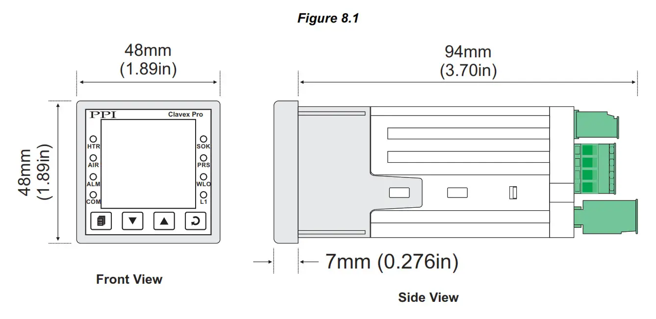
OUTER DIMENSIONS AND PANEL CUTOUT
The Figure 8.1 shows the controller outer dimensions.
PANEL CUTOUT
The Figure 8.2 shows the panel cutout requirements for a single controller. 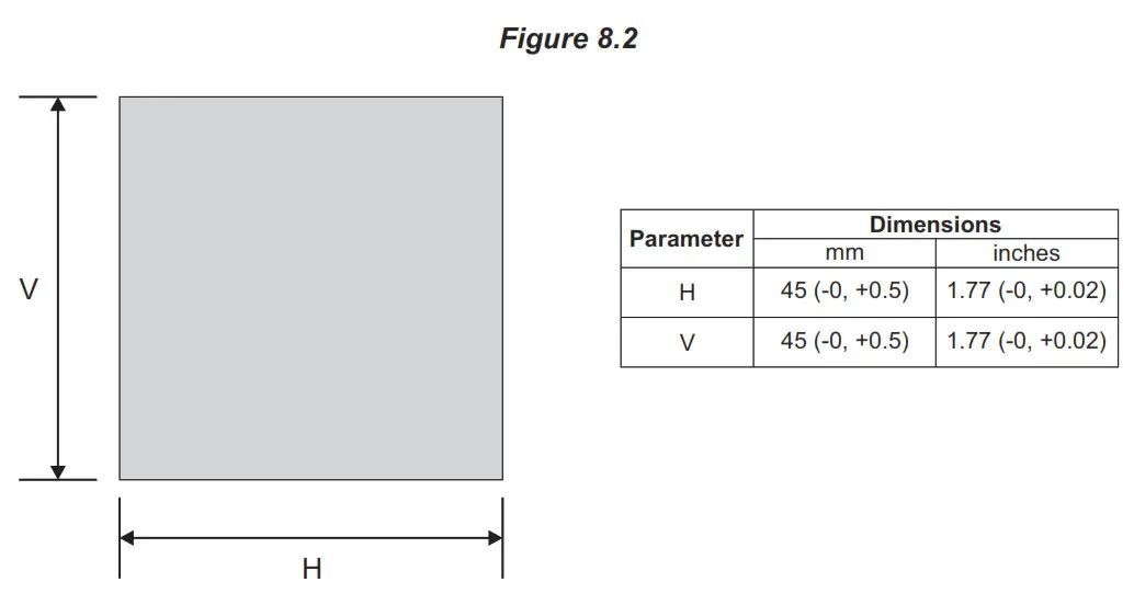
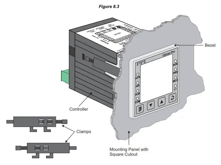
PANEL MOUNTING
Follow the steps below for mounting the controller on panel:
- Prepare a square cutout to the size shown in Figure 8.2.
- Remove the Panel Mounting Clamp from the controller Enclosure and insert the rear of the controller housing through the panel cutout from the front of the mounting panel. 3. Hold the controller gently against the mounting panel such that it positions squarely against the panel wall, see Figure 8.
- Apply pressure only on the bezel and not on the front label.
- Insert the mounting clamps on either side of the controller in the slots provided for the purpose. Rotate the screws clockwise so that they move forward until they push firmly against the rear face of the mounting panel for secured mounting.
Section 9 ELECTRICAL CONNECTIONS
![]() WARNING MISHANDLING / NEGLIGENCE CAN RESULT IN PERSONAL DEATH OR SERIOUS INJURY.
WARNING MISHANDLING / NEGLIGENCE CAN RESULT IN PERSONAL DEATH OR SERIOUS INJURY.
- The user must rigidly observe the Local Electrical Regulations.
- Do not make any connections to the unused terminals for making a tie-point for other wires (or for any other reasons) as they may have some internal connections. Failing to observe this may result in permanent damage to the controller.
- Run power supply cables separated from the low-level signal cables (like RTD, DC Linear (Voltage) signals, etc.). If the cables are run through conduits, use separate conduits for power supply cable and low-level signal cables.
- Use appropriate fuses and switches, wherever necessary, for driving the high voltage loads to protect the controller from any possible damage due to high voltage surges of extended duration or short-circuits on loads.
- Take care not to over-tighten the terminal screws while making connections.
- Make sure that the controller supply is switched-off while making/removing any connections or removing the controller from its enclosure.
CONNECTION DIAGRAM
The Electrical Connection Diagram is shown on the top side of the enclosure. The diagram shows the terminals viewed from the REAR SIDE with the controller label upright. The connecters provided for wiring are pluggable male-female type. The female parts are soldered on the controller PCBs while the male parts are with screws and removable. The rear panel electrical wiring connection diagram is shown in Figure 9.1.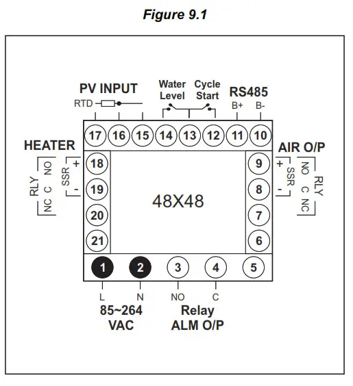
DESCRIPTIONS
PV INPUT : RTD Pt100, 3-Wire (Terminals 17, 16, 15)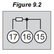 Connect single leaded end of RTD bulb to terminal 17 and the double leaded ends to terminal 16 and 15 (interchangeable) as shown in Figure 9.2 (a). Use copper conductor leads of very low resistance ensuring that all 3 leads are of the same gauge and length. Avoid joints in the cable.
Water Level : Low Water-Level Detection Digital Input (Terminals : 14, 13)
Potential-free contact closure input terminals are provided as digital inputs for low water level detection. An user programmable ‘Open’ or ‘Close’ switch position is detected as water level low.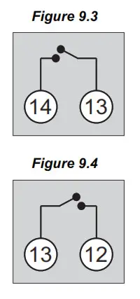 Cycle Start : Remote Cycle Start Digital Input (Terminals : 13, 12)
Potential-free contact closure input terminals are provided as digital inputs for issuance of remote Cycle Start command. An Open – to – Close transition is taken as Cycle Start Command. If the cycle is in progress, the switch position is ignored.
HEATER : Relay / SSR Drive for Heater Control (Terminals 18, 19 & 20)
AIR O/P : Relay / SSR Drive for Air Valve (Terminals 7, 8 & 9)
Relay Output
Potential-free Relay changeover contacts NO (Normally Open) and C (Common) rated 10A/240 VAC (resistive load). Refer Figure 9.5(a).
SSR Output
Connect (+) and (-) terminals of SSR to terminals 18 /9 & 19 / 8, respectively. Use Zero-Crossover, 3 to 30 VDC operated SSR. Refer Figure 9.5(b).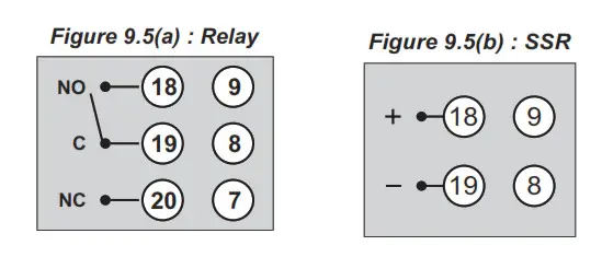
Relay ALM O/P : Potential-free Relay Contacts for Alarm Output (Terminals 3, 4)
Potential-free Relay changeover contacts N/O (Normally Open) and C (Common) rated 2A/240 VAC (resistive load) are provided as Relay output. Use external auxiliary device like contactor with appropriate contact rating for driving the actual load.![]()
RS485 : Serial Communication Port (Terminals 10, 11)
Connect terminal 11 and 10 of the controller to (+) and (-) RS485 terminals of the Master device.
To ensure reliable operation of the Serial Communication Link (without data corruption due to line noise or reflections), use a pair of twisted wires inside screened cable with the terminating resistor (100 to 150 Ohms) at one end, as shown in Figure 9.7below.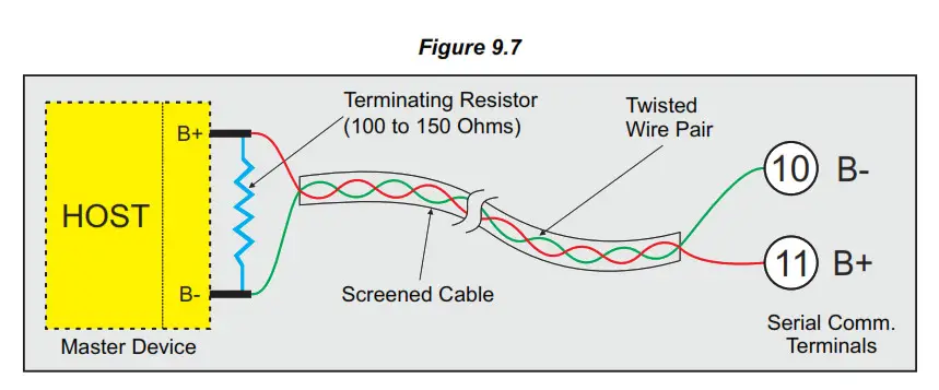 85~264 VAC : Power Supply (Terminals 1, 2)
The controller is supplied with power connections suited for 85 to 264 VAC line supply. Use well-insulated copper conductor 2 wire of the size not smaller than 0.5mm for power supply connections. Connect Line (Phase) supply line to terminal 1 and the Neutral (Return) supply line to terminal 2 as shown in Figure 9.8 below. The controller is not provided with fuse and power switch. If necessary, mount them separately. Use a time lag fuse rated 1A @ 240 VAC.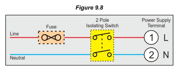
Process Precision Instruments
101, Diamond Industrial Estate, Navghar, Vasai Road (E),
Dist. Palghar – 401 210.Maharashtra, India Sales : 8208199048 / 8208141446
![]() Support : 07498799226 / 08767395333
Support : 07498799226 / 08767395333
[email protected]
[email protected],
www.ppiindia.net


